eherms valve diagram request for comment

Homebrew Talk - Beer, Wine, Mead, & Cider Brewing Discussion Forum

Help Support Homebrew Talk - Beer, Wine, Mead, & Cider Brewing Discussion Forum:

This site may earn a commission from merchant affiliate links, including eBay, Amazon, and others.

swanwick

Well-Known Member
Joined
Mar 12, 2010
Messages
181
Reaction score
12
Location
DC
I am pivoting from a Propane brew tree set-up to a 3 vessel eherms set-up. Have tanks and uniflex coming in the next few weeks. Have been trying to read up on automation and eherms configurations. I would like to start with manual valves, but configured in such a way that I can just switch to automated valves and system design is the same. My tanks are 1.5"TC and reasonably priced automated valves are 1/2"NPT so will probably buy 1/2"NPT manual valves and get 1.5"TC-->1/2"FNPT converters

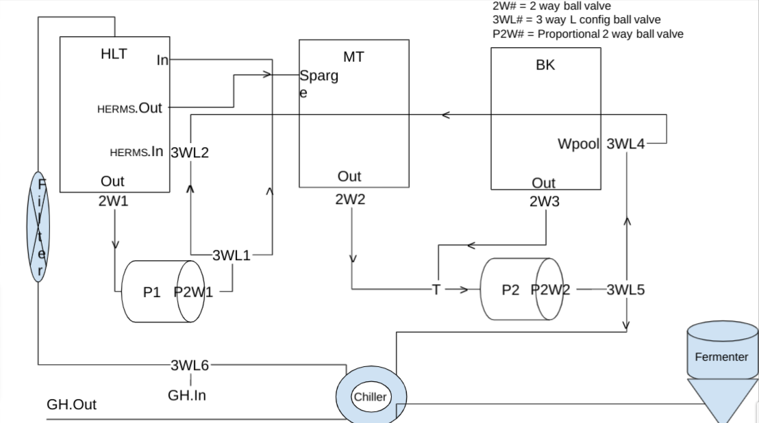
Attached is a picture of the design. I might start out with the proportional valves for fly sparging so I have left them in. The 3W valves next to them would go under the table with the pumps. Every other valve would get attached to a vessel. I have configured everything to use L config 3W valves because that seems to be the only ones that @BrunDog sells. I would probably manually connect/disconnect the garden hose (rather than 3WL6 since those steps are reasonably far apart.

Would really appreciate advice from those who have HERMS systems and especially those who have automated. Not putting a valve on the MT output seems odd/dangerous, but just a short hose to the 3way and no hoses would be moved during brewing. I had a 2W on each vessel and a simple "T" before the pump, but the config in this picture has less valves. Also, 3WL1 is to allow for HLT re-circ in addition to Sparge/MLT fill path. Do folks find that helpful to maintain temp consistency? Would be a simpler config to eliminate that if not needed. Could attach Garden Hose to that TC connection if opened up.

1641753599544.png
 
Last edited:
I thought it might be helpful to describe the uses for each 3W valve to help understand the diagram
  • 3WL1 a) HLT re-circ b) HLT to MT (mash-in, sparge)
  • 3WL2 a) mash-in b) mash re-circ
  • 3WL3 a) MLT to P2 (re-circ, sparge) b) BK to P2 (chiller)
  • 3WL4 a) whirlpool b) bypass during mash re-circ
  • 3WL5 a) whirlpool, mash re-circ b) chiller to ferment
  • 3WL6 a) strike water b) chiller cooling
This could be done with a larger number of 2W valves and T's. Is that recommended? Thx.
 
I am thinking that I should probably just stick with a two way valve on the outlet of each vessel, which would then leave me with a T (no valve) before Pump 2. Anyone know if that works? Is there cavitation at the T point that stops the pump from getting the right flow?
1642039049811.png
 
Recirculating the HLT will give you faster response time and better heat transfer to the HERMS coil. I would consider this a must for a HERMS system.

If you eventually want to automate the dough in process then you would want to add a path from the HLT to the MT output for underletting.
 
The diagram is a little confusing. Where you have lines crossing that are not connected, you may want to show a gap so it is clear they are separate.
 
Recirculating the HLT will give you faster response time and better heat transfer to the HERMS coil. I would consider this a must for a HERMS system.
Thanks. Helpful to know. I will leave that part in. It seems that people are entering low and exiting high with their HERMS. With HLT re-circ I am guessing works same either way
If you eventually want to automate the dough in process then you would want to add a path from the HLT to the MT output for underletting.
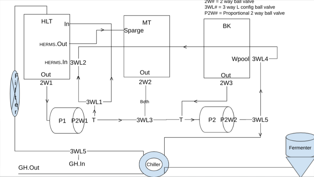
"underletting" is a whole new concept for me. Makes a lot of sense. Pouring and stirring is a very tough one man job with large batch size. The attached is a modified version. Should work, right?
1642097779820.png
[/QUOTE]
 
The diagram is a little confusing. Where you have lines crossing that are not connected, you may want to show a gap so it is clear they are separate.

Apologies. I am using Google draw and I don't think it has the capability to show crossing. Basically, every intersection is two different non-connecting hoses....so everything goes straight through the intersection. If there is an actual intersection where liquid might turn, that is indicated by a 3W valve.
 
If you eventually want to automate the dough in process then you would want to add a path from the HLT to the MT output for underletting.

Realized that I could do it by switching a 2W for a 3W at MT output rather than adding an additional 3W. New diagram
1642098866033.png

This will push some water into the hose between pump and MT out when it is needed in the direction of 3WL1, but don't see how that would be a big problem.
 
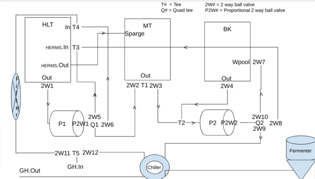
@crane has advised me to go with two way valves so I adjusted the diagram. From both pumps the outflow has three possible paths rather than two. Do folks use a T and then another T on one of the branches or just go straight to a Quad split? Seems that I now need
  • 12 2W valves
  • 2 2W proportional valves for the pump output
  • 5 Tee splitters
  • 2 Quad splitters
My vessels are TC ports, but all these valves are NPT. Do people recommend NPT Tees or TC Tees? Either way, I am going to need a lot of TC-NPT conversion fittings. Will have to count those up next.
1642341072673.png
 

Latest posts

Back
Top