eBAIB Build

Homebrew Talk - Beer, Wine, Mead, & Cider Brewing Discussion Forum

Help Support Homebrew Talk - Beer, Wine, Mead, & Cider Brewing Discussion Forum:

This site may earn a commission from merchant affiliate links, including eBay, Amazon, and others.

virgil1

Well-Known Member
Joined
May 30, 2015
Messages
152
Reaction score
27
Location
San Francisco
First off, I want to thank Kal at Electric Brewing(I bought his book..its the best) and Voltin for his thread ( https://www.homebrewtalk.com/showthread.php?t=282235 ). I based almost everything I have done on the work those two did. I wanted to 'give back' and show my build. Hope it helps someone else!
I started back in May 2015 with a Brooklyn Brewshop Everyday IPA kit my buddy got me for my birthday. While I was waiting for that to ferment, I ordered a Bayou Classic 44 QT SS pot ( http://amzn.com/B000FTLY1K ), and put a 3 piece ball valve on it from Bargain Fittings. I also ordered a bag to do BIAB. I brewed a 5-ish gallon IPA on June 22nd ( https://www.homebrewtalk.com/showthread.php?t=531230 ) . While I waited for that to ferment, I started ordering the gear to build a control box and do all electric, and I had an electrician install a 240V plug with a switch near my workbench. I have a week off ( I switched jobs) so I started my build this week. Figured I'd post each step, with the links to the parts I bought.
 
I bought a dryer cord from Amazon and a Twist Lock plug from eBay.
Parts:
Dryer Cord $11.99 http://amzn.com/B0002YE3OI
NEMA L14-30 30A 125/250V 3 Pole 4 Wire Grounding Female Cord Connector L14-30R $11.49 http://r.ebay.com/jFkryJ

Tools:
Screwdriver
Wire Stripper

Here is how the cord came:
2015-07-27 08.42.59.jpg

Here is how the plug came:
2015-07-27 08.36.55.jpg

The cord out of the bag:
2015-07-27 08.44.01.jpg

On the workbench, ready to go:
2015-07-27 09.43.21.jpg

You have to take the circle terminals off:
2015-07-27 10.00.57.jpg

All the terminals are taken off:
2015-07-27 10.03.54.jpg

Here it is all put together. You just take each wire and screw the terminal down on the plug. I didn't show too much more detail, it was pretty straight forward:
2015-07-27 10.12.15.jpg
 
I went for an ABS panel, all buttons and PID were from Auber. I used the step bit I had used to put my 3 piece ball valve into my kettle for buttons, and drilled holes in the four corners of the PID and then a jig saw to cut the PID hole. I used InkScape to make a template. It allowed me to make a big rectangle the size of the front of the panel, then circles and squares the size of the buttons (22mm) and the PID (44mm). It also allowed me to center and distribute evenly. I used painters tape to put the template on the box.

BUD Industries NBF-32018 Plastic ABS NEMA Economy Box
$21.25
http://amzn.com/B005T990I0

Buttons:
4x Illuminated Maintained Pushbutton Switch, 2 NO, 22mm. 120/240V
$11.98 each
http://www.auberins.com/index.php?main_page=product_info&cPath=7_32&products_id=223

PID:
1/16 DIN PID Temperature Controller (For SSR) (SYL-2352)
$46.50
http://www.auberins.com/index.php?main_page=product_info&cPath=1&products_id=3

Buzzer:
Flashing Buzzer, 110 or 240V AC. 22 mm
$7.86
http://www.auberins.com/index.php?main_page=product_info&cPath=7_33&products_id=215

My template taped to the box with blue painters tape.
2015-07-27 10.49.40.jpg

The buttons and the buzzer.
2015-07-27 10.55.27.jpg

The step bit I used. Marked it where 7/8" was, which is about 22mm. I didn't really end up using it. I drilled little by little and kept trying a button, then drilling more, trying, etc. Worked fine. Just went slow and took my time so the hole didn't end up too big.
2015-07-27 11.00.16.jpg

If you push the little white tab on the bottom part of the button, they come right apart.
2015-07-27 11.10.50.jpg

I drilled a hole in the middle of each one to start, then used the step bit.
2015-07-27 11.13.14.jpg

The main power button and the buzzer installed.
2015-07-27 11.15.47.jpg

The inside of the case with the power button and buzzer installed. Ignore the pieces of tape, I was trying to make sure they were in far enough so the lid closed before I drilled the holes.
2015-07-27 11.16.01.jpg

The jig saw for the PID hole. Not sure you needed this picture, but its the one I used. Worked fine.
2015-07-27 11.31.26.jpg

This is showing the four holes I drilled in the corners of the PID. I had to work them to make them a bit bigger so the jigsaw fit. Be careful. Use safety glasses.
2015-07-27 11.38.15.jpg

Everything fits!
2015-07-27 12.00.48.jpg
 
Once I got the plastic enclosure, I realized the bottom wasn't flat. I bought a sheet metal subpanel:
http://amzn.com/B005UPERKY
$14.00 each

I had to buy a couple drill bits to drill holes for the contactor(bigger hole) and the terminal strips(smaller holes). I also had to buy some M5 and M6 screws and nuts to attach the terminal strips and contactors to the sub panel.

2 Contactors:
http://amzn.com/B001KGSJ74
$9.95 each

2 Fuse Panel Mount Holders from eBay
http://r.ebay.com/8vUCTm
$2.99 each + $2.50 shipping
I went to Radio Shack and bought a pack of 1A fuses, and a pack of 10A fuses. $2.50 each pack. If your local radio shack hasn't closed, I would use them. They are more expensive on Amazon.


Terminal Strips:
one for 120V:
http://amzn.com/B005I03WOI
$5.94 each
(comes with two, really just needed one, this will fit either 6 or 8 stud size terminal connectors, but they are pretty big, so I used the smaller one for ground)

one for ground:
http://amzn.com/B008X0NNEY
$6.00 each
(comes with 5, I originally thought I could use this for the 120V, but they are really small. They will NOT fit 6 or 8 stud size terminal connectors. I just stuck 10 AWG wire under the screws with no terminal connectors, seemed to work fine.)

14 Gauge wire
http://amzn.com/B00INVEUNQ
$6.49 each
This is all black. I really liked this wire. Its 25 Feet. I would buy two of these in retrospect. I ran out and had to buy 10 more feet at the local Ace hardware. The Ace hardware wire wasn't as nice. Since it was all black, I used some different color electric tape to mark the wires. I used blue tape to show the wire went to 120V, white tape to show that it went to neutral, and yellow tape to show that it went to ground. It seemed silly to buy 3 different colors of wire for both 10 AWG and 14 AWG wire. Totally a preference thing.

10 Gauge wire
http://amzn.com/B00INVF6P2
$11.33 each
I still had some of this left, but you need this. I used it to attach to and from any receptacle that had 240V. That's the inlet from the wall to the box, and from the element socket to the contactors.

Terminals. I bought mine on Amazon, but I got one entire box of the wrong size, one that I used a few of, and another I never used(thought I could have).

14 AWG #6 stud spade terminals
I would suggest getting about 50 with a number 6 stud that fit 14 AWG wire(like these: http://amzn.com/B005HQ4QTI , $6.39 is cheap for 100 of them, though you don't need that much).

14 AWG female disconnect terminals
http://amzn.com/B00030CT56 $5.99 for 10.
These are more expensive, but you need them to connect to the switch for the relay on each side of the contactor. They are connected to the 14 AWG wire. I didn't have these in my original Amazon order. I ended up getting them at the local hardware store.

10 AWG #8 stud spade terminals
I also used some 10 AWG spade connectors. I actually only used like 10. Its only $4.50 for 50 of them: http://amzn.com/B000BVZBS4

Jumpers
http://amzn.com/B000K2IL1I
$3.69 each
Buy two packs. I jumpered the bigger 8 position terminal to have the bottom 4 terminals be neutral and top 4 for 120V. For the ground, I didn't have small jumpers, so I just used small pieces of 14 AWG wire to jumper those.

I attached the two contactors and two terminal strips to the metal sub panel. I wired up the inlet for the 240V power to one of the contactors, hooked up to the ground and neutral terminals, and hooked up the red power illuminated push button.
I just used the screw connectors on each side of the relay and put bare 10 AWG wire underneath the screw terminals and tightened them down. For the switch that trips the relays, I used the female terminal disconnects with the 14 AWG wire.

Drilled holes in the sub panel. It was a lot harder than I thought. I should have used a center punch (like this one http://amzn.com/B0037UUO60 ). The drill bit was sliding all over the place, and it was hard to get the holes just right, so things just barely lined up. I only ended up drilling two holes for each of the contactors, but I don't think they are going anywhere!
2015-07-29 14.40.18.jpg

Here it is all wired up
2015-07-29 20.07.44.jpg

Here is my wiring diagram for the pieces I hooked up.
brewpanel_wiring.png
 
I made some more updates to my previous posts. Made it clearer, added more links to what I purchased, etc. The panel is up and running and working! I'll keep updating this week(with more pictures too).
 
Why didn't you put the main power switch in series with the element power switch, and just use a single contactor?

Brew on :mug:
 
Why didn't you put the main power switch in series with the element power switch, and just use a single contactor?

Brew on :mug:

Good question. I think it's to make sure you have an 'emergency shut off' button for main power. You could do it either way. Here is my 'final' wiring diagram. I take zero credit for it. This is all PJ and voltin(from this thread https://www.homebrewtalk.com/showthread.php?t=282235 ).

brewpanel_wiring_new.png
 
The bottom part of the bigger terminal(the bottom 4 screws) is for the neutral connections. I used jumpers to connect the bottom 4 together and the top four together(I used the top four for 120V connection).
2015-07-30 08.37.28.jpg
The smaller terminal is for the ground connections. I didn't have any jumpers small enough, so I just used wire to jumper them.
2015-07-30 08.52.05.jpg
I labeled the bottom of the larger terminal 'N' for newtral and the top 'H' for hot. I tried to put white electrical tape on all the Neutral wires, and blue electrical tape on all of the 120V hot electrical wires. I would have rather had different color wire, but I already had the tape, and buying just one color wire was cheaper.
2015-07-30 08.59.48.jpg
This is how I connected X2 to 24 for the power, element and pump buttons. For the power and element, this allowed me to only run one wire back to the 120V terminal. Saves wire, makes it cleaner.
2015-07-30 09.29.45.jpg
A close up of where you have to get two spade connectors into one screw on the buttons. Be careful, the bits around the screws are plastic. Don't force it, bend the spade terminal if you need to. You can see how they make the connection.
2015-07-30 09.33.04.jpg
Alarm, alarm button(below PID) and PID connected. Not sure this helps, but including it as a close up.
2015-07-30 10.11.11.jpg
Another shot of the terminals with more neutral and hot connections.
2015-07-30 10.27.50.jpg
I used the 'female disconnect terminals' to connect the fuses. Worked really well.
2015-07-30 16.00.52.jpg
I wrote '1' to indicate a 1 Amp fuse, and wrote 10 on the other one.
2015-07-30 16.00.54.jpg
 
I used hole saws to drill the holes in the bottom of the case for the 240V inlet and the 240V lock receptacle for the heating element.

I bought the inlet on eBay:
http://r.ebay.com/LWPktt
$14.99 plus free shipping

I bought the receptacle on Amazon:
http://amzn.com/B00062BJG6
$11.79

Hole saws. These made the job super easy. Kind of pricey though. $40.00 in hole saws!
2 3/8" - $12.95
http://amzn.com/B000X2ILXS

1 3/8" - $13.90
http://amzn.com/B002LF90WG

1 1/2" - $14.18
http://amzn.com/B002LFGKQA

Created the template with Inkscape. I drew the two circles for the inlet to represent the lip.
2015-07-28 09.57.52.jpg

2 3/8" hole saw for the inlet
2015-07-28 09.58.06.jpg

The inlet
2015-07-28 10.03.38.jpg

Drill and hole saw
2015-07-28 10.05.48.jpg

Drilling the hole
2015-07-28 10.05.57.jpg

Hole drilled
2015-07-28 10.07.10.jpg

Inlet in. Sill had to drill holes for the screws to secure it
2015-07-28 10.07.23.jpg

Other two hole saws I bought. The smaller one is for the pump receptacle, the bigger one for the element.
2015-07-28 10.10.10.jpg

Both holes drilled.
2015-07-28 10.14.10.jpg

Both installed(well, dry fitted. Had to screw in later).
2015-07-28 10.23.15.jpg
 
I wanted to add the bits for the kettle element. I purchased the element and the 'hotpod' from brewhardware.com.

https://www.brewhardware.com/product_p/hotpod-ewl3.htm
https://www.brewhardware.com/product_p/element5500.htm

I bought an L6-30P cord
http://amzn.com/B00F17QD6W

Knockout punch:
http://amzn.com/B002NQZ0J0

Here is the element and the hotpod I bought
2015-07-27 15.37.18.jpg

I bought the GreeLee punch.
2015-07-28 10.36.08.jpg

I went 1 3/4" up
2015-07-28 10.44.09.jpg

I used the step bit to drill a pilot hole.
2015-07-28 11.02.25.jpg

Here is the GreeLee Punch on
2015-07-28 11.13.18.jpg

Teflon tape on the threads
2015-07-28 11.17.10.jpg

Put the element in with the ring on the outside.
2015-07-28 11.22.41.jpg

Slide the rubber washer on, then the nut.
2015-07-28 11.26.52.jpg

The ground wire nut was a PIA to get on. It's a tight fit.
2015-07-31 13.03.22.jpg

In fact...all the wires were a tight fit. Works great though! I used spade terminal connectors on all of the wires.
2015-07-31 13.07.59.jpg
 
How did you mount the receptacles in the enclosure? I have a different enclosure but the same receptacles. I thought about tapping the hole but the metal is too thin.
 
How did you mount the receptacles in the enclosure? I have a different enclosure but the same receptacles. I thought about tapping the hole but the metal is too thin.
I just drilled holes with the hole saws for the big holes, and drilled small hoes for the screws to hold them down. Make sense? If not I can take more pics. Later...I am brewing right now!
 
Sure, makes sense for your plastic enclosure. The screws have some meat to create its own thread in the plastic. Not sure it will hold things so well with a thin metal enclosure wall.
 
Yep, thought about that after and realized that I'm an idiot.

Yeah, I drilled my holes in the bottom too big so I had to use nuts with them. I wanted to go all metal enclosure, but seemed so much harder to cut holes. You can get punches(even square ones!) and resell them on ebay, but I didn't want to do that. Box is working well. Kegerator next!
 
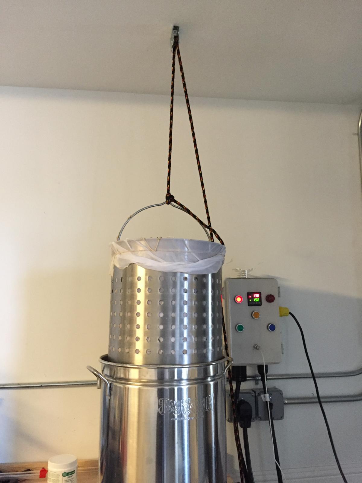
I have done a couple brews, and the system works great. Post to this thread if you have any questions. I think I posted everything. One thing I noticed is that it took a little while for the PID to 'learn' how to keep my set temp, but once it did, it was rock solid. Love it! Kegerator and fermentation chamber is next for me. A few pics for the last brew.

2015-08-22 16.22.25-1.jpg


2015-08-22 18.46.56.jpg
 
What was you final cost for the build minus you brew pot? How many hours do you think you had in putting it together? I am looking at building a system similar to yours.
 
Looks good. The temp probe is on the outlet valve? Are you recirculating to the top of the kettle?
 
Can you post a short video of those buttons. I am thinking about using them but am not sure if i want to use them or normal switches.. Also, what does the wort come back into the kettle through?
 
Can you post a short video of those buttons. I am thinking about using them but am not sure if i want to use them or normal switches.. Also, what does the wort come back into the kettle through?

Attached a video, let me know if you need more. My wiring is a bit messy, but gives you an idea of how they are wired up. I really like the buttons. You can get cheaper ones on ebay, but Auber ships quick. I can't say they make 'better buttons', as some people claim they are made in China and Auber just resells(I cannot prove or refute that).
http://www.auberins.com/
The wort comes back through the lid. See pic.

2015-08-22 17.38.35.jpg


View attachment 2015-10-17 09.58.36.mov
 
The wort comes back through the lid.

Are you using a bushing or a nipple on the weldless kit for your lid? Any fittings or hose on the inside or does the wort just splash down from the port? I'm installing a weldless port to my lid too and considering adding a barb or camlock on the inside of my lid so that I can submerge a hose on my recirculation return.
 
Attached a video, let me know if you need more. My wiring is a bit messy, but gives you an idea of how they are wired up. I really like the buttons. You can get cheaper ones on ebay, but Auber ships quick. I can't say they make 'better buttons', as some people claim they are made in China and Auber just resells(I cannot prove or refute that).
http://www.auberins.com/
The wort comes back through the lid. See pic.

That was perfect, thanks. They look like they're really 'clicky' I like em..

Whats on the other side of that lid.. do you have a sprayer or something?

Alex.
 
Are you using a bushing or a nipple on the weldless kit for your lid? Any fittings or hose on the inside or does the wort just splash down from the port? I'm installing a weldless port to my lid too and considering adding a barb or camlock on the inside of my lid so that I can submerge a hose on my recirculation return.

I used a weldless kit. All the parts were from bargain fittings. I did put a barbed fitting on the inside, and I have about a 8 inch hose attached. Works well.
 
I used a weldless kit. All the parts were from bargain fittings. I did put a barbed fitting on the inside, and I have about a 8 inch hose attached. Works well.

Perfect--thanks. I plan on doing the same.
 
What was you final cost for the build minus you brew pot? How many hours do you think you had in putting it together? I am looking at building a system similar to yours.

I added it all up again.

$400 for all panel and electrical (not counting having an electrician install 240V near my work bench. Our dryer is gas, so no 240V in garage already)
$280 for chugger pump + silicone tubing and all of the SS Camlock connectors from bargain fittings.
$240 in other misc tools and the kettle. $90 for the kettle. Then I bought hole saws, step bit, some files and and the knockout punch($90 for that)

I have most of the costs listed in the thread, but here they are all together:

Panel and electrical
----------------------
11.99 dryer cord
11.49 locking plug
21.25 BUD box
47.92 4 auber buttons
46.5 auber PID
7.86 auber buzzer
14.40 sheet metal insert for BUD
19.28 2 contactors
8.50 fuse holders
5.55 terminal strip - large
3.71 terminal strip - ground
12.98 14 G wire(50 ft)
12.99 10G wire(25 ft)
6.39 #6 spade terminals
5.99 female disconnect terminals
4.99 #8 spade terminals
7.38 jumpers (2)
14.99 240V Inlet
13.11 240V Receptacle
26.00 hotpod
37.00 element
32.99 cord for heating element
6.39 SSR heat sink
20.00 SSR
$399.65

Tools
---------
12.26 Step bit
6.09 Files
88.95 Kettle
41.03 Hole Saws
90.94 Knockout punch
$239.27

Pump
----------
28.20 Silicone Tubing 10 ft 1/2" ID, 3/4" OD
120.62 Bargain Fittings
132.89 Chugger pump
$281.71
 
Hi! In case any one is following this, and lives in the Bay Area(SF Bay Area), I want to give this to someone. I have gotten out of the hobby(have a 5 year old now, busy with other projects, etc), and would like someone to get some good use out of it. Email me at [email protected] if interested.
 
Back
Top