• Please visit and share your knowledge at our sister communities:
  • If you have not, please join our official Homebrewing Facebook Group!

    Homebrewing Facebook Group

Dual 120V Electric Brewing Controller

Homebrew Talk

Help Support Homebrew Talk:

This site may earn a commission from merchant affiliate links, including eBay, Amazon, and others.

flexmurphy

Member
Joined
May 15, 2014
Messages
10
Reaction score
3
I'm sure there's already a post addressing this, but I haven't been able to find it.

I'm designing an electric brewing controller with the following characteristics:

- Dual 120V 1500W heating elements
- Pump control
- Element 1 is straight on/off at full power
- Element 2 is able to switch from PID/SSR temperature control to manual on using a three-position on/off/on SPDT switch
- In either PID or manual mode, Element 2 also has a manual temperature control dial to adjust heat output
- LED indicator lights on all three loads (Element 1, Element 2, Pump)

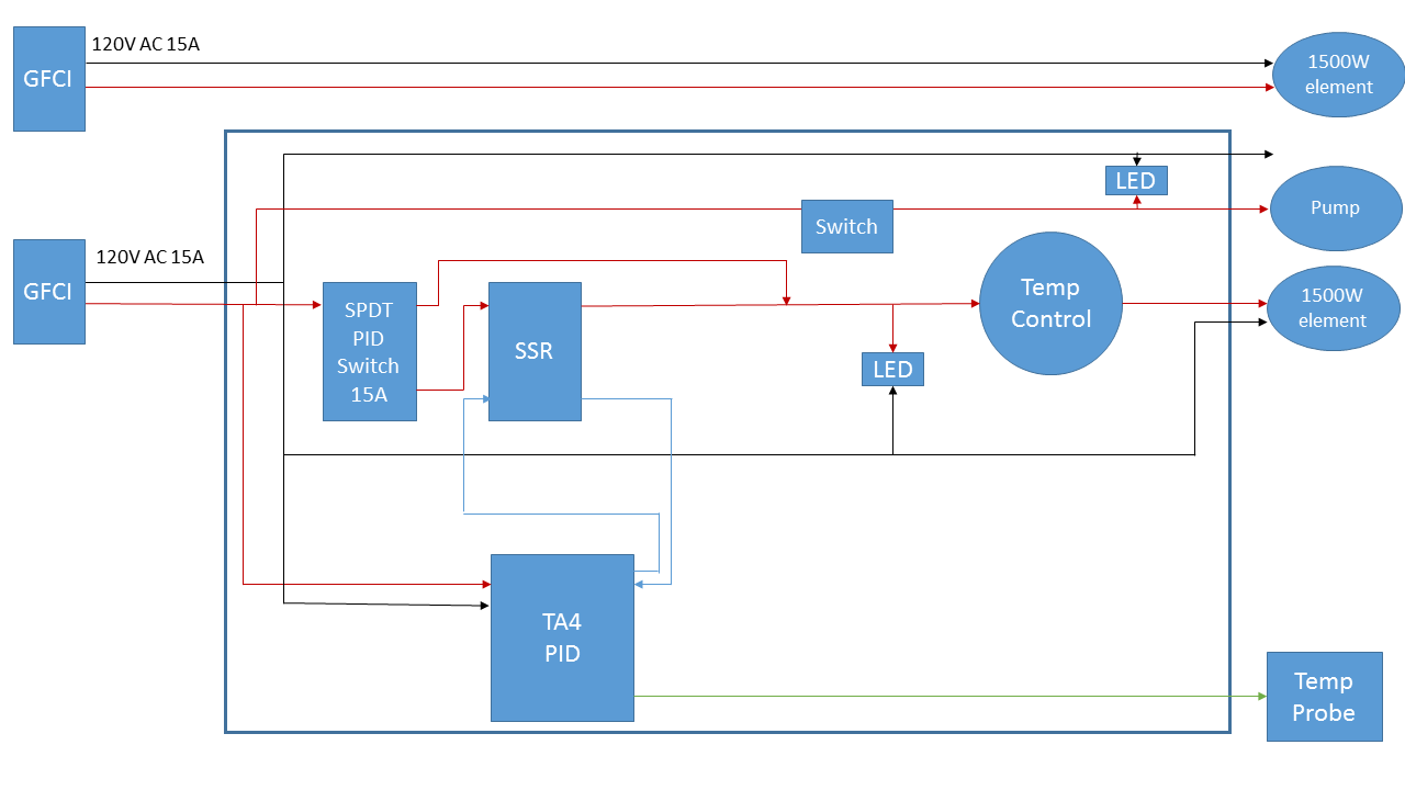
I've attached a diagram illustrating how I imagine this working - if there's anyone who feels like taking a look and letting me know if it makes sense, it would be much appreciated.

Thanks!
Electric Brewery Controller Diagram.png
 
I'm sure there's already a post addressing this, but I haven't been able to find it.

I'm designing an electric brewing controller with the following characteristics:

- Dual 120V 1500W heating elements
- Pump control
- Element 1 is straight on/off at full power
- Element 2 is able to switch from PID/SSR temperature control to manual on using a three-position on/off/on SPDT switch
- In either PID or manual mode, Element 2 also has a manual temperature control dial to adjust heat output
- LED indicator lights on all three loads (Element 1, Element 2, Pump)

I've attached a diagram illustrating how I imagine this working - if there's anyone who feels like taking a look and letting me know if it makes sense, it would be much appreciated.

Thanks!

What do you plan to use for the block labeled "Temp Control"? If you use a MyPin TD4 instead of a TA4, you have the ability to manually set the element power, without requiring a second device for that function. An even better option (at higher cost) is the Auber Instruments EZBoil (DSPR120.) It replaces both the PID and a manual power controller (with easy knob adjustment of the output power.).

The LED indicator lights need to be wired between the hot and neutral lines, in parallel with the load they are monitoring. You show them wired in series, and they will not work that way (they may light, but they will limit the current so that essentially zero power is delivered to the load.)

I would not switch the power to the PID, but rather have it on whenever the panel is plugged in. You want the PID powered so that you can make sure it is set correctly, before any power is switched on to the element. If your panel is going to be hard wired to the supply, then a separate switch for the PID is in order.

Brew on :mug:
 
Thanks for the reply!

I actually purchased the TA4 before I realized that it didn't provide manual element control, so I'm working with that. I am planning on using this as the manual temperature controller.

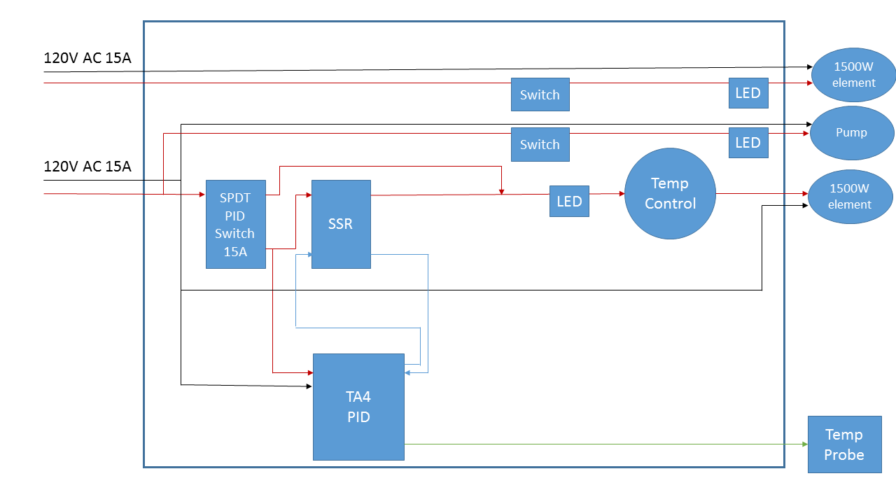
What you say about the power to the PID and the LED connections makes perfect sense - I've updated my diagram (attached).

I am not intending to hard-wire this as a panel, partly because I'd like to be able to take it outside on nice days, or over to a friend's place to brew. It will be plugged into two separate GFCI-protected circuits. Looking at my design again, I've also pulled the second circuit out of the box - it was just complicating the design. Since I will be using GFCI outlets anyway, is there any reason I can't use the "test" and "reset" buttons on the GFCI as an on/off switch for the second element?

Electric Brewery Controller Diagram v2.png
 
Last edited by a moderator:
Thanks for the reply!

I actually purchased the TA4 before I realized that it didn't provide manual element control, so I'm working with that. I am planning on using this as the manual temperature controller.

What you say about the power to the PID and the LED connections makes perfect sense - I've updated my diagram (attached).

I am not intending to hard-wire this as a panel, partly because I'd like to be able to take it outside on nice days, or over to a friend's place to brew. It will be plugged into two separate GFCI-protected circuits. Looking at my design again, I've also pulled the second circuit out of the box - it was just complicating the design. Since I will be using GFCI outlets anyway, is there any reason I can't use the "test" and "reset" buttons on the GFCI as an on/off switch for the second element?

That's better, and should work as drawn. Although I don't know enough about the contact design inside GFCI's to bless using the Test and Reset buttons for routine switching. Personally, I would put a switch on the non-controlled element power feed. I definitely wouldn't live plug/unplug it because of arcing at the outlet from the high current. Live plugging/unplugging the PID is not an issue since it only draws a small fraction of an amp.

Brew on :mug:
 
Last edited by a moderator:
My initial thought is that if you are going through all the effort to build this, you might as well do it right and get the correct PID. IMO, the extra $30 is worth it.

I run a dual 120v system with 3 elements and 2 PIDs. If you wanted to do the same thing as me, you could still use the non-manual PID to control a RIMS system. My first PID controls the elements 1 and 2, which are in the boil kettle. The second PID controls element 3, which is in the RIMS tube. Elements 2 and 3 are on a 3-way switch so that while the RIMS is running, I can still send power to element 1 and heat up sparge water.

Also, size all the wiring and components for 20 amps so that you can have the option of upgrading to 2000w elements.
 
Back
Top