Controller wiring problem

Homebrew Talk - Beer, Wine, Mead, & Cider Brewing Discussion Forum

Help Support Homebrew Talk - Beer, Wine, Mead, & Cider Brewing Discussion Forum:

This site may earn a commission from merchant affiliate links, including eBay, Amazon, and others.

BitterSweetBrews

Tim Trabold
Joined
Dec 9, 2014
Messages
453
Reaction score
103
Location
Omaha
I am having a weird problem. I am building a third brew controller (220 Volt) The issue is that the element is not turning off or cycling, even though the SSR light blinks. The temp in the kettle just keeps rising.

The PID is a MyPIN TD4-SNR and it is wired to a 40 amp Fotec SSR. I am sure they are wired properly. This is my third controller. I am sure I know what to do and have gone back to one of my other controllers for reference.

The 40 amp, Fotec SSR has control wiring from the PID to the 3-24 volt DC terminals. On the AC side of the SSR I have the source on the #1 terminal and the load on the #2 terminal. The other wire to the outlet is direct from the other hot source.

No matter what I set the PID to, using either temp control or manual control, it is running the element at full bore and just cruises by the temp I have set. i.e. If I set the temp to 90 degrees Fahrenheit it just passes 90 and would go all the way to boiling. I had 70 degree water and set the temp to 50 and it just kept heating.

The light on the SSR turns on and off with the PID cycling, but checking voltage it is still passing 100% - 220 V. I have tried three different SSRs and they all act the same. I am afraid that something is blowing the SSRs but can't for the life of me figure out what. I can't find any shorts in the wiring and would think my GFCI would blow if there were any.

I have tried to run the controller's autotune and it never stops.

Does anyone have any advice? I have spent hours on this.
 
Foteks are notorious for often being counterfeit. You may have a bad batch of them. The fact that the SSR light blinks only tells you that the PID is working correctly. A well designed control panel will have an indicator light (preferably LED) in parallel with the element. If this light does not blink in synchronization with the PID light and the SSR LED, then the SSR has failed in the on mode (most common failure mode.)

My recommendation: get some brand name SSR's like Mager, Auber (rebadged Mager), Crydom, etc., and wire an indicator light in parallel with your element (so you know what is going on.)

Edit: Another thought - inadequate cooling of SSR's makes them more prone to latching on. How are your SSR's and heatsinks mounted. Pictures are extremely helpful.

Brew on :mug:

I hadn't thought about fake SSRs. Even so, having two in a row be bad right out of the package seems out of the ordinary, but possible. I bought 4 with heat sinks and have a couple more. I will probably try a third and order some more. But, if as you say they may be counterfeit or from a bad batch, I don't expect them to be any better. I bought the MYPin in a combination pack with the PID and SSR together but have used its SSR when another one went bad on another controller.

I am thinking about getting an Auber Boil Control, but had the MYPin so I thought I would put it together and replace it later. I may just order that with an SSR.

As far as cooling the SSR goes, I totally understand. I learned that the hard way when an SSR melted on another controller I built in an HFT ammo box. I added a fan to it afterwards. On this one I have a PC Fan right next to the SSR/Heatsink blowing in.

I uploaded some pictures. It looks a little rough because I haven't been able to clean it up, since I have been troubleshooting. It is pretty tight and there are wires hanging and taped as I have disconnected to isolate. It is in an 8"x8"x6" project box.


20180504_073040[1].jpg
20180504_073044[1].jpg
20180504_073050[1].jpg
 
Last edited:
Fan location is good, but I would reroute the wires between the fan and SSR/heatsink so that they don't disturb the airflow. Even more important tho is: do you have an air exit for the air the fan is trying to push across the SSR/heatsink? If you don't have an exhaust vent, the fan as configured will do almost nothing, not even circulate air within the enclosure. Also looks like you have a contactor/relay mounted close the the downstream side of the heatsink, which could greatly reduce the air flowing across the heatsink.

Brew on :mug:
 
I tried the ssrs in another controller. None of the new ones worked. I put the known good ssr from the good controller on it. It did the same thing. I turned it off fast because it think the PID must be putting out too much voltage and burning out the SSRS. I cannot believe I had four bad SSRS. I put the good one back in the other controller and it still worked, thankfully. Boil control and pick from them. I think this is going to be a good opportunity to purchase in Auber boil controller and new SSR.
 
You might consider using a larger enclosure. It would give you room to add a second fan to have circulatory airflow, which might let your SSR get the cooling it needs, and it would give you space to add a terminal strip or buswork to eliminate the use of wire nuts. Also, I think that the inline fuse holder you are using is only rated for 48v. Would you mind posting a schematic that shows how you have your system is set up, including the wire gauges and overcurrent protection that you are using? There may be some safety issues that you have inadvertently overlooked.
 
You might consider using a larger enclosure. It would give you room to add a second fan to have circulatory airflow, which might let your SSR get the cooling it needs, and it would give you space to add a terminal strip or buswork to eliminate the use of wire nuts. Also, I think that the inline fuse holder you are using is only rated for 48v. Would you mind posting a schematic that shows how you have your system is set up, including the wire gauges and overcurrent protection that you are using? There may be some safety issues that you have inadvertently overlooked.

Yes, in retrospect a larger controller box might have been easier, but I wanted it to be compact. I have squeezed a lot into a small space and it has morphed to more than I originally planned.

I do have a 30 amp DIN terminal block connecting everything (it is hard to see), except for one set of wires split from the relay to one of the outlets and another from the grounds.

I don't think I will need another fan. This one is less than an inch from the SSR, blowing on it. I have a similar setup in another box that works great (the SSR is a couple inches away from the fan). I do need to drill some holes on the opposite side for venting. I don't think the outlets will let enough air out.

The fuse holder may be rated for 42 volts (or maybe 32) but it will have very little load. There is 14 gauge wiring on the fuse holder. I have replaced the supplied fuse with a 1 amp fuse to protect the PID. So, I don't think that load is going to be an issue. The fuse will blow long before the wiring.

I haven't drawn a schematic. I may with a video I am posting on my youtube channel.

For me this isn't rocket science. Once I have an idea of what I am trying to accomplish, I have the schematic in my head. I used 10 gauge wire on the L6/30 30amp/240v connections, 12 gauge wire on the 20amp/120V L5/20 connections, 14 gauge wire on the 5-15 NEMA outlets. The PID wires, except for power, are 24 gauge control wires to the sensor ports. Everything is wired at the same level as the devices that will load them and they are connected to the 30 amp terminal block and a 30 amp cord.
 
...
I don't think I will need another fan. This one is less than an inch from the SSR, blowing on it. I have a similar setup in another box that works great (the SSR is a couple inches away from the fan). I do need to drill some holes on the opposite side for venting. I don't think the outlets will let enough air out.

...
Fans don't move any air if there is no place for the air they are trying to move to go. You absolutely need vent holes in your enclosure (as I said previously.)

Brew on :mug:
 
You might have faulty controller. I had similar problem with INKBIRD controller. I did check all wiring and made a conclusion that controller’s relay is stocked in closed position (LED on the frond of PID was working properly, but voltage on the output of PID was constant). So i swapped controller and it fixed my problem.
 
You might have faulty controller. I had similar problem with INKBIRD controller. I did check all wiring and made a conclusion that controller’s relay is stocked in closed position (LED on the frond of PID was working properly, but voltage on the output of PID was constant). So i swapped controller and it fixed my problem.
Your scenario is not consistent with the OP's symptoms as stated in the 1st post:
"The issue is that the element is not turning off or cycling, even though the SSR light blinks."​
Since the SSR LED is blinking, that means the controller is sending out switching signals.

I would expect on an SSR output PID (like the TD4-SNR) that the output LED on the PID is driven by the same driver as the SSR output, so that if the PID output light is flashing, then the SSR output of the PID is also operating correctly. If the input side of the SSR is OK, then the LED on the SSR should flash as well. If the SSR LED is flashing, but the SSR isn't switching, then the triac in the SSR is latched up or totally failed.

In the case of a relay output PID, then the PID's output LED could be flashing (indicating that the PID circuitry is working), but the relay could have failed with welded contacts (on mode) or open/shorted coil (off mode.)

Brew on :mug:

Oh, i missed that SSR LED is blinking...
Yeah, that is definitely bad SSR.
 
Oh, i missed that SSR LED is blinking...
Yeah, that is definitely bad SSR.

Well, I thought that too. The SSR LED lights blinked, but the SSR controlled outlets stayed on. They had to be bad. I had simplified the wiring to the bare minimum. I had tried 3 SSRs I thought were good (they were new). None of them worked.

To verify if they were good or bad I then tested all three of them on another controller that works. They didn't work there either, so they are definitely bad.

Here is another wrinkle. I then put the known good SSR from the other, good controller in the new one. It also never turned off the element! I shut it down pretty fast because I suspect there is a problem in the PID that is blowing the controllers.

I am thinking that the LED and the switching are controlled independently. They are probably on different frequencies? I really have no idea. But now I think it must be the PID (which was also new).

I put the known good SSR back in its controller and thankfully, it still works there.

I ordered a new PID/SSR combination package. I got it yesterday. I hope to pull the other PID and test it them out later tonight. I also ordered a couple more spare SSRs to have around.

I will update the thread when I do this.

Thanks for the input.
 
...

I am thinking that the LED and the switching are controlled independently. They are probably on different frequencies? I really have no idea. But now I think it must be the PID (which was also new).

...
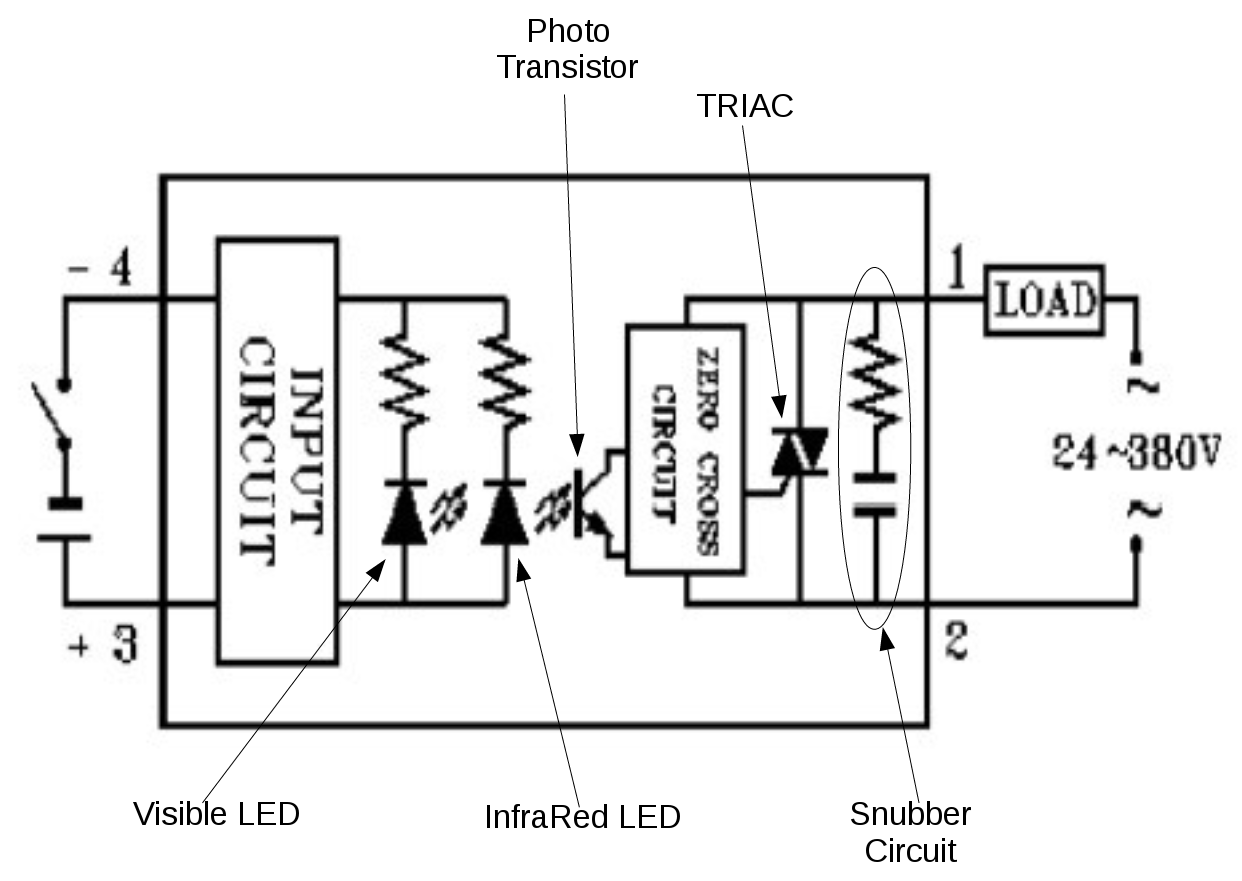
The following diagram shows what is typically inside a DC controlled, AC output SSR (the kind we use.)
SSR_internal_circuit.png

  • The "Input Circuit" provides current limiting (so that the LED's can operate safely over a wide voltage range) and reverse voltage protection (so if you connect the wires backwards you won't harm the SSR.) It may also provide some filtering to prevent electrical noise from triggering the SSR.
  • The "Visible LED" is the one on the front of the SSR that we can see.
  • The "InfraRed LED" is buried inside the body of the SSR. It's purpose is to trigger the "Photo Transistor" to conduct when the LED turns on.
  • The "Photo Transistor" detects the light given off by the IR LED, and turns on (conducts) when it detects light.
  • The "Zero Cross Circuit" detects when the AC voltage is at zero, and signals the TRIAC to turn on at every zero crossing whenever the Photo Transistor is conducting.
  • The "Snubber Circuit" absorbs the voltage spikes generated when inductive loads are switched off. It doesn't come into play for pure resistive loads - like heating elements.
Note that there is no electrical connection between the DC control circuitry, and the AC switching circuitry. A short, or other fault. in the AC circuitry will not affect the DC control circuitry. Some things to note about how things work, and fail:
  • Both LED's are turned on when voltage is applied to the DC control inputs. If the visible LED is flashing, so is the IR LED. If the IR LED were to fail as a short, It would produce no light at all, so could never trigger the photo transistor. If there is no DC voltage on the input terminals, the LED's cannot create any light. So, if the DC control circuitry fails, the AC side of the SSR cannot be turned on.
  • If the photo transistor or TRIAC fails in the open (off) mode, then the TRIAC cannot be turned on, and the AC will stay off.
  • If the photo transistor or the TRIAC fails in the shorted/closed (on) mode, then the AC cannot be turned off.
The most common failure mode for SSR's is the TRIAC failing in the on mode, either shorted (permanent) or latched (temporary.) Excess heat or current can cause the TRIAC to either latch or short out.

If the SSR light is flashing, then the controller outputs are switching correctly. An over voltage on the PID control outputs could conceivably cause the IR LED to fail, but then the SSR would be off.

Given your symptoms, the problem must be on the AC side of the internal SSR circuitry.

Brew on :mug:
 
Last edited:
I tried the ssrs in another controller. None of the new ones worked. I put the known good ssr from the good controller on it. It did the same thing. I turned it off fast because it think the PID must be putting out too much voltage and burning out the SSRS. I cannot believe I had four bad SSRS. I put the good one back in the other controller and it still worked, thankfully. Boil control and pick from them. I think this is going to be a good opportunity to purchase in Auber boil controller and new SSR.
why not just put a meter on the pid output and see if its coming on and off? (if the led is flashing It really should be)
The TD4 should work fine with a good ssr designed to work in that DC voltage range. I would double check your AC wiring something seems amiss here. if the led on the ssr goes on and off its getting proper control from the mypin and an auber unit isnt going to make lfe any easier.
I had both TD4 units and ezboil units in my last control panel. they both worked great. I actually found the TD4 easier to use but that likely because I had been using them for a couple years before the ezboil unit which seemed confusing when you tried to use its timers and alarms.

some ssrs are designed to work in different DC control volage ranges.. I think the td4 puts out like 24 v control voltage and that does work fine with the correct model and working foteks. Ive used many of them before switching to a more reliable SSR.

an easy way to check this is to just look for continuity across the blue ac wire from the input of the ssr (disconnect the wire from the ssr to prevent leakage while testing with a meter) to the element output with the panel off... I bet you have it and its why its always on.

The other possibility is you have the ground mixed up whith one of the hot connections on the element wiring and its always on at 120v power...
 
Last edited:
The following diagram shows what is typically inside a DC controlled, AC output SSR (the kind we use.)
View attachment 570394
  • The "Input Circuit" provides current limiting (so that the LED's can operate safely over a wide voltage range) and reverse voltage protection (so if you connect the wires backwards you won't harm the SSR.) It may also provide some filtering to prevent electrical noise from triggering the SSR.
  • The "Visible LED" is the one on the front of the SSR that we can see.
  • The "InfraRed LED" is buried inside the body of the SSR. It's purpose is to trigger the "Photo Transistor" to conduct when the LED turns on.
  • The "Photo Transistor" detects the light given off by the IR LED, and turns on (conducts) when it detects light.
  • The "Zero Cross Circuit" detects when the AC voltage is at zero, and signals the TRIAC to turn on at every zero crossing whenever the Photo Transistor is conducting.
  • The "Snubber Circuit" absorbs the voltage spikes generated when inductive loads are switched off. It doesn't come into play for pure resistive loads - like heating elements.
Note that there is no electrical connection between the DC control circuitry, and the AC switching circuitry. A short, or other fault. in the AC circuitry will not affect the DC control circuitry. Some things to note about how things work, and fail:
  • Both LED's are turned on when voltage is applied to the DC control inputs. If the visible LED is flashing, so is the IR LED. If the IR LED were to fail as a short, It would produce no light at all, so could never trigger the photo transistor. If there is no DC voltage on the input terminals, the LED's cannot create any light. So, if the DC control circuitry fails, the AC side of the SSR cannot be turned on.
  • If the photo transistor or TRIAC fails in the open (off) mode, then the TRIAC cannot be turned on, and the AC will stay off.
  • If the photo transistor or the TRIAC fails in the shorted/closed (on) mode, then the AC cannot be turned off.
The most common failure mode for SSR's is the TRIAC failing in the on mode, either shorted (permanent) or latched (temporary.) Excess heat or current can cause the TRIAC to either latch or short out.

If the SSR light is flashing, then the controller outputs are switching correctly. An over voltage on the PID control outputs could conceivably cause the IR LED to fail, but then the SSR would be off.

Given your symptoms, the problem must be on the AC side of the internal SSR circuitry.

Brew on :mug:

Great info.

I have checked all the wiring and verified that my terminal strip is wired correctly and nothing is crossing. I metered everything and all voltages appear correct. The PID to SSR voltage does fluctuate. I have simplified it to just the basics to troubleshoot (straight wiring, no switching through mechanical relays). I hope a new PID/SSR will fix it.


why not just put a meter on the pid output and see if its coming on and off? (if the led is flashing It really should be)
The TD4 should work fine with a good ssr designed to work in that DC voltage range. I would double check your AC wiring something seems amiss here. if the led on the ssr goes on and off its getting proper control from the mypin and an auber unit isnt going to make lfe any easier.
I had both TD4 units and ezboil units in my last control panel. they both worked great. I actually found the TD4 easier to use but that likely because I had been using them for a couple years before the ezboil unit which seemed confusing when you tried to use its timers and alarms.

some ssrs are designed to work in different DC control volage ranges.. I think the td4 puts out like 24 v control voltage and that does work fine with the correct model and working foteks. Ive used many of them before switching to a more reliable SSR.

an easy way to check this is to just look for continuity across the blue ac wire from the input of the ssr (disconnect the wire from the ssr to prevent leakage while testing with a meter) to the element output with the panel off... I bet you have it and its why its always on.

The other possibility is you have the ground mixed up whith one of the hot connections on the element wiring and its always on at 120v power...

I did put a meter on the circuits. The 208v stays on, all the time. It was getting 24V on the DC side, which fluctuated. The SSRs are FOTEK SSR-40A DA models. Input voltage is 3-32VDC, Output control 24-380VAC. I have used many of these and they have always worked well. I believe that at least one of them came with the PID (although, I might have already used that one). I really think something in the PID is blowing the SSRs.

I just bought and received a matched pair MYPIN/Fotek. I hope to install it tonight or soon, when I have some time to get back to the project. I also purchased a couple SSRs of another brand to have on hand which should be delivered by the end of the week.

I came real close to getting an EZboil. But, my checkbook won out. I got the MyPIN PID/SSR combo for <$30. The nicer EZboil and an SSR would have cost me about $90 from Auber. As you said and I agree, I have also been using MyPINs for a few years and am comfortable with them. I just couldn't bring myself to pay the extra $60, this time. Plus, if it ends up being something else, I didn't want to make the $90 gamble.

Cheers!
 
... I really think something in the PID is blowing the SSRs.

...
I don't think that is possible. Go back and study my previous post. The way the SSR's are constructed, the only thing a PID could do is blow out the circuitry on the DC control input side of the SSR (and even that would be hard to do.) If the DC control input circuitry fails, the SSR will be unable to turn on, as there is no way to trigger the photo transistor.

Brew on :mug:
 
Last edited:
The pid switches the ssr open and closed via the simple low amp dc voltage, nothing else... I know this is frustrating to hear but if the pid is switching the led on the ssr on and off its not the problem plain and simple. It has to be either all your ssrs are bad or something IS miswired.
 
OK. I know what you are saying and understand it. But, as I mentioned previously and as unlikely as it seems, I still think the PID is the root of my problems. I really believe that it is sending some sort of crossed frequency signals to the SSRs and is causing them to blow. As I said, I put a known good SSR on the PID and it did the same thing. It never turned off the element. To me, that eliminates the SSRs. Anyway, I gave up on this and moved forward.

So, last night (and into this morning) I replaced both the PID and SSR. I re-checked my troubleshooting wiring and everything was correct. Before I put everything together I tested them. They worked perfectly. I am going to toss the other PID. Using it is not worth the chance it might blow more SSRs.

After the initial testing I wired everything back together the way I initially designed it. I re-connected all my relays, switches and outlets. I also drilled some vent holes. After a few missteps with wires disconnecting and fighting the small space inside the box I got it done. I tested it again and it still works perfectly.

I finished up my video footage and will be editing it sometime soon to put on my YouTube channel.

Here are some pictures of the finished product.

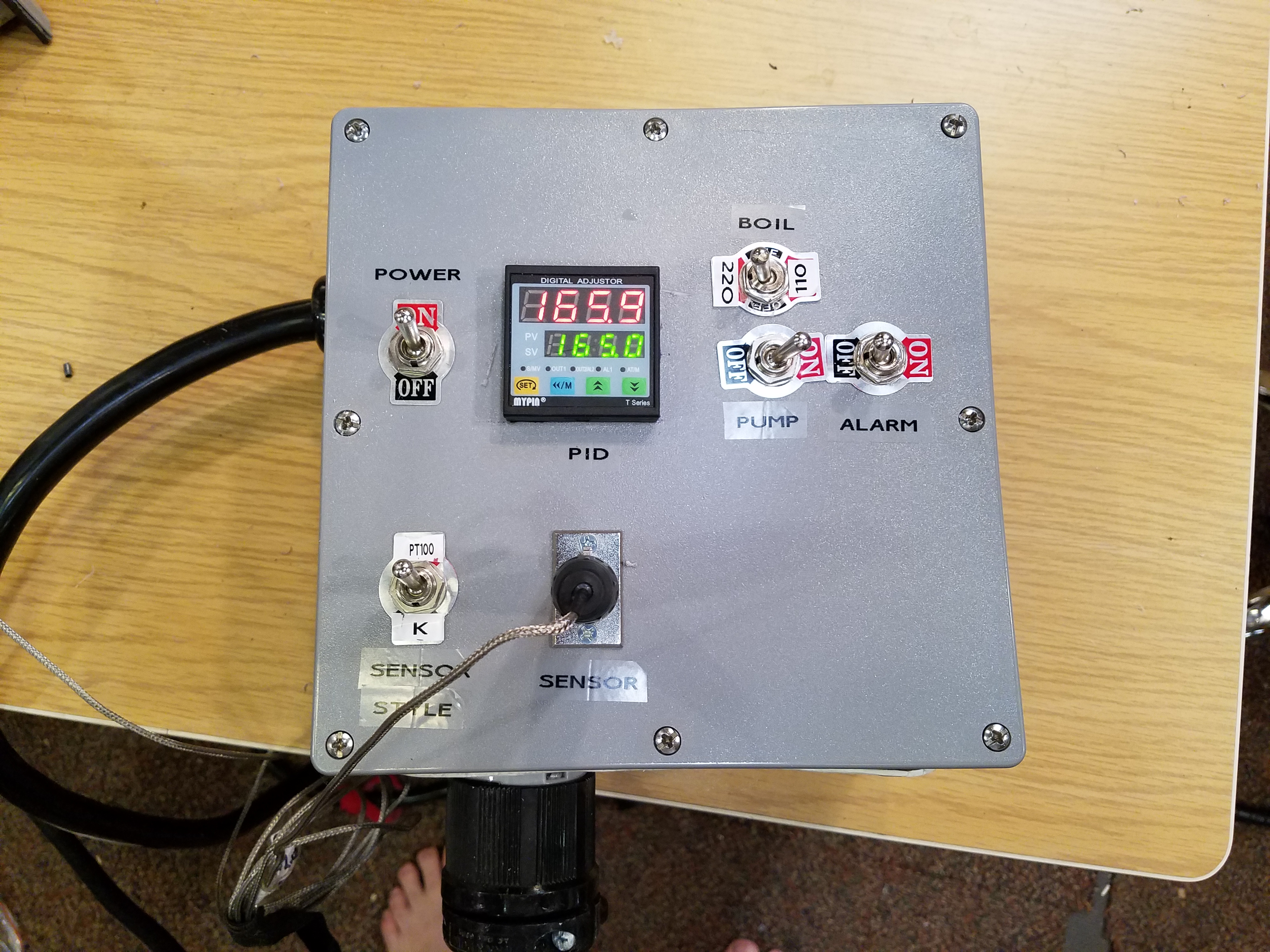
This shows all the controls:
Power Switch controlling main power relay
PID - Controls both Twist-Lock outlets.
A switch for sensor style type - PT100 or K style and the sensor outlet.
A switch controlling relays for the voltage going to the 240 V boil kettle outlet (orange). It can be either 240V or 120V. This also lets you immediately turn off power to both outlets when positioned in the middle. This can help stop boil-overs.
A switch to turn off the pump outlet.
A switch to turn on the alarm buzzer.

20180517_090540.jpg


This shows the various Outlets.

Orange - L6-30 240V Twist-Lock - This outlet can be either 240V or 120V
Black - L5-20 120V Twist-Lock - This outlet is always 120V
Red - Switched Pump Outlet
Tan - Un-Switched Outlet

20180517_090536.jpg


This shows the fan and a little hole where the alarm buzzer is mounted.

20180517_090543.jpg


This shows the where the 240V 30 Amp Dryer cord enters the case and the air vent holes. This is on the opposite side from the fan. You can really feel the air exiting.

20180517_090548.jpg


This is me testing it with one of my old kettles. It works great. I do need to run an auto-tune before I really use it.

20180517_090533.jpg


Thanks & Cheers!
Tim

Check out my YouTube Channel. Lots of Beer videos. www.youtube.com/c/timtrabold
 
Last edited:
Glad you got it sorted out.. The old pid would be easy enough to test with a cheap multimeter.

These mypins actually run completely on 24v with a power transformer in them to change the incoming power voltage.. From a logical standpoint as a technician who troubleshoots stuff like this for a living I just dont see what could cause an led indicator to work (they wont work if the polarity is wrong or the voltage is out of range) on the ssr but the ssr to not work itsself. especially when the dc control voltage is so broad on the ssr and not enough voltage would just not turn it on at all. (As doug mentioned.)

Yea, I still don't understand it. When I metered the DC going to the SSRs it did fluctuate and was never always at 24V. Anyway, with as cheap as the PIDs are and as much time as I have wasted, it just isn't worth fooling around with it any more. On to the next project.

As always, thanks for the advice and help. I really appreciate it.

One if these days I might learn how to program an Arduino and try something different.
 
Back
Top