Basics of wiring a control panel

Homebrew Talk - Beer, Wine, Mead, & Cider Brewing Discussion Forum

Help Support Homebrew Talk - Beer, Wine, Mead, & Cider Brewing Discussion Forum:

This site may earn a commission from merchant affiliate links, including eBay, Amazon, and others.

Mob_Barley

Well-Known Member
Joined
Mar 22, 2008
Messages
57
Reaction score
4
Location
Baldwin
Has anyone written a step-by-step guide to wiring a control panel for those that cannot read electrical schematics but can follow instructions well? I did not have any problems with the mechanics of designing and building my RIMS brewery, but not that it is time to wire all the components, I find myself at a disadvantage, I'm electrically challenged...

I followed some of the threads and ideas from the forum and designed a pretty complicated system with three dual gas valves with intermittent pilot ignition systems. Two are on Love TS-2 controllers and the boil kettle will simply be switched on and off. I have bought a 24VAC/75A transformer to power the valves. Now I just need some basic instructions on how to wire all the components together in the control panel.

My control panel has switches and LED lights for each pump, each burner, the HLT and MT (along with a Love TS-2 controller for each), and a main power switch. If there is a thread that goes through the whole thing without using pictures of someone's rat's nest of a panel, or complicated (for me) schematics, I can't find one. Maybe someone can direct me to the right place. Thanks for everyone's help thus far.

P1020434.JPG


P1010921.JPG


www.winning-homebrew.com
 
It's very difficult to say, really, because every control panel I've seen is different. It's not a cop out, but it's one of those things where I'd need a very good description of all the electronics, and where they are in your system.

Do you want your switches to turn the Love controllers on and off? Or do you want the switches to turn the output of the love controllers on and off?

I have thought about making a tutorial on control panel wiring, but even if I did, it would be about my control panel build. Granted others might get a few ideas or techniques, but it would be a very general "Here's how you wire a switch" kind of thing.

Is that something someone would be interested in??

Edit:
I can tell a lot from the front of your panel... If you get me a list of your parts, or a good pic of the inside of your panel, I could probably whip up a schematic you could follow. If you don't know how to read a schematic though, it might be difficult to follow.

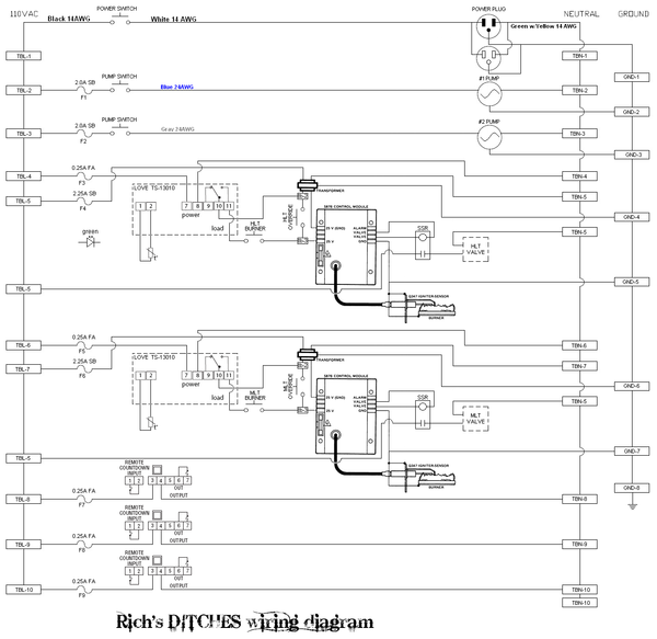
Here's mine, if it helps:
It's probably pretty complicated-looking, but look at the subsystems and it can be more clear. I think what you may be looking for is several schematics - Like "Here's the pump switch/light schematic" and "Here's another schematic for the burner switch/light wiring" and you can repeat that wiring as necessary...
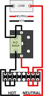
Something like this - How to wire a control panel switch:
Switch.jpg

Note on this diagram, the center connections are for the light inside of a lighted switch. In your control panel, the center connections would instead go to your separate lights...

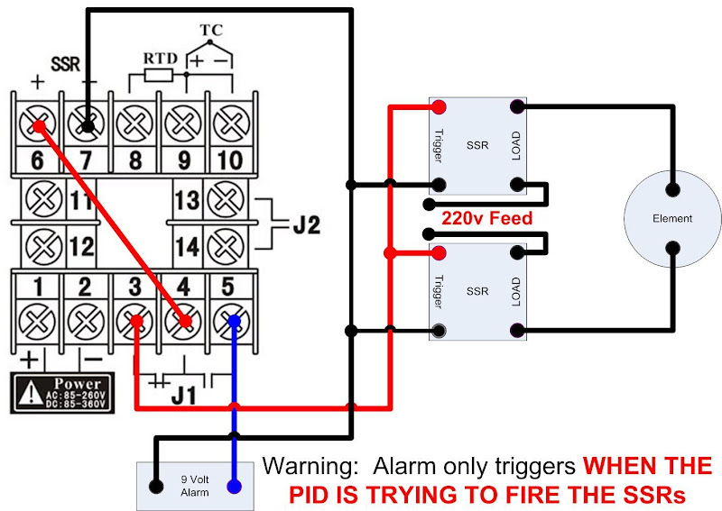
Or this - How to wire an Auber PID for electric element control:
PID%20Safety%20wiring.jpg
 
P1010932.JPG


Here is a pic of the inside of my control panel. What I'm really looking for is something like: "If you are using the Honeywell dual gas valves with intermittent pilots, you will need a 24VAC transformer with at least 50VA to power these devices. To wire them, mount the transformer inside your control panel. The transformer will have (insert typical transformer configuration). Mount two terminal strips inside your box as well. Now, (insert which components, ie. switches, Love controller, LEDs, wires from gas valves, etc.) these components will need to be powered with the 24VAC transformer. Here is how to wire the terminal block so as to connect all those components needed for the 24VAC side. (As well as some basics on wiring the switches and LED's for a common control panel). Now the main power will need to come from 120VAC, so you will need to bring in the power and wire it like this. To power your pumps and have them switched, wire them up like this ...

Well you get the point. If you can't read the symbols on an electrical schematic, then you are either forced to 1. take a "not so short course" in electrical/electronics so you can read and understand how to follow the diagrams, or 2. rely on instructions that walk you through the procedures in layman's terms with some caveats and warnings thrown in for safety...and maybe some different options so lots of people can benefit...

This is just me though. I could understand a diagram for wiring up a controller, just not a full electrical schematic with all the symbols...
 
My panel works the exact same way. My schematic will work for you. The only difference will be that you do not have timers (the bottom three items on the shematic) and I don't know which ignition modules you are using. To make things super easy, you could use the same stuff I did. It works awesome.

https://www.homebrewtalk.com/f51/superiorbrews-ditches-172520/ for the system thread.

Schematic (click for full size):


Also, I highly recommend adding an aux outlet to your panel (the receptacle in the upper right).

If you are interested I can give you the part numbers for all the electrical stuff you will need. PM me you email address if you want that info.

EDIT:: the rectangles on the left and right are positions on terminal blocks, the wave things are fuses, switches are the little upside down T's, plugs are filled int solid (power in at the top), receptacle is open (below power in). Also note that some extra terminal blocks are located int he diagram. I had to add these later as I worked out kinks but didn't want to completely redo the diagram. Also, you need some extra terminals for the lights, they patch into the circuits after the switches and return to neutral.
 
Also, you are going to have a very tough time fitting all that into that box. I suggest using the lowest rated wire you can and buying a ton of different colors and color coding the diagram.
 
After reading this thread, (https://www.homebrewtalk.com/f51/gas-temperature-control-dummies-116632/), I went with the same set-up for my HLT and MT, but to save some money, I purchased a Robertshaw 712-008 retrofit kit for my Boil Kettle. They are basically the same as far as I can tell.

I appreciate that you posted the schematic, but the thing is, I might as well be reading Greek. I can "sort of" follow along, but as far as truly understanding all the symbols, well, that's where I run into problems.

I can probably find someone that can help me locally, but since I've spent so much time building the system, I'd like to finish the project myself (plus, if something goes wrong I'll possibly be able to troubleshoot the problem if I wired it myself). Plus, getting the system wired is just the first step. I still have to test everything and make any adjustments that are required, like adjusting the gas valves, etc.
 
OK I updated the drawing a bit. Basically just use different colored wire for everything and use 24AWG for everything you can. Get lots of wire organizing stuff and try to plan ahead while getting the wires in.

Have you ever wired a panel before?
 
Unfortunately, the only way I really know how to communicate wiring advice is with a schematic.

But I'll give it a go...
For a normal "Main" power switch it would go something like this:
You should have 3 terminal strips where your main power comes in, for distributing 110 volts to the rest of your system.
The green wire connects directly to the "Ground" strip, the white connects directly to your "Neutral" strip, and the black wire should go to yout "Main power" switch. Then connect the output of your main power switch to the "Hot" terminal strip.
This way, when you turn the main "Power" switch "Off", there is no power to anything else in the box. Note: Even with the main "Power" switch off, there is still power before that switch! Don't lick that terminal ;)
Now that you have a place to get your power to all of the other things in the enclosure, you can hook up the other parts.

Lets assume you will have an outlet to plug your pump into.
Run a wire from your "Ground" terminal strip, to the ground screw on your "Pump 1" outlet.
Run a wire from the "Neutral" terminal strip, to the neutral screw on your "Pump 1" outlet.
Run a wire from the "Hot" terminal strip, to your "Pump 1" switch.
Run a wire from the output of your "Pump 1" switch, to the "Hot" screw on your "Pump 1" outlet.
Now for the "Pump 1" light:
Run a wire from the "Neutral" terminal strip, to the "Pump 1" light.
Run another wire from the output of your "Pump 1" switch, to the other terminal on the light.

Now, when you turn on the "Pump 1" switch, it will provide power to both the "Pump 1 Outlet", and the "Pump 1 light"
 
Just look at one wire at a time in the schematic. It is just follow the dots. My post above lays out what the symbols mean. And almost everything is labeled. The left terminal blocks are hot, the TBN terminal blocks are neutral (white) and the right hand ones are ground.

If you do not know about at least basic wiring, I really recommend at least getting a friend who does and having him/her by your side.

Really though it is just connect the dots with wires. If this is your first time, it is likely going to be a mess in there :D. I would buy 100' of every wire color you can in 24AWG stranded, and 50' of black, white, and green in 14AWG stranded. Lots of tie downs and zip ties.
 
This gives me a place to start. I've done some wiring around the house, after reading a basic wiring book, but I've never wired a panel before. I'll take both posts and see if I can follow along on the schematic.

After looking at the schematic, I see you have fuses and overrides built in. Are they necessary or "nice to have"? Also, the SSR (I'm assuming it means solid state relay), I didn't know I'd need one of those either. I guess I need to rethink this and do some more research before I jump in.

Thanks again...
 
This gives me a place to start. I've done some wiring around the house, after reading a basic wiring book, but I've never wired a panel before. I'll take both posts and see if I can follow along on the schematic. Thanks for your help.

If anyone decides to do a full blown "layman's" guide to wiring a panel, I'd like to put it on the DIY section of my website. I'm getting around 5-6000 visitors per month (not much compared to this site but OK for only being online a year) so maybe it will help others get over their electrical impotency...for lack of a better word for it.

Thanks again.

What you are asking for is next to impossible because almost every control panel is different. We really don't even know what you plan for your panel. Even if we did the best we could do is draw a schematic for you.
 
I guess I'm out of my element here. Ya'll trying to simplify this for me is like trying to explain to a newbie why he can't do a double decoction mash with a Mr. Beer kit. I appreciate your efforts though. I think I'll be better off taking Boerderij_Kabouter's schematic to someone that is qualified and have him do the wiring with me watching. Thanks again...
 
Hmmm... maybe I misunderstood your switches. I thought the two top switches ran the HLT and MLT burners via the controllers, and the three bottom switches were overrides so you could switch the burners on/off manually.

Fuses, yes you really should have fuses.

You would not need the SSRs for the controls you have. My control output is 24 VAC and the gas valves are 120VAC, hence the SSR.
 
I was looking at the burner control diagram here and thought that the gas valves were using the 24VAC from the ignition module...

Gas_Control.jpg


I think I have that video on my home page, here. So that's you in the sports coat and green t-shirt?
 
Another problem I'm having is that I purchased the raw frame with the control panel from someone else (who was getting married and needed the money)...so I don't know what his original thoughts were when he designed the control panel. I'm pretty much stuck with what I have and have to make it work. I don't even know if he designed it to be used with the gas valves and intermittent pilots I have installed, he may have designed it for asco valves...which may or may not cause me any problems...
 
I'm curious,
Do you have a flow diagram of your hard-plumbing? I'm hopefully going to get into a bunch of stainless 1/2" hard line, and I'm thinking about hard plumbing.

I think I just asked you for a schematic! :drunk:
 
Haha... Sweetsounds- you should really consider getting one of these if you want to do the bends.

Swagelok MS-HTB-8

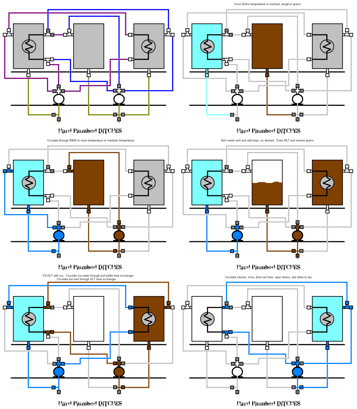
What kind of system do you have? Here is my schematic:

Hard_DITCHES.gif


and bend layout:

Plumbing_routing_Back_view_.bmp

Thanks :D
Oh, I will get a bender, but probably not the Swaglok one - I see others much like it for $25 or so...

Mine is going to be a 3 vessel HERMS from 2 20g Boilermakers, and a 5 gallon HLT/HERMS - So very similar to yours.
Thanks for the drawing!
 
I would research the bender before buying it. That tubing isn't free (unless you got your free). From my research it sounded pretty much like most benders will give you fits and/or stretch, ripple, kink or otherwise foul the tubing. The thing about the Swagelok one is they are always on eBay and always go for around the same price. So likely it will only cost you shipping costs and you might even make some money on the deal...

All I know is that the S bender does a great job with perfect bends and was pretty easy to figure out. There is a lot of skill involved and laying out the bends is crazy complicated. It took my about 10 hours to do all my bends, but they turned out pretty good IMO.

You're probably right - I won't get hurt buying the right one...

I like bending :D
DSC_5802.JPG

DSC_5850.JPG
 
I first bought a set of Ridgid 400 series tubing benders without doing any research. The 1/2" retails for $90 or so.
36132.jpg


After hearing that they wouldn't work well for stainless tubing, I did some research and found the Ridgid model 358 geared ratchet benders and bought them. This one retails for $305 or so.
Geared_Ratchet_Tube_Bender_3C.jpg


The Ridgid Model 358, meant for stainless tubing, had a Huge bend radius of 3" vs. a 1.5" radius for the 408 benders meant for copper. I tried them first and didn't have any problems at all. Granted the swagelok benders would be my first choice but they were in the $150 range on ebay and I got three sizes of benders for less than that (1/4", 3/8", and 1/2"). Some of the 180° bends were difficult but not impossible, it just took a little maneuvering to get them to bend the stainless tubing that much. I think I'll put the geared ratcheting benders on ebay since I never used them.
 
Back
Top