Auber 2532 alarm wiring with indicator light

Homebrew Talk - Beer, Wine, Mead, & Cider Brewing Discussion Forum

Help Support Homebrew Talk - Beer, Wine, Mead, & Cider Brewing Discussion Forum:

This site may earn a commission from merchant affiliate links, including eBay, Amazon, and others.

summerofgeorge

Well-Known Member
Joined
Feb 22, 2008
Messages
376
Reaction score
14
Location
Mount Laurel
I'd like to have a light on my panel that lights up when any of the alarm switches are closed. Then when the alarm condition is met, the alarm will sound. I hacked up one of Kal's diagrams but I'm not sure if it will work. I don't know exactly what pin 13 on the PID does. My interpretation is that it's the power source for the external alarm but is NO. When the alarm condition is met, it's closed and power goes to the buzzer.

While I'm asking, do you think this is unnecessary feature? My thinking is that the buzzer has a built in light so I don't really need both the light/buzzer combo and a separate light. With the alarm active light, I can easily see that the buzzer is set to go off.

Here's my attempt at wiring this:
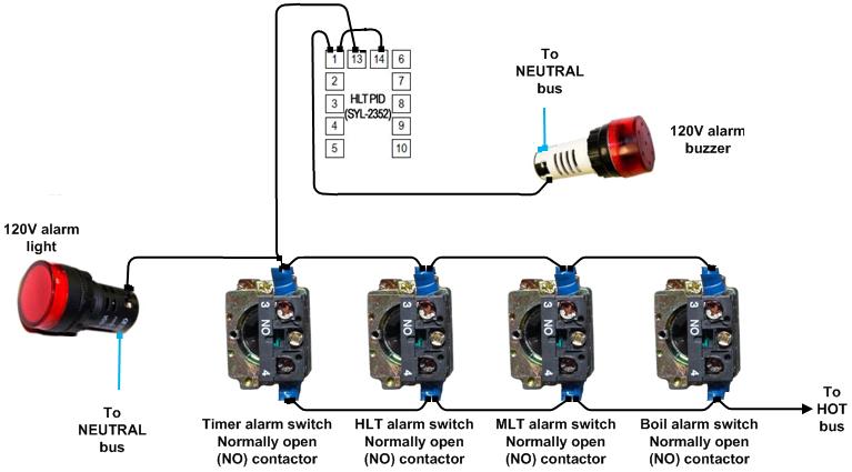
alarmbuzzerwiring.jpg
 
The way you have that drawn means if ANY switch is on ALL alarms are active. You've essentially turned 4 switches in to one. Each switch should be isolated from the others on the PID/Timer side.

The first thing that comes to my head is leaving Kal's schematic in tact and using a DPST illuminated pushbutton switch (like the ones from Auber). Now you could switch the alarm power source and illuminate the light. (This would replace the alarm LED). The buzzer wiring would remain the same.

Someone may come up with a better design solution though.
 
Thanks man...now that you pointed it out, it's pretty obvious that my wiring was wrong. I thought using DPST switches might be the easiest but I was trying to work with what I already have. I guess I could get some NO blocks to add to my switches. Or just get rid of the light since it's not really serving a purpose.
 
I got rid of the light myself, for the same reason. Since the buzzer has a light in it, I just didn't need it. I even got a little crazier and added a buzzer for each alarm. Unnecessary? Yes. Useful to me? Yes. I had plenty of room and the buzzers were so cheap I bought enough to have one per PID/Timer
20120322_184111-1.jpg
 
I'm glad I found this thread. It is close to what I did on my panel up top. I need to figure out exactly how to wire my alarms.

With the picture in the first post I have two PIDs / two Alarm switches / one AlarmBuzzer light. How would I wire that correctly?

I will try to post a picture of the front panel.
 
This is how I wired my alarms and they work for how I want to use them (looks like you were looking for something a bit different though):


Basically all I do is hold set and set AL1 to the value I want. Then I flip the switch to the on position on my panel, then when they fire I turn the alarm to off. This was how Auberins suggested that I wire them.

a.jpg
 
CidahMastah said:
This is how I wired my alarms and they work for how I want to use them (looks like you were looking for something a bit different though):

Basically all I do is hold set and set AL1 to the value I want. Then I flip the switch to the on position on my panel, then when they fire I turn the alarm to off. This was how Auberins suggested that I wire them.

That's how I have them wired. I'm wondering one of two things, either I don't have them chained properly or I don't completely know how to set the alarm on the pid. Does anyone know how I should properly connect both PIDs and switches to run one buzzer?
 
That's how I have them wired. I'm wondering one of two things, either I don't have them chained properly or I don't completely know how to set the alarm on the pid. Does anyone know how I should properly connect both PIDs and switches to run one buzzer?

It sounds like you're trying to set things up like Kal did (minus the timer). The diagram below is from Kal's site (http://www.theelectricbrewery.com/control-panel-part-2?page=12). If this is what you're trying to do, just get rid of the timer, reset button and separate alarm light.

alarmwiring.jpg
 
Turns out I already had everything wired correctly. It was the typical user error! That was my second thought, but I had to figure out what the error was.

It turns out I was over thinking(or under thinking might be more appropriate) the alarm function on the pid. When I would get to that setting on the pid I would place the decimal, after adjusting the numbers, between the last two digits thinking it would set it there. For example, 150.0 when actually I was setting it to read 1500. No wonder the alarm wouldn't sound. I didn't realize you could get rid of the first digit in the sequence.

Oh well, at least it's fully functional. In all fairness it has only been that way for about 3 days. I have a lot to learn about the controller still. Thanks to those who offered suggestions.

...and sorry summerofgeorge for invading your thread.
 
Back
Top