Arduino and Pump Issues

Homebrew Talk - Beer, Wine, Mead, & Cider Brewing Discussion Forum

Help Support Homebrew Talk - Beer, Wine, Mead, & Cider Brewing Discussion Forum:

This site may earn a commission from merchant affiliate links, including eBay, Amazon, and others.

ryan_george

Supporting Member
HBT Supporter
Joined
Jul 23, 2009
Messages
227
Reaction score
29
Location
Fergus
Hey all,

I have this very frustrating issue with my Arduino controlled electric brew system. I use a PC with a C# interface to communicate over serial with the arduino to send commands such as desired temperatures and to enabled/disable elements, contactors, etc.

Well, there are actually 2 problems but I assume they are related....

Issue 1: The power to my March pump is fed through the main control panel (so it is GFCI protected) where the arduino and all low-voltage components are also mounted. When I manually turn the pump on (with a physical switch located by the pump), 90% of the time the arduino loses connection with the PC and I get serial write errors. This is very frustrating as I have to then unplug the USB connection to arduino, restart my C# program, and start over again....
I assume this is due to some sort of electromagnetic interference or something similar....I have tried to keep the low voltage micro-controlled components separate from the high voltage/current lines (see pic below).

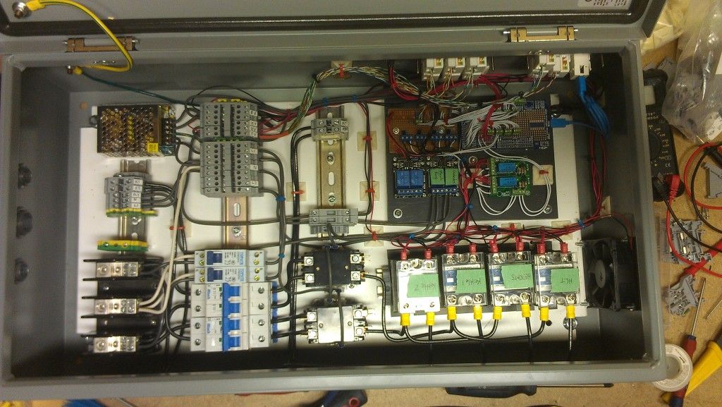
Control panel pic (this pic is not in the final state). You can see the arduino and relays mounted in the upper right, where my USB connection to the PC also is. On the far left you see the un-terminated terminal blocks where my pump gets power from, which are sent out through those conduit fittings. Main power feed (from separate 50A Spa panel) is on the lower left at those large terminals, which also enters from that side through conduit.


Issue #2: Very similar to issue #1. I have a "main power" button on my program that sends a signal to a relay to energize the two contactors that feed my elements. The relay is opto-isolated so I assume there is no interaction between the high voltage side and low voltage side of this relay. About 50% of the time when I energize/de-energize the contactors, I get the same communication fault between the arduino and PC.

This same problem existed on my previous control panel, which was an entirely different built with a rats nest of wires. I had assumed the problem was due to the messy wiring... But apparently not.

The arduino is powered from a separate 12 V power supply so it does not rely on the power from the USB connection.

I've tried searching all over for this issue but I have come up empty handed. Has anyone dealt with something like this?
 
The arduino is powered from a separate 12 V power supply so it does not rely on the power from the USB connection.

but what is THAT 12v supply powered by? probably the same power line as the pumps are on, right? what gauge and length of wire feeds your whole system, and what is your total system draw?


i had a similar issue on my arduino controlled kegerator. what fixed it was to beef up the incoming supply line to eliminate the voltage sag caused by the compressor and pump kicking on, and to further separate high and low voltages.

I was running it from a somewhat flimsy extension cord, which should have been adequate to power everything, but was causing the voltage to drop enough that the arduino reset (as best i could figure with just a multimeter, i dont have an o-scope here). i upgraded the cord from 14 or 16 gauge to a nice 12 gauge.

also the arduino was run off some random unregulated 9v 1A wall-wort style power supply i found, and i put a few large capacitors between the power supply output and the arduino input to pickup any power sags. has been working fine ever since.
 
audger said:
also the arduino was run off some random unregulated 9v 1A wall-wort style power supply i found, and i put a few large capacitors between the power supply output and the arduino input to pickup any power sags. has been working fine ever since.

Adding capacitors is easy and cheap and what I would try first. To be more specific you want to connect one side of the cap to the arduino ground and the other to the 12V input power. If you use an electrolytic or tantalum cap make sure your polarity is correct. You may have to play around with different amounts of capacitance. Too little and your problem will still exist. Too much and the 12V power supply may go unstable.
 
but what is THAT 12v supply powered by? probably the same power line as the pumps are on, right? what gauge and length of wire feeds your whole system, and what is your total system draw?


i had a similar issue on my arduino controlled kegerator. what fixed it was to beef up the incoming supply line to eliminate the voltage sag caused by the compressor and pump kicking on, and to further separate high and low voltages.

I was running it from a somewhat flimsy extension cord, which should have been adequate to power everything, but was causing the voltage to drop enough that the arduino reset (as best i could figure with just a multimeter, i dont have an o-scope here). i upgraded the cord from 14 or 16 gauge to a nice 12 gauge.

also the arduino was run off some random unregulated 9v 1A wall-wort style power supply i found, and i put a few large capacitors between the power supply output and the arduino input to pickup any power sags. has been working fine ever since.

Yes, the 12 V supply is also powered from the same main circuit. I have 6 gauge wire running from the breaker panel to the Spa/control panel (about 50' or so). After the power reaches my control panel it is immediately split into two 240 V 30 A circuits on 10 gauge wire, and two 120 V 15 A circuits on 14 gauge wire. Total system draw will vary, but it likely peaks around 48 A or so when everything is running full tilt. Note that this communication breakdown will happen when all elements are off or on, it doesn't make a difference.

I believe the arduino is powered with 22 or 24 gauge wire. Should I upsize this?

I hadn't thought that it would be a voltage spike/drop that would cause this problem. I'll look into adding a capacitor to it and see if that helps at all. What value of capacitor would you suggest as a starting point?
 
I'm not doubting the diagnosis, but would like more explanation as this confuses me. Turning the pump on causes enough voltage drop on his main line to cause the 12v power supply to drop enough to reset the Arduino?
Shouldn't the Arduino run fine down to around 7v, since it's regulated down to 5v or 3.3v at that point anyways? If the 300 watt pump motor is enough to cause a voltage drop, why aren't the 5000 watt elements causing the same problem every second?

OP is "ahead" of me on his build, I'd like to not experience this problem when I get to this point.
 
I am also unsure if the voltage drop is actually the problem. Like you mention, I'd assume there would be a similar problem each time the elements fired. This is why my original thoughts were some sort of EMI.

But, I've still got to add the capacitor to rule that out.
 
Beautiful panel, nice work!
I recommend trying to isolate where the problem area is located. Try and determine if the Arduino is being reset/crashed or if it's only the usb/serial communications that are being interrupted. Maybe you could program an output to flash on and off and see if it continues after you loose communications. Low current signal lines are very susceptible to interference if not properly shielded. Are there any resets signal lines going into your Arduino that could be falsely triggered by interference?
 
I have fairly good confidence that the arduino is not resetting. The very first time this happened I had the PC program crash (due to the communication fault) but my elements were still firing away! I had to write some code in the arduino to turn off all outputs if it has not heard back from the PC for a given amount of time, for safety purposes. I do not have any external wires which control a manual reset. Only the button on the board itself.

In terms of interference.... Could ANY I/O wire on the arduino potentially pick up some EMI and mess up other aspects of the board? For instance, would my signal wire controlling the contactor relay have the ability to pick up interference and screw up the serial connection? I do not have the knowledge of micro-controllers on this level....

In the control panel pic, on the upper right is where the arduino is and the blue coiled wire is a USB line connected to a keystone jack. I connect my PC to the other side of this jack with a USB. There are no high voltage wires in that area.

Could a shield simply be a piece of grounded sheet aluminum or steel that "boxes" in all of the low voltage components? Would this be sufficient?
 
Relays without snubber circuits (diode or capacitor) can give a voltage spike feedback when turned off, which could confuse the Arduino. It is safer to use opto isolators between the Atmel cpu and loads to eliminate that type of problem. There are DIP mount BI-FET isolators from littlefuse that have current ratings up to 2 amps and will work with both AC and DC loads and effectively keep the cpu and loads apart. They can be mounted on some perf board and wired between cpu and loads fairly easily, and the cost is not prohibitive.
Shame on you for not using try-catch loop for communications, and a recovery routine to restore connection to the Arduino when this happens.
Have been there and done that with other hardware with the C# applications for the automated brewing system, and IO development boards that I am working on. You need something that can recover from all the possible malfunctions, PC crash, Arduino crash, cable unplugged, etc..
 
kladue,

These are the relays I use between the arduino and contactor coils: http://arduino-info.wikispaces.com/RelayIsolation
From their description of how these work, I would have assumed it would be perfect for this application (contactor coils)! But my pump is currently just manually controlled, so this doesn't really explain that issue....

I hadn't considered trying to programmatically reconnect the arduino. I need to physically unplug and reconnect the arduino to re-establish the communication. I suppose I could look into finding some code for this.

However, ideally, it would be nice to solve the root of this issue, rather than add band-aid solutions.
 
If the capacitor doesn't work, would you be willing to temporarily disconnect the pump from the contactor and trying it? It seems to me that would isolate the problem to either the pump motor starting, or the relay & contactor firing. Then you could focus your efforts accordingly.
 
ryan_george said:
kladue,

These are the relays I use between the arduino and contactor coils: http://arduino-info.wikispaces.com/RelayIsolation
From their description of how these work, I would have assumed it would be perfect for this application (contactor coils)! But my pump is currently just manually controlled, so this doesn't really explain that issue....

I hadn't considered trying to programmatically reconnect the arduino. I need to physically unplug and reconnect the arduino to re-establish the communication. I suppose I could look into finding some code for this.

However, ideally, it would be nice to solve the root of this issue, rather than add band-aid solutions.

I agree you should try to find the root cause of the problem but I wouldn't consider the SW fix the kladue is proposing as a band-aid fix. It is really a way to make your code more robust and less fragile. Any time you are communicating between two devices you should try to anticipate communication loss and be able to gracefully handle it in a way that the end user is minimally impacted from it. Depending on the bus protocol and architecture of the communication link you can do things like add timeouts while waiting for a response from the slave device and retrying multiple times before escalating to the next level. The next level would be to try to go back to reinitializing the communication link.

I previously worked for a company that developed its own proprietary wireless protocol for building automation sensors. Without timeouts, retries and rediscovering the network our dropped packet loss would have been >10% instead of the <0.1% that we typically saw. Even on a smaller scale we implemented the same type of fallbacks with the I2C bus between the microcontroller and the LCD controller.
 
If the capacitor doesn't work, would you be willing to temporarily disconnect the pump from the contactor and trying it? It seems to me that would isolate the problem to either the pump motor starting, or the relay & contactor firing. Then you could focus your efforts accordingly.

Currently they both (pump and contactor) are causing the issue independently. The contactor only feeds the elements (upstream of the SSRs).
The pump is fed directly from my mains bus in the panel.

I agree you should try to find the root cause of the problem but I wouldn't consider the SW fix the kladue is proposing as a band-aid fix. It is really a way to make your code more robust and less fragile. Any time you are communicating between two devices you should try to anticipate communication loss and be able to gracefully handle it in a way that the end user is minimally impacted from it. Depending on the bus protocol and architecture of the communication link you can do things like add timeouts while waiting for a response from the slave device and retrying multiple times before escalating to the next level. The next level would be to try to go back to reinitializing the communication link.

I previously worked for a company that developed its own proprietary wireless protocol for building automation sensors. Without timeouts, retries and rediscovering the network our dropped packet loss would have been >10% instead of the <0.1% that we typically saw. Even on a smaller scale we implemented the same type of fallbacks with the I2C bus between the microcontroller and the LCD controller.

I understand the need for robust programming for end users, but this is only me operating the equipment. And the issue I'm having is not just a temporary fault in the communication that could be overcome by waiting or retrying. Once it happens, the PC must see that the device has been disconnected and reconnected before it will start talking again.

I appreciate all of the comments and feedback! I have been too busy lately to really tackle this thing.... Hopefully soon there will be some time :drunk:
 
Just to throw in a few of my own cents here, I do seem to agree with the concept that this might be a power related issue. It seems that you might be over stressing that little 12v capacity doing inductive loads (pump turning onw, and even closing the relay are both). I can say that many power supplies skimp on the bulk capacitance, and it is easy to put a quick remedy to that simply by applying a large electrolytic cap on your arduino power input. Quick and heavy stress like these loads produce often times can overwhelm a supply and cause a brown out, think when you turn the vacuum on and the lights dim. Brownouts are very difficult to really trace because unless you have some great power management chips, or all the right bits set on the device setting it may chug along with all kinds of issues.

Just as a point of note here in my experience with many chips (though I have the least experience with atmels) and especially with the ones I have made there are quite a few different hidden power supplies within the actual chip itself. And often the core voltages are a little lower than the peripherals so in a brown out condition you may not lose the actual core and running instructions but the uart for example might go to an undetermined state. I had this issue back when implementing systems with coldfire chips that we experienced a brownout on the very bottom of acceptable input voltages (actually a little below acceptable) that only affected certain peripherals. Also this wouldn't rule out that the FTDI chip that does the uart to usb could have a less tolerant range as well.

While it is possible to have EMI, you have short runs and lots of fairly low speed and tolerant protocols here. It is possible to sheild everything, but its also a ***** to do so I would really check a few other things here first. Also, though not familiar with arduino's programming setup, I might check that you don't have some sort of port issue (highly unlikely though).

Thank you very much for this detailed explanation! This is the sort of info I was hoping someone would have :D Like I mentioned, I have no knowledge of the finer details of microprocessors and this is a great help.

Again, sorry for the slow progress, but I'm now away from home for the next week or so, so the beer will have to wait. Thanks again to all
 
Well, I was able to find time today before I leave, so I added some capacitors to the 12V line. I added 200uf and I am very pleased to say that the problem is almost gone. It seems to be significantly less sensitive to the contactors and pump turning on. If I cycle them very quickly I can still get it to crash. Perhaps this is an issue of the capacitors not being able to recharge sufficiently between cycles. I added another to get 300uf in total, which again seems to improve it but it's not entirely perfect. I have ordered some larger caps of ebay (chinese specials) and I'll try those once they get here. But for now, this looks very promising....

Cheers to everyone who has helped so far. I wouldn't have thought of this being the problem, but I'm happy that progress is being made! :mug:
 
ryan_george said:
Well, I was able to find time today before I leave, so I added some capacitors to the 12V line. I added 200uf and I am very pleased to say that the problem is almost gone. It seems to be significantly less sensitive to the contactors and pump turning on. If I cycle them very quickly I can still get it to crash. Perhaps this is an issue of the capacitors not being able to recharge sufficiently between cycles. I added another to get 300uf in total, which again seems to improve it but it's not entirely perfect. I have ordered some larger caps of ebay (chinese specials) and I'll try those once they get here. But for now, this looks very promising....

Cheers to everyone who has helped so far. I wouldn't have thought of this being the problem, but I'm happy that progress is being made! :mug:

Glad to hear that it is helping. It can take a few seconds to charge up that much capacitance fully so I am not surprised that when you cycle the pumps quickly the problem returns. Hopefully adding a few more hundred uF will solve the problem completely. If that doesn't work you could try adding an inductor, as Alien suggested, in series before the capacitors. Something in the range of 200uH would be what I would try. You would hook the inductor so the 12v output of the power supply would connect to one side of it and the other side would connect to the 12v input of the arduino. All of the power going to the arduino would go through the inductor. Do not connect it from 12v to ground like you are doing with the capacitors. This would cause the power supply to go into short circuit protection, if it has that feature.
 
Out of curiosity, is the 12VDC system floating, or is the negative side tied to AC neutral or ground?, might cause voltage differential on USB connection to another computer. Other problem could be the switching power supply is dropping out and the power level droops enough to reset the CPU.
As to the communications, it was necessary to handle communications failures of all types automatically with a more robust system that I use. In your case you might be able to fix root cause and not need the fix, but these things can come back to bite you if you do not plan for them.
 
The 12 VDC system is floating. I did not know it was acceptable (or safe) to tie the DC to the AC ground. Is this something I should do regardless?

Also, if I put the DC negative to my system ground, will this cause an issue with the GFI?
 
What kind of 12VDC power supply are you using? Iv had similar problems with my arduino when I had it powered by the sort of power supply you would find with a laptop or a dust buster or something. Getting a good quality PC PSU provided much cleaner and stable power regardless of heavy induction loads starting or stopping on the AC side
 
In the control panel pic, on the upper right is where the arduino is and the blue coiled wire is a USB line connected to a keystone jack. I connect my PC to the other side of this jack with a USB. There are no high voltage wires in that area.

Maybe the keystone jack is picking up some EMI. Have you ever tried to connect the Arduino straight to your PC using a USB cable and bypassing the keystone jack?
 
The capacitor has improved things quite a bit. I ended up with 1000 uF on the 12 V line. I did, however, find that the problem occasionally lurked up again when the laptop power supply was plugged into my brew stand (the laptop is connected via USB to the arduino). I ran a separate extension cord for the laptop power which seemed to make it disappear. The inductors have just arrived from China, so they are next on the list to add. The quest continues!
 
I'd try relocating the DC supply to that empty spot of DIN rail to avoid wire tying the low voltage line along side that AC line. Also, If you are getting EMI, go into EMI suppression wiring mode and twist all your DC wire pairs.

Did you try putting some MOVs on the contactor coils and motor like it suggested in your link?
 
Back
Top