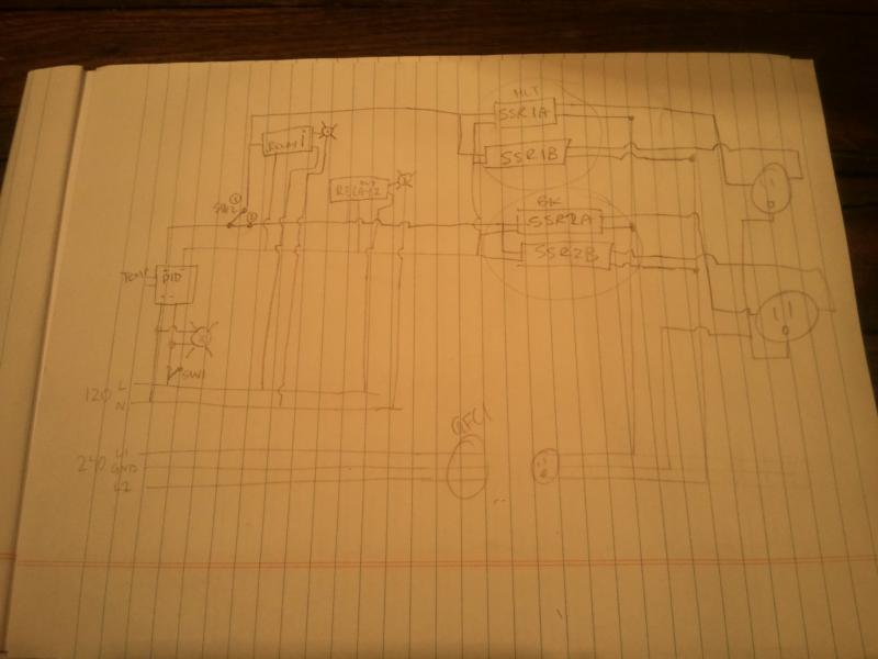
Another E-brewery design 1 PID, 2 Elements, 4 SSR's

Homebrew Talk - Beer, Wine, Mead, & Cider Brewing Discussion Forum

Help Support Homebrew Talk - Beer, Wine, Mead, & Cider Brewing Discussion Forum:

This site may earn a commission from merchant affiliate links, including eBay, Amazon, and others.

aquenne

Well-Known Member
Joined
Oct 10, 2011
Messages
231
Reaction score
17
Location
Paris
Im currently in the design phase of my ebrewery. Exciting stuff cant wait to start brewing in my basement.
If anyone has any comments or ideas to share please by all means.

Im somewhat following Kal's design but am scaling back where I can.

Here is an overview of the system im proposing, ive deviated from some of the other designs based on what parts I have on hand (ie: several SSR's, relays, etc).

Power is fed from my 100A fuse panel to a 30A fused 8/4 cable. From there im goin to install a box with a 30A 3 wire outlet (note im not using the neutral for the "power" portion of the design). I purchased a TRC 30A 10/3 GFCI cable, which i will install a similar 30A 3wire male connector on either end. This will then connect to my "power box".

I will have a 5500w 240element in both the HLT and BK. One PID will control both (manual control for the BK, the thermocouple will reside in the HLT).

Within the powerbox there will be (4) 25A 240V solid state relays.

The idea would be:

SSR-BK-1 switches Line 1 in the BK
SSR-BK-2 switches Line 2 in the BK
SSR-HLT-1 switches Line 1 in the HLT
SSR-HLT-2 switches Line 2 in the HLT

The 24V control signal from the PID will be diverted via a selector switch to either SSR-BK1 & SSR-BK2, or SSR-HLT1 & SSR-HLT2. So only 1 element can be energized at a given time.

There will be a main disconnect switch installed in the "power box".

The power for the "control box" will be fed via a 15A GFCI protected circuit. (As the 30A GFCI cable i purchased is only a 3 wire design, so no 120V). The control box will also house 2 relays which based on the PID output thru the selector switch will energize either the HLT or BK pilot light. 1 pump will also be fed using this 15A circuit and controlled via a toggle switch.

Im still determining how I can effectively kill both the 240V and 120V to the entire system with the use of a single E stop.
 
sorry for the messy schematic.. hopefully it does more to help then confuse.

IMG_20111213_181710.jpg
 
do you already have the SSRs? if not a contactor would actually cut the power and be cheaper than the ssr. The SSR can fail closed (with power on) and then your element could still be powered.
 
I do already have the SSR's.

If one were to fail with the contacts closed, techanically the element would not be powered as one leg of the 240V would theoretically be correctly turned off by the other SSR.

Ideally a double pole contactor would be a better solution, but again, already have the parts and im just trying to make best use of the limted funds while still being safe.
 
I purchased a TRC 30A 10/3 GFCI cable, which i will install a similar 30A 3wire male connector on either end. This will then connect to my "power box".

That part in red is not recommended. You don't really want a male connector to be energized. If you plug one end into the power source, the other end is a potentially lethal device.
 
Yes, good point. Hard wiring the other end of the GFCI cable directly into the power terminals in the "power box" would be a better method then.
 
That part in red is not recommended. You don't really want a male connector to be energized. If you plug one end into the power source, the other end is a potentially lethal device.

I must have skimmed right over that... sorry that should have been my first safety question.

I assume you also have a GFCI outlet on your 120V line.

I would want to unplug the 240 while cleaning transfering and what not since the power could still be live to one leg of the element.
 
I must have skimmed right over that... sorry that should have been my first safety question.

I assume you also have a GFCI outlet on your 120V line.

I would want to unplug the 240 while cleaning transfering and what not since the power could still be live to one leg of the element.

With the SSR's unenergized neither leg of the 240V would be energized. Some of the early posts were under a SSR fault, one leg could possibly have voltage present. Under normal conditions it should be safe to leave the 240 plugged in.
 
Any other comments welcome.

have the PID purchased along with all the stainless fittings. I will be going with a 1" NPT locknut vs the mcmaster carr as they do not ship to canada, and cant find anyone willing to ship one at a decent price (~50 bucks for 2 + shipping).
 
With the SSR's unenergized neither leg of the 240V would be energized. Some of the early posts were under a SSR fault, one leg could possibly have voltage present. Under normal conditions it should be safe to leave the 240 plugged in.

not exactly... an SSR is not a switch, the way I understand it its a variable resistor. even off there is usually some (albeit small) leakage current.
 
not exactly... an SSR is not a switch, the way I understand it its a variable resistor. even off there is usually some (albeit small) leakage current.

+1... personally I would put a contactor/mechanical relay with a power switch inline with the SSR. That way if the switch is off the contactor is de-energized and the line is disconnected. If you just use the SSR then in theory there will be leakage current and if the SSR were to fail it wouldn't be good.

Also the 2 SSRs isn't really necessary. What you really want is 1 contactor (2 pole) and 1 SSR.... The contactor switches BOTH lines for the 220V, while the SSR just switches one. You really don't need to have an SSR on both lines. The current is limited by one... the second one is basically just extra complexity for really no upside. Use a push button to control the coil current on the contactor and the PID to control the SSR. Does that make sense?...

Yes I fully understand what you are saying, it is what many other members have been doing. Im using the 4 SSR's because I have them.

There will be a 240V main disconnect installed in front of the entire system so when I am not physically in front of the equipment, the system would be de-energized.
 
I would still use only one ssr per element. Keep the other two for spares. Depending how well your system dissipates heat, you may need them as spares. It will be a simpler circuit with one ssr per element but that has already been mentioned.

I wonder if there is any chance that using more than one ssr per element could actually interfere with the efficient operation of the circuit? Anybody?

I can't see a reason it wouldn't work. It would add some loss to heat. I could also see a problem if they cycling rate was VERY high and there was a difference in the response time of the SSRs... (I can't explain the whole scenario if anyone is interested)... but beyond that it should really be a problem. That said... it doesn't buy you anything, and I really wouldn't trust it as a safety. I'd save the 2 SSRs (or sell them) and buy a contactor.
 
Eric,

You are spot on in regard to the heat loss. That is doubled as both SSR's will be carrying the same current load and each will heat up in the exact manner as a single SSR would.
 
I do already have the SSR's.

If one were to fail with the contacts closed, techanically the element would not be powered as one leg of the 240V would theoretically be correctly turned off by the other SSR.

Ideally a double pole contactor would be a better solution, but again, already have the parts and im just trying to make best use of the limted funds while still being safe.

If you control both sides with SSR's and one fails then you the entire circuit is sitting there with 110 VAC applied.

Why?

Because a 220V circuit is a Edison connection. This means you really have two 110V circuits that are 180 degrees out of phase with each other and you only get 220V when you connect across both circuits. The voltage from either circuit to ground is 1/2 of the 220 volts or 110 volts.

But 110V is still deadly and you need a master contactor or disconnect to protect yourself from harm.

I think he is assuming the situation where you are not applying a signal to the SSRs. In that case yes, in theory if neither has signal your 2 120V lines would be disconnected. This is a different case than the above.

I see several two cases for the SSR model...

1) 1 SSR Fails Open - Then while the other is turning on and off with the PID there would be 120V on the functional leg, and 0V on the nonfunctional leg whenever the PID is operational. When the PID is off neither leg would be live.

2) 1 SSR Fails Closed - While the PID is operating the 2nd it would work as expected, but when you shut off the PID there would still be 120V applied to the kettle via the broken SSR.

I am ignoring the double failure... I think the issue here is that with an SSR the 2nd case is actually plausible. With a contactor it isn't.
 
If you control both sides with SSR's and one fails then you the entire circuit is sitting there with 110 VAC applied.

Why?

Because a 220V circuit is a Edison connection. This means you really have two 110V circuits that are 180 degrees out of phase with each other and you only get 220V when you connect across both circuits. The voltage from either circuit to ground is 1/2 of the 220 volts or 110 volts.

But 110V is still deadly and you need a master contactor or disconnect to protect yourself from harm.

Im not quite sure I understand what ive highlighted in red.

If the SSR on line 1 of the 240V fails, closing the contacts in the relay, but SSR on line 2 continues to function. The circuit is not closed, and no current will flow. Yes if you took a voltmeter, on the terminal 1 on element and measured to ground, yes there would be voltage present, but that would be it.

Im not an electrical engineer, so I guess im not quite sure what about that is "unsafe". Voltage will be present all over the system.
 
Thank you for all the comments, im enjoying this discussion. A safe system is paramount to me, I will be using this in a house with young children (obviously they wouldnt be directly around when brewing), but the safety of the system is of upmost importance.

Ive mentioned this a few times as well. There will be a main fused disconnect and a GFCI circuit breaker in front of the 240V lines. The disconnect will be turned off when the system is not in use.
 
Im not quite sure I understand what ive highlighted in red.

If the SSR on line 1 of the 240V fails, closing the contacts in the relay, but SSR on line 2 continues to function. The circuit is not closed, and no current will flow. Yes if you took a voltmeter, on the terminal 1 on element and measured to ground, yes there would be voltage present, but that would be it.

Im not an electrical engineer, so I guess im not quite sure what about that is "unsafe". Voltage will be present all over the system.

It's not "unsafe" per say. The unsafe part comes in when you think that the circuit isn't energized or whatever during cleaning etc. Normally people use a contactor to disconnect all of the voltage from the keg while cleaning so there is no chance of getting shocked. During operation the contactor would stay on anyways thus there would always be voltage at one of the leads of the element, so you are correct that it is the same thing.

Again... the safety is more when you disconnect it with a contactor vs. a SSR and knowing that the terminals on the element are dead, vs possibly live.
 
Again... the safety is more when you disconnect it with a contactor vs. a SSR and knowing that the terminals on the element are dead, vs possibly live.

Yup. And he said he was going to basically unplug the whole thing before cleaning or anything, so I don't see any issue with not having the contactor in there.
 
If you only break one side then you have the other side's voltage across the entire circuit which is why it's extremely important to install a breaker or disconnect that opens both sides of a 220V line. I attached a quick drawing to show why.

Heater Wiring.jpg
 
If you only break one side then you have the other side's voltage across the entire circuit which is why it's extremely important to install a breaker or disconnect that opens both sides of a 220V line. I attached a quick drawing to show why.

Thanks for taking the time to draw up that graphic

That is how I understood it as well. If SSR on line 1 fails (closed), and than on the output contacts of SSR2 (which will be open), will both show voltage, but the "loop" will be open as well, IE, no current will flow. The element will not heat as there is no flow of current.

So bottom line, I dont quite see how this is "unsafe".

Again, thanks for taking the time for drawing the graphic, i think we are both on the same page with what will happen when one of the 2 SSR's fail, but not quite sure what is unsafe about what will happen when (if) that was to happen.

There will be 2 sets of 30A fuses (in main panel, and another set in a main disconnect panel), and a 30A GFCI circuit breaker as well. If under the condition where there was 120V present at thru the element, if more than 5mA (i beleive that is the ground fault rating of the interupter I have), than it will trip and both legs of the 240 will be dead.
 
Yup. And he said he was going to basically unplug the whole thing before cleaning or anything, so I don't see any issue with not having the contactor in there.

Right. Then it doesn't matter. We aren't building to industry standards here... the goal is just know your own system so you don't get shocked. :)
 
Yup. And he said he was going to basically unplug the whole thing before cleaning or anything, so I don't see any issue with not having the contactor in there.

... but then one day you decide to clean one of the kettles early while the other's still going so you can't turn on the control panel...

I'm usually sponging out excess water from my HLT while I'm boiling. I like to know that the HLT element is completely physically disconnected when I do this.

YMMV.

Kal
 
That is how I understood it as well. If SSR on line 1 fails (closed), and than on the output contacts of SSR2 (which will be open), will both show voltage, but the "loop" will be open as well, IE, no current will flow. The element will not heat as there is no flow of current.

So bottom line, I dont quite see how this is "unsafe".
It's unsafe because the element is still energized on one side. If you're in there cleaning it or something and happen to break it somehow and touch it, your body might close the circuit. (One hand on element, other on the pot which is grounded).


If under the condition where there was 120V present at thru the element, if more than 5mA (i beleive that is the ground fault rating of the interupter I have), than it will trip and both legs of the 240 will be dead.
Correct. But you shouldn't "count" on it. Make it as safe as is reasonably possible and then apply the safety things like a GFCI. Kind of like a seatbelt in your car. You don't expect to use it.

Just like your seatbelt, a GFCI shouldn't be thought of as something that makes you 100% safe. It's just extra insurance.

Kal
 
... but then one day you decide to clean one of the kettles early while the other's still going so you can't turn on the control panel...

I'm usually sponging out excess water from my HLT while I'm boiling. I like to know that the HLT element is completely physically disconnected when I do this.

YMMV.

Kal
There's always a way to mess things up. You might forget to shut off the contactor in your system or something.

He can always just unplug the kettle and not power down the whole system.
 
There's always a way to mess things up. You might forget to shut off the contactor in your system or something.

He can always just unplug the kettle and not power down the whole system.

I have come up with an idea which will allow me to quickly know when and if one of the SSR's fail.

Each of the 4 SSR's will have a pilot between the line and neutral. Therefore there will be 4 pilot lights, indicating voltage presence at both sides of the element.

If ever both pilot lights both do NOT turn off there will be a visual indicator. im sure some sort of an alarm could be wired to tell me as well.
 
and i dont want anyone to say, what if after your million cycle rated ssr fails, well the 100,000 hr pilot light could magically and mysteriously fail as well.

yes it could happen,

yes someone could drive a truck thru my front door too.

:)
 
aquenne said:
I have come up with an idea which will allow me to quickly know when and if one of the SSR's fail.

Each of the 4 SSR's will have a pilot between the line and neutral. Therefore there will be 4 pilot lights, indicating voltage presence at both sides of the element.

If ever both pilot lights both do NOT turn off there will be a visual indicator. im sure some sort of an alarm could be wired to tell me as well.

You do not need two separate lamps. If 1 of the relay fails in the closed position both of the lamps will light up. There will be a path from 1 hotline through the element and to the other lamp and then to neutral.
 
You do not need two separate lamps. If 1 of the relay fails in the closed position both of the lamps will light up. There will be a path from 1 hotline through the element and to the other lamp and then to neutral.

Actually, yes good point. A single 120V pilot light on either line to neutral would tell me there is voltage present.
 
aquenne said:
Actually, yes good point. A single 120V pilot light on either line to neutral would tell me there is voltage present.

If you choose to do this be mindful of what kind of lamp you buy. I use 120v neon indicator lamps on my system. SSRs Leak a very small amount of current even when they are open.

The leakage current is enough to make a neon lamp light up. And it will confuse the hell out of you. :D
 
So bottom line, I dont quite see how this is "unsafe".

The reason it's unsafe is it only takes 50 volts and very little current to kill you. Sure, the heater won't be hot but you will have 110VAC between every "live" wire and ground when one SSD fails. Plus you will have a full 220 VAC across the SSD that's off.

So it's better to use only one SSD and a main contactor or breaker at power input to the box. This way you always know what voltages to expect, you know you have 110VAC between every "live" wire and ground, and you won't accidentally grab onto something live.

And as far as unplugging the power cord goes? A dryer plug doesn't unplug easy and it won't take too many unplug cycles to decide to leave it plugged in while cleaning, particularly if you have to reach under or around something to unplug the cord.

Install a main breaker, disconnect or contactor on the box power input!
 
If the SSR's are operating correctly the system is as safe as it could be with a contactor.

If an SSR fails with the contacts closed. I will have an audible alarm wired as well as a pilot light to alert me that there is voltage present, at the heater when there shouldnt be.

Bottom line, im not designing this system for sale, im designing it for my own use.

And just out of curiousity, how often are you guys getting failed SSR's?
 
Hmm actually ill be in milwaukee for work in a few weeks.

Ill let you know.
 
And just out of curiousity, how often are you guys getting failed SSR's?

I had one fail on me after a year (appx 20 batches I guess). I chalked it up to the fact that my control panel had NO ventilation and the SSR got pretty hot while in use.

When I replaced the SSR, I cut a couple of holes in the box and mounted two small fans in it to blow air across the SSR heatsinks. time will tell if this helped.
 
Back
Top