mrmansfeld
Active Member
Hello everyone!
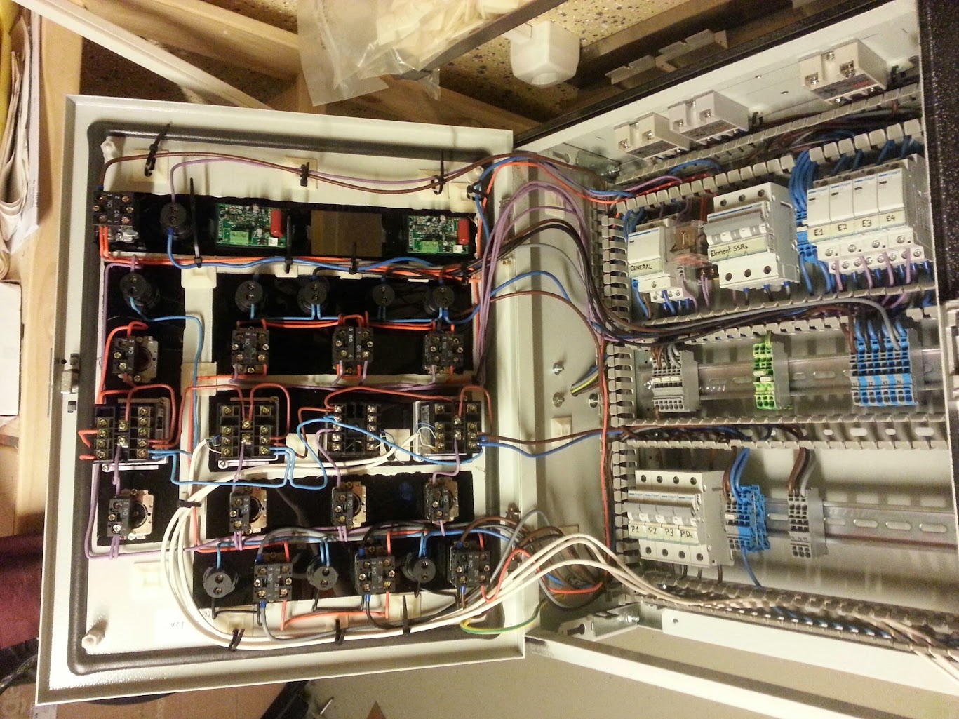
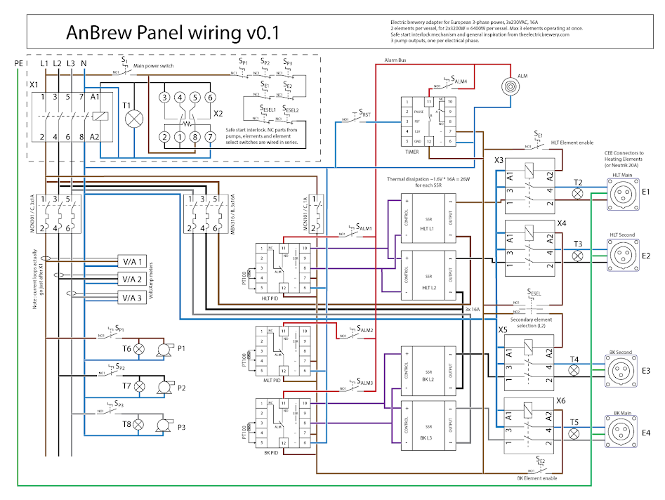
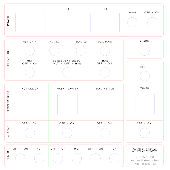
For months Ive been lurking, and drooling over Kals electric brewery instructions. Its taken me a while to wrap my head around how to adapt it to a European power network (here in Switzerland at least, we usually have fairly low amperage, and compensate with three phases at 230V relative to neutral. Ill explain more in detail when I get to the control panel / heating element part)
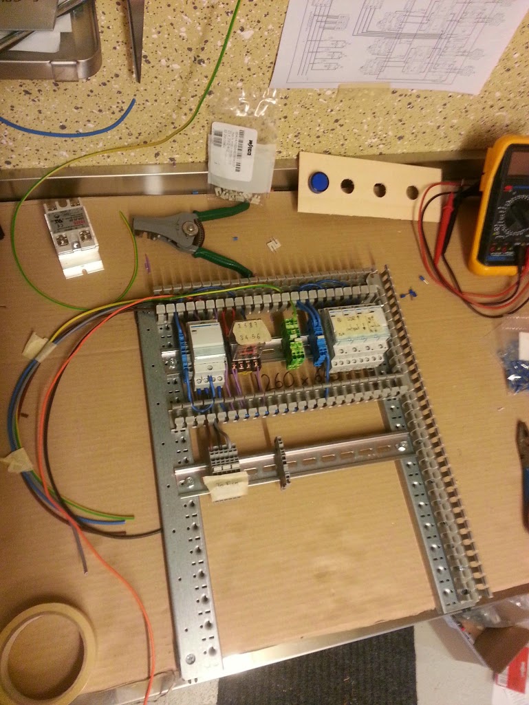
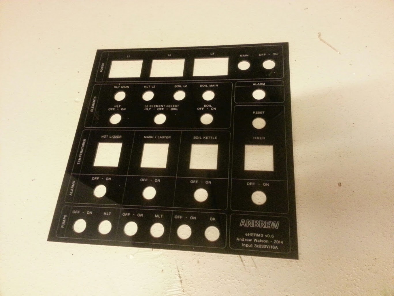
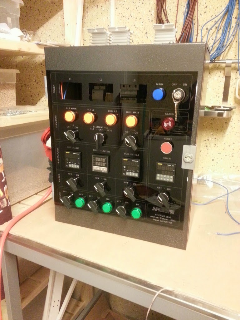
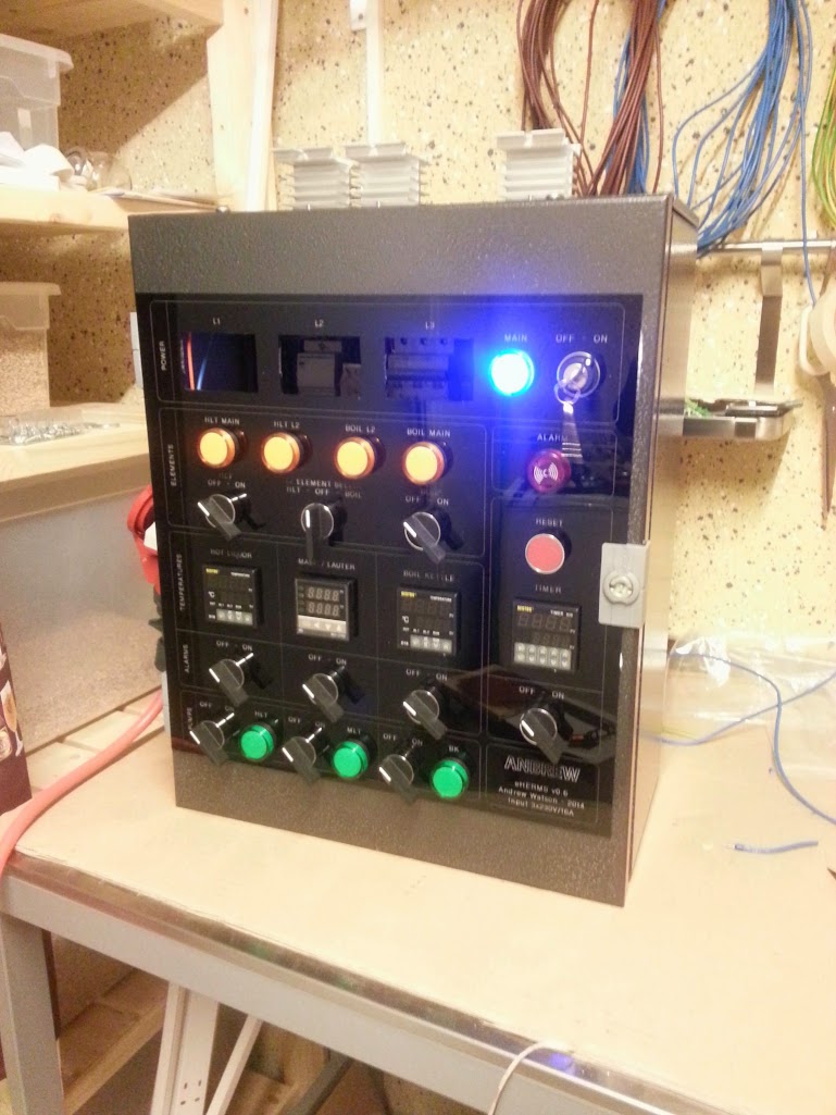
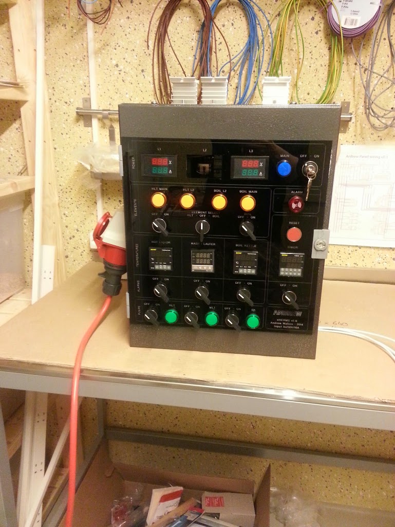
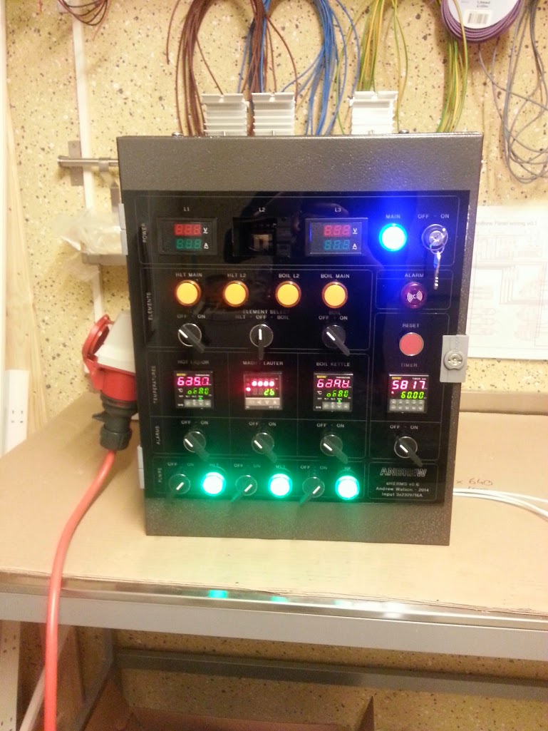
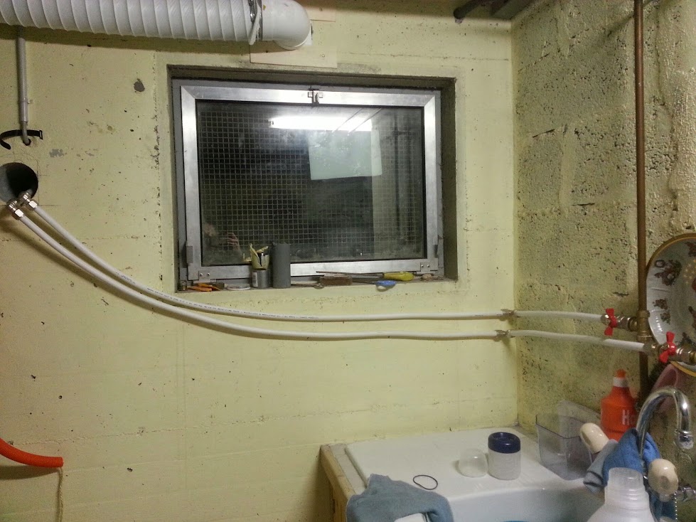
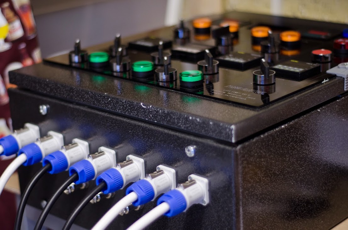
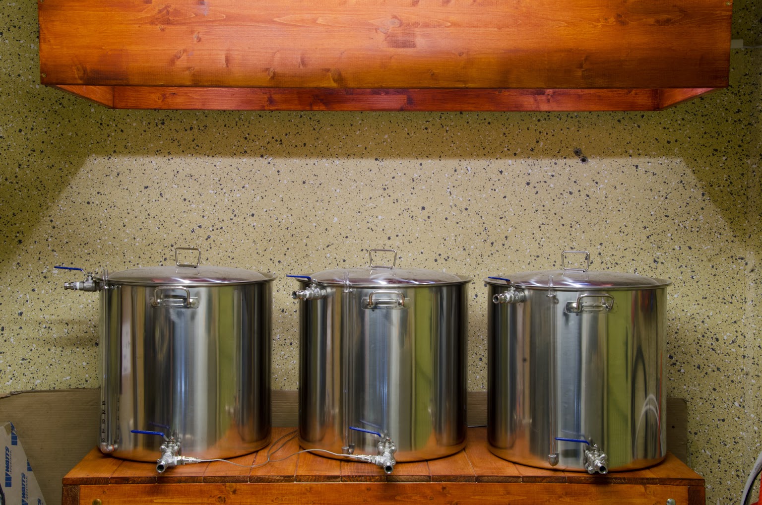
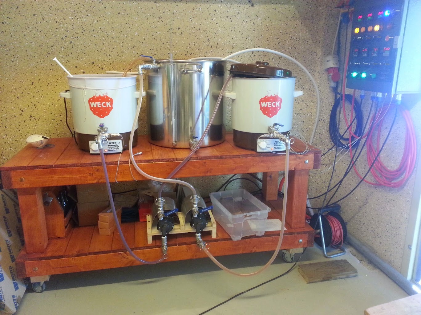
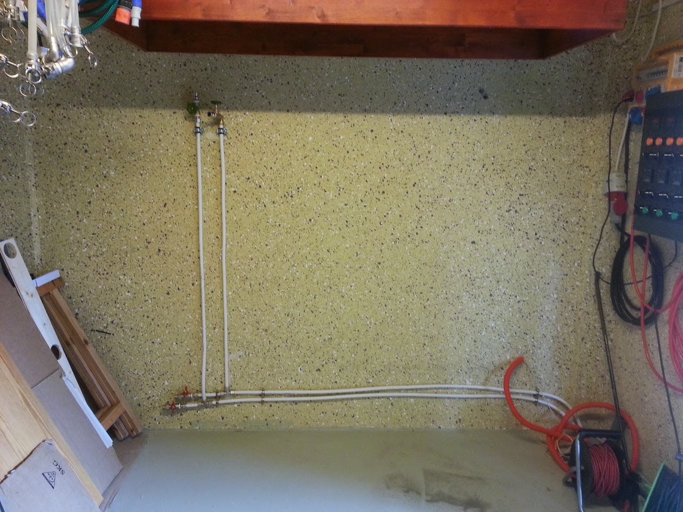
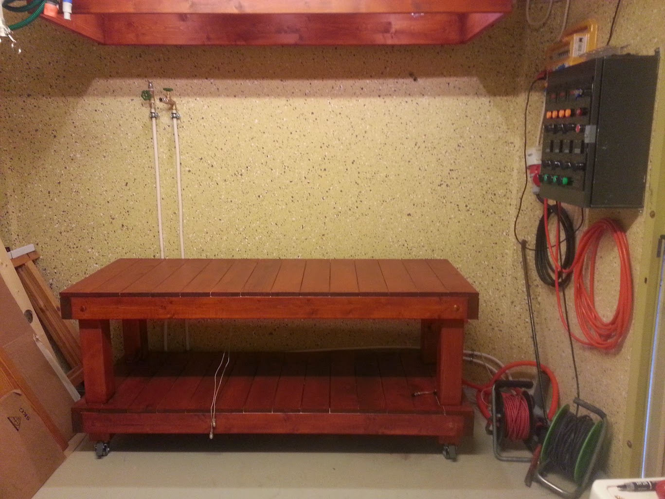
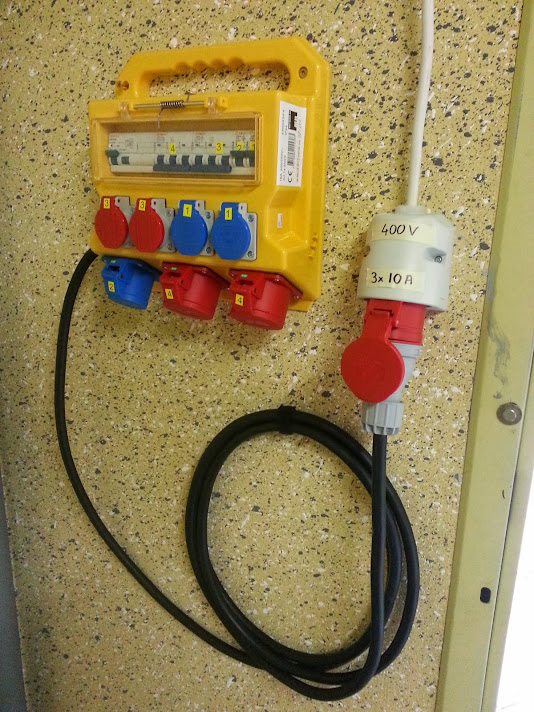
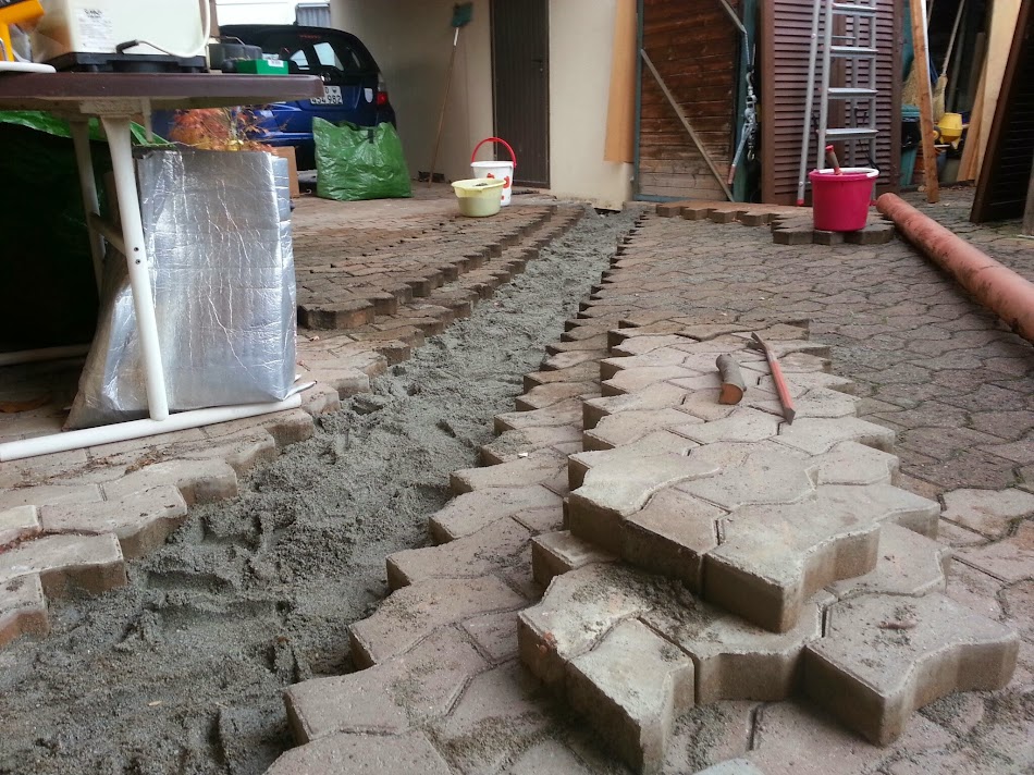
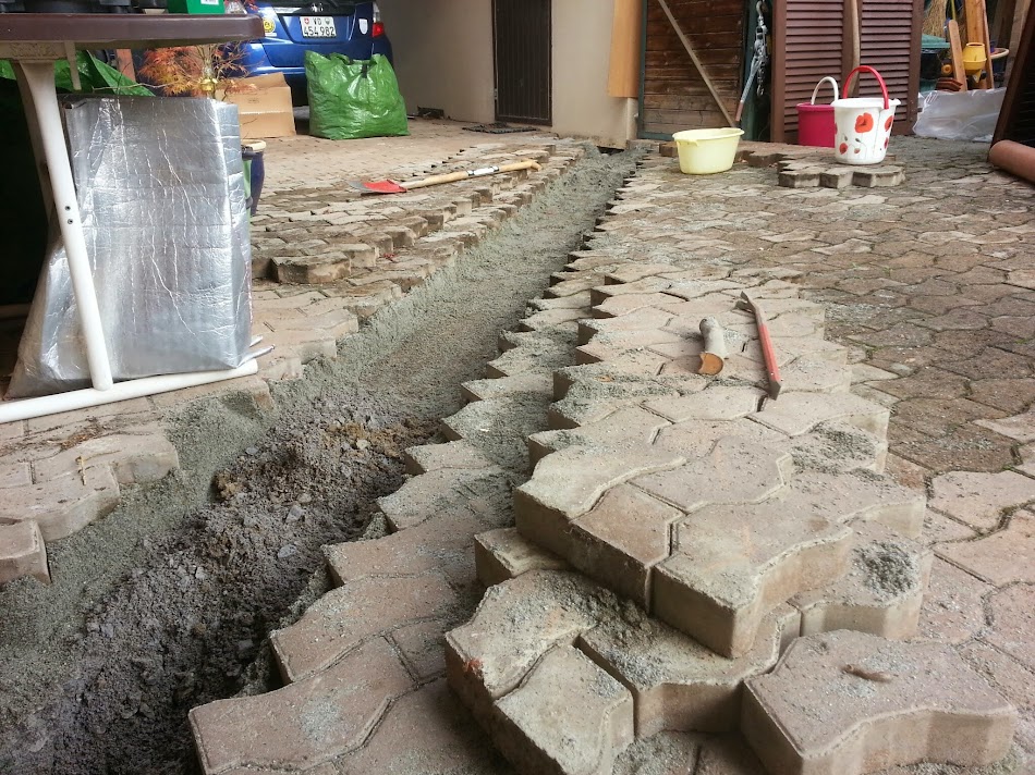
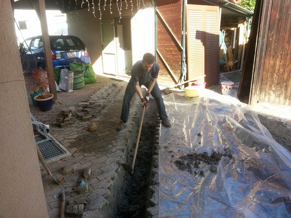
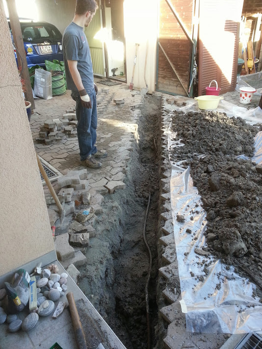
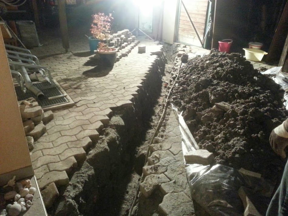
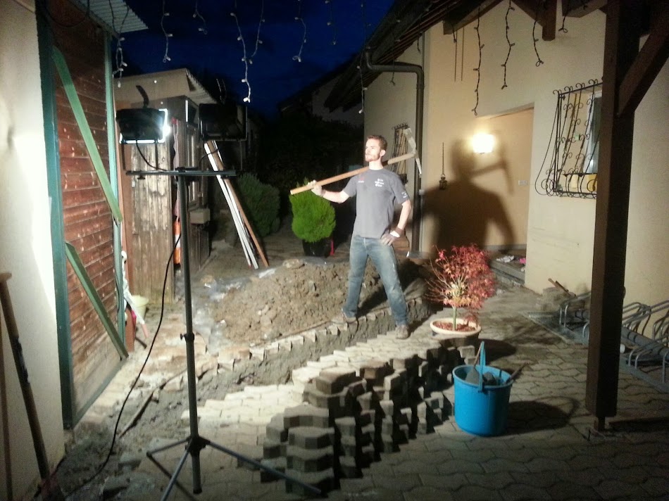
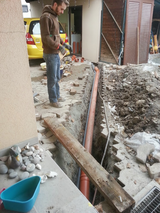
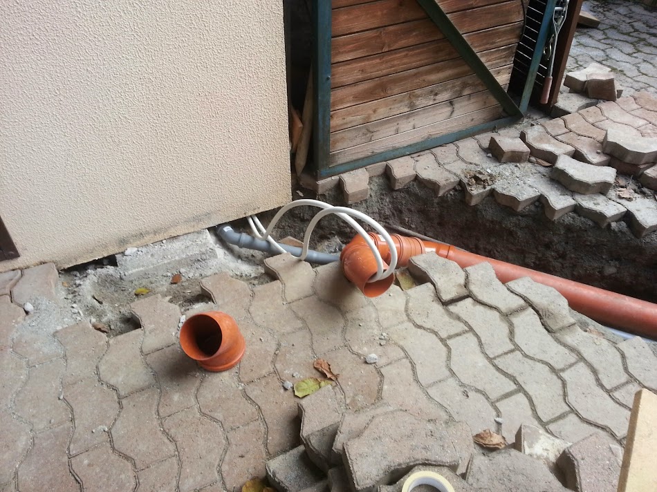
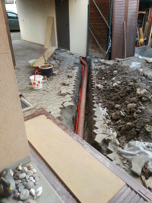
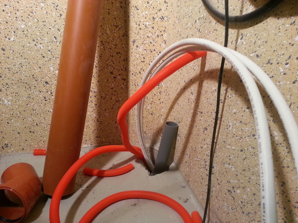
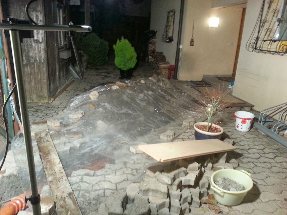
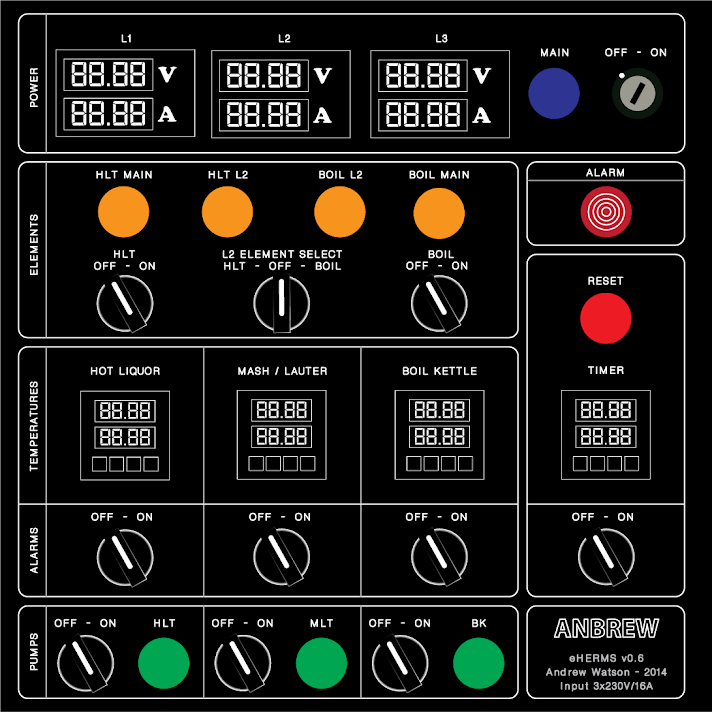
Im now ready to share the progress of my build for a 100% electric setup, for 3x230V 16A, with three 100L kettles (approx 26gal) and three pumps. Ive been working on this for several months now, but I was holding back on sharing until I was certain I had passed the point of no return. After digging a trench from the house to the garage to install water pipes and electrical cables and ordering all the components for my control panel, Im fairly sure Ive now passed that point. Ill probably post pics in chronological order, and at some point this thread should catch up with the actual progress of the build.
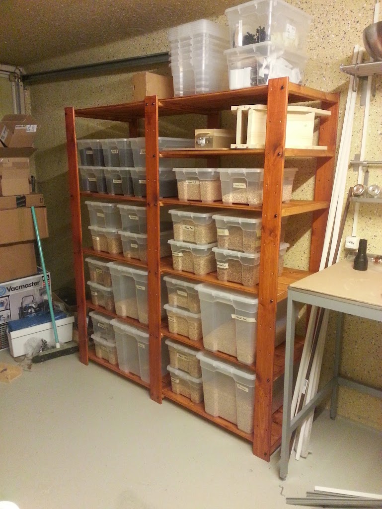
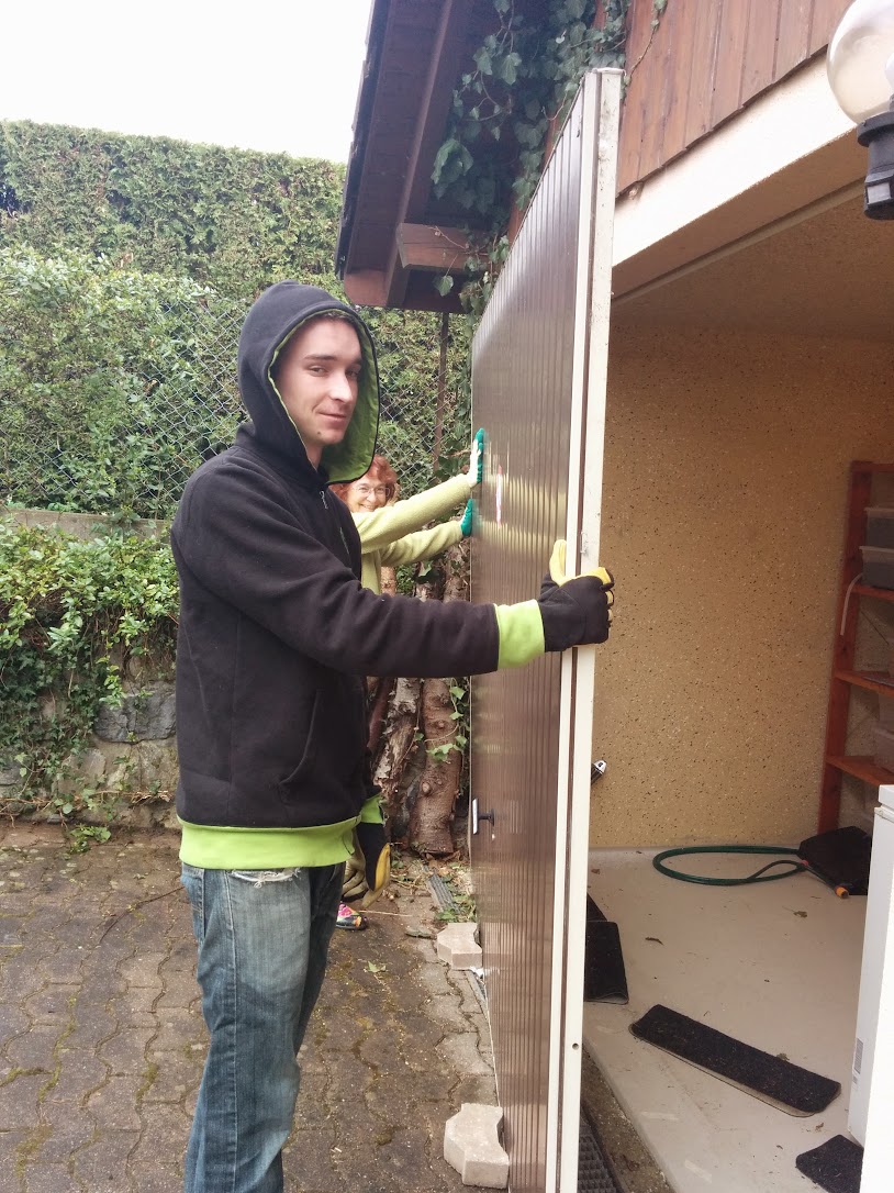
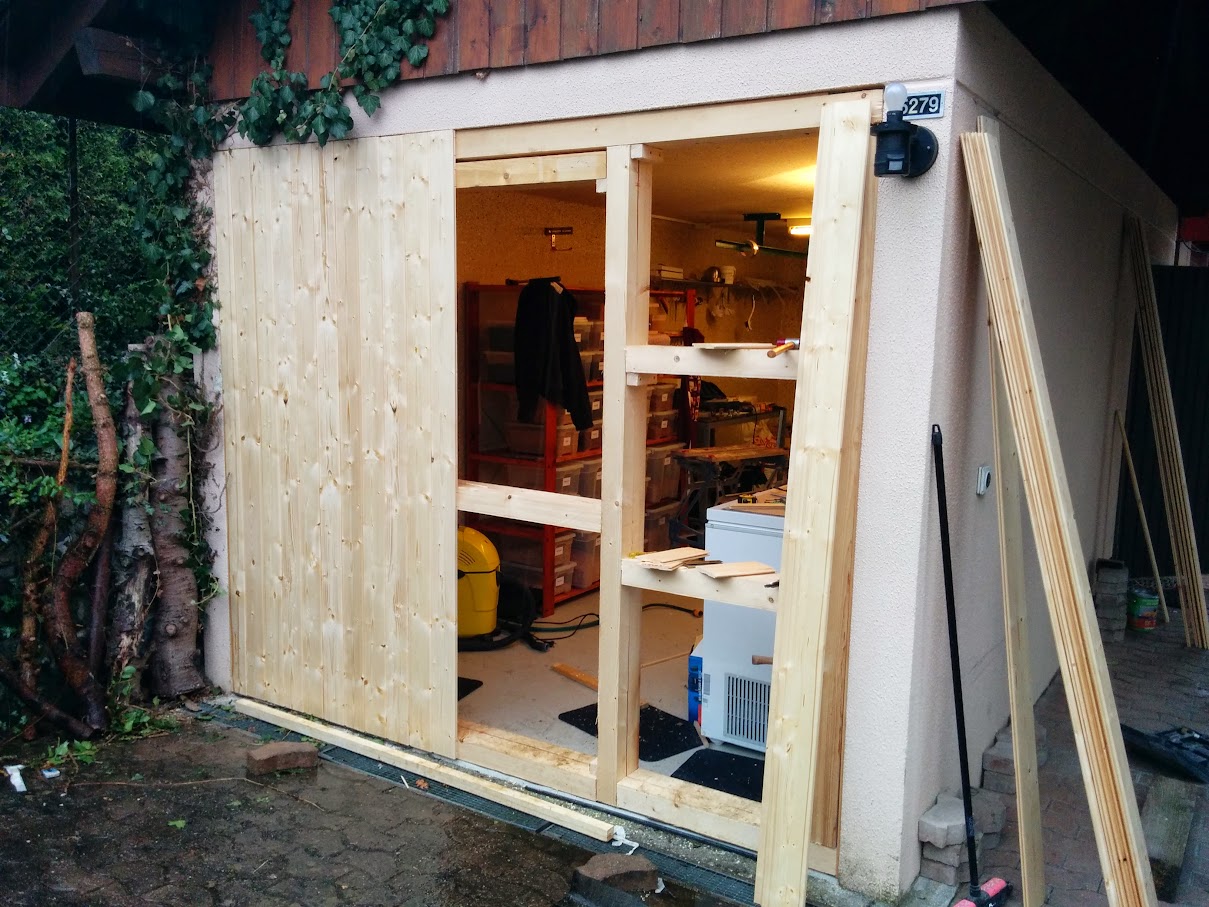
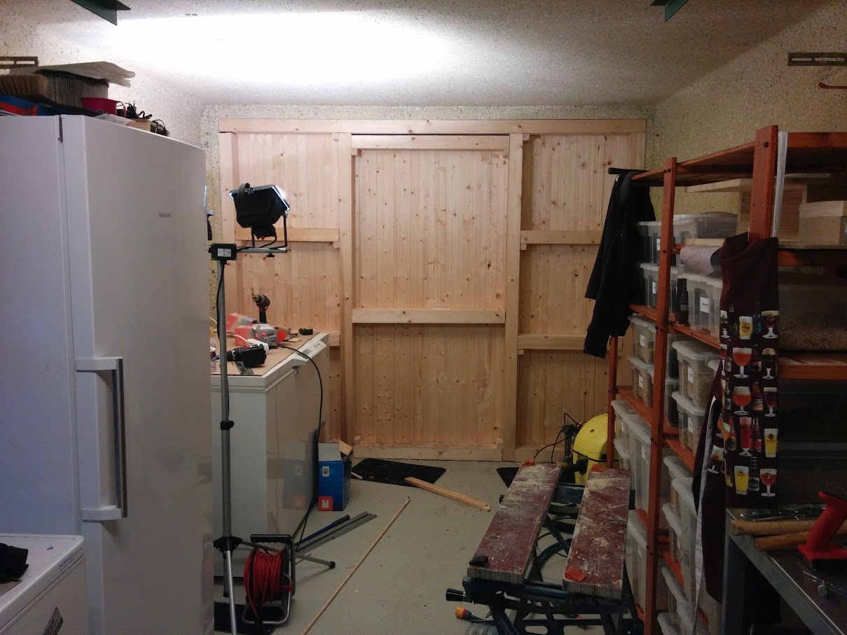
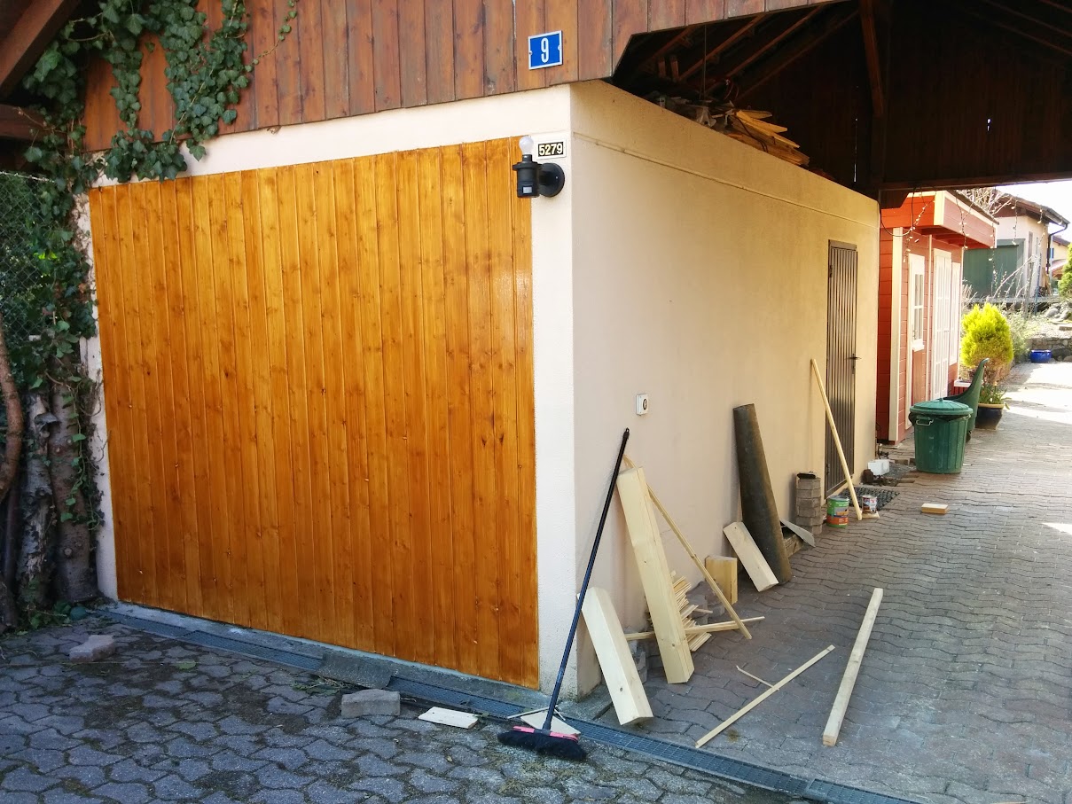
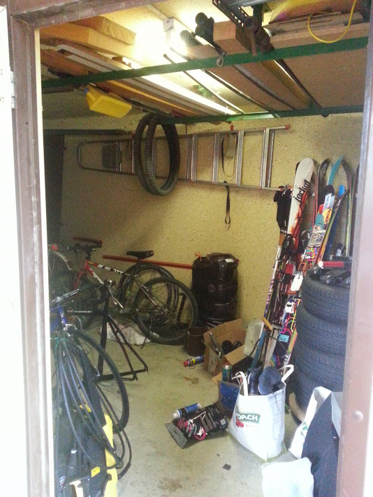
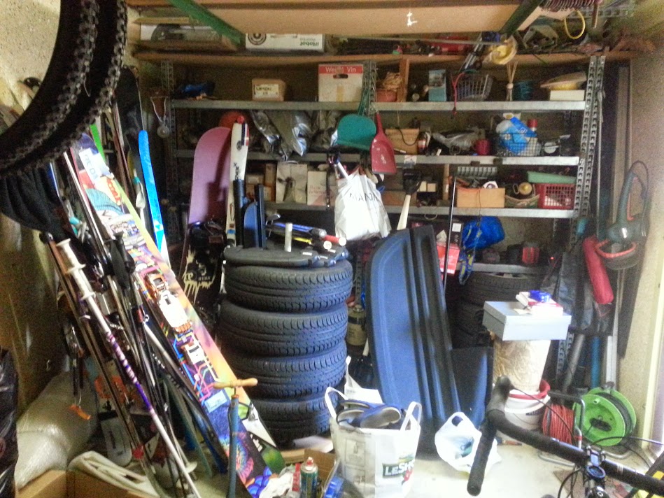
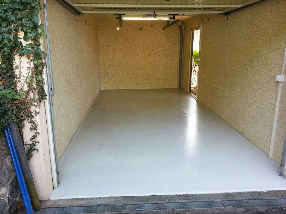
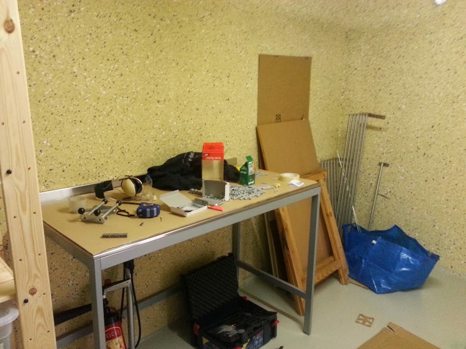
Anyway, it all starts with a... slightly messy garage
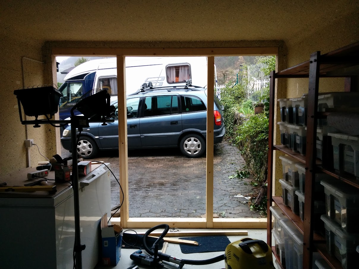
(view from the side door)
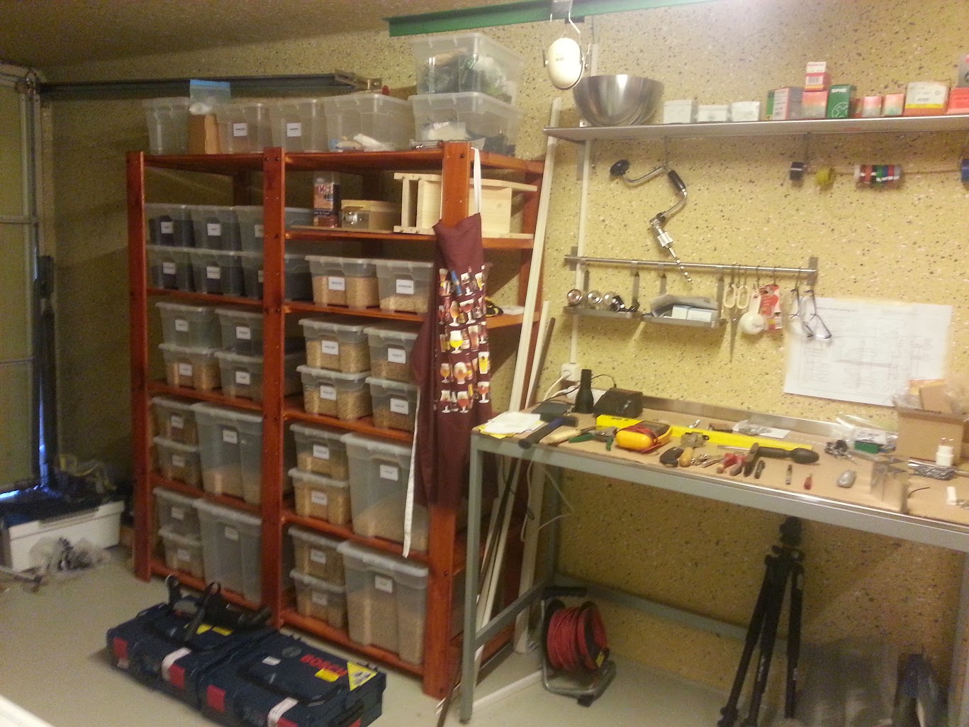
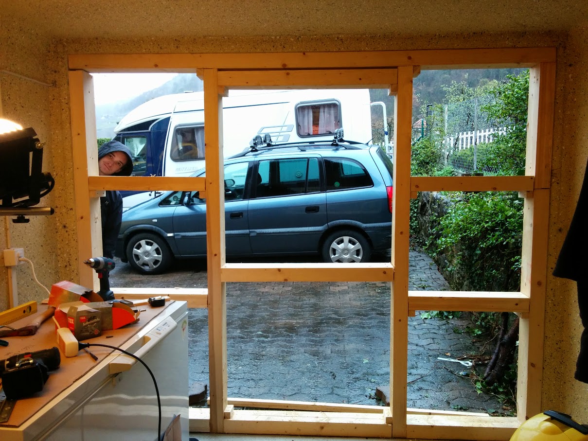
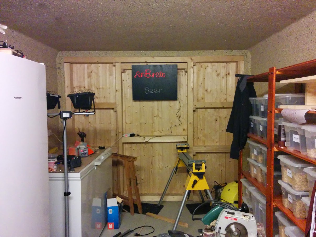
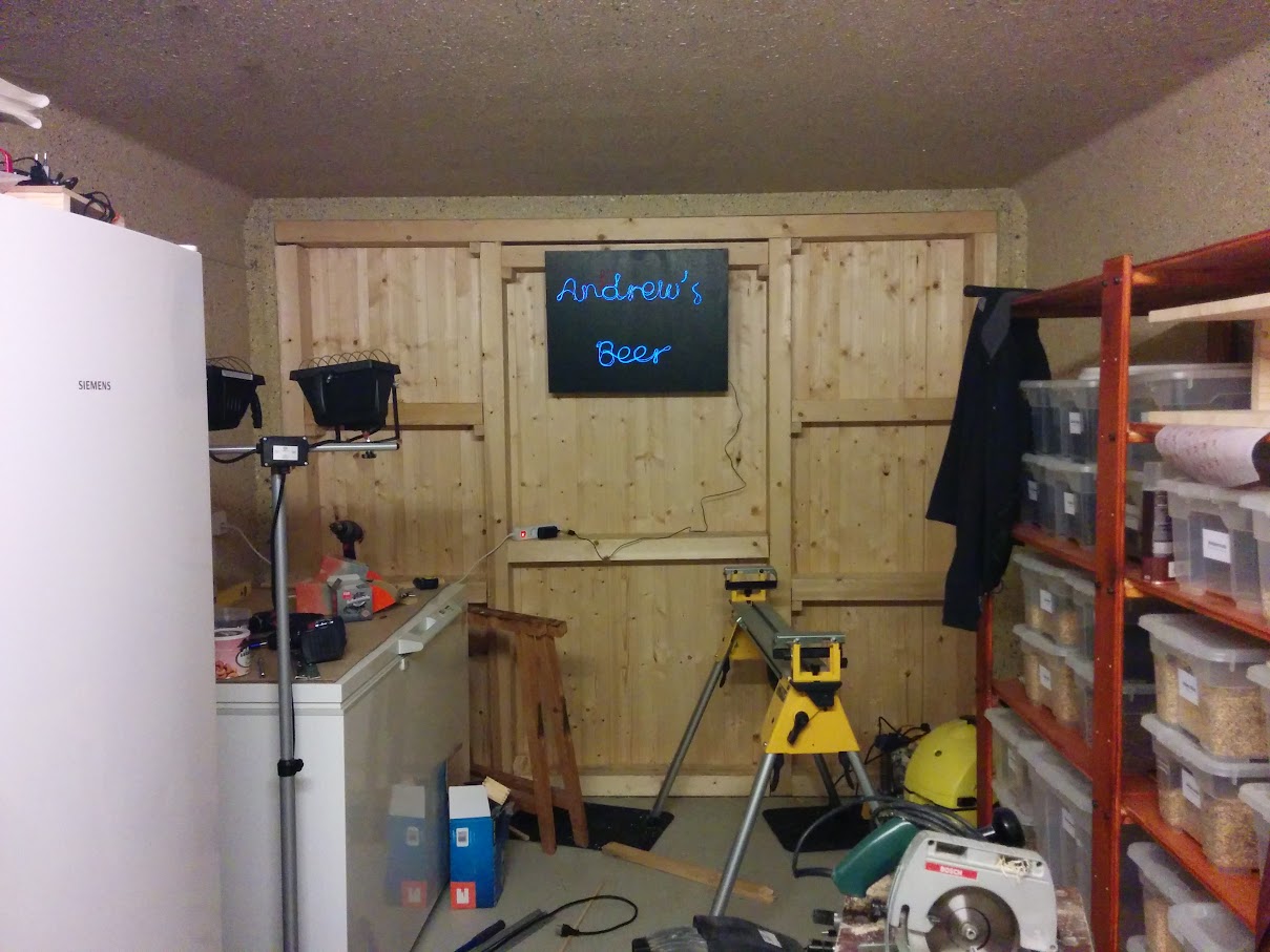
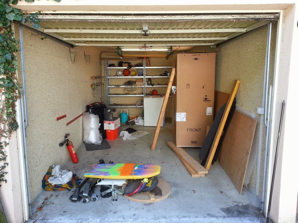
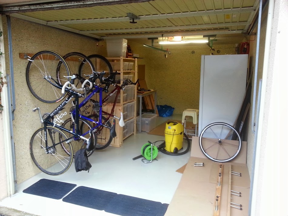
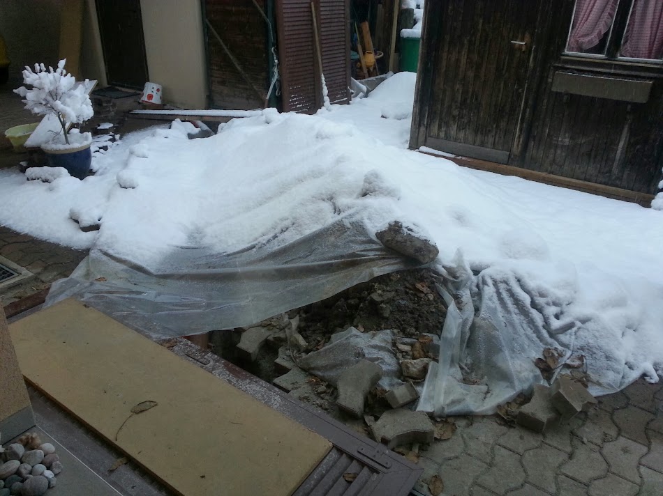
(view from the main door)
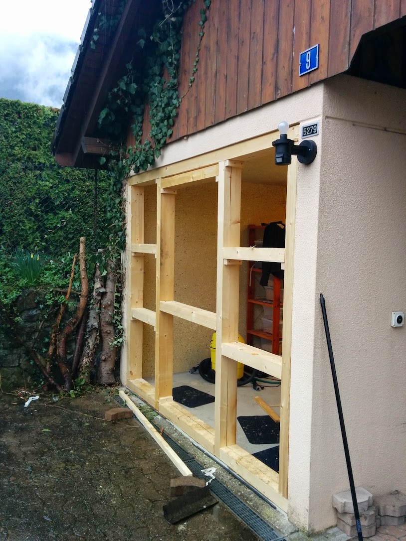
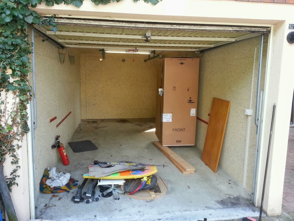
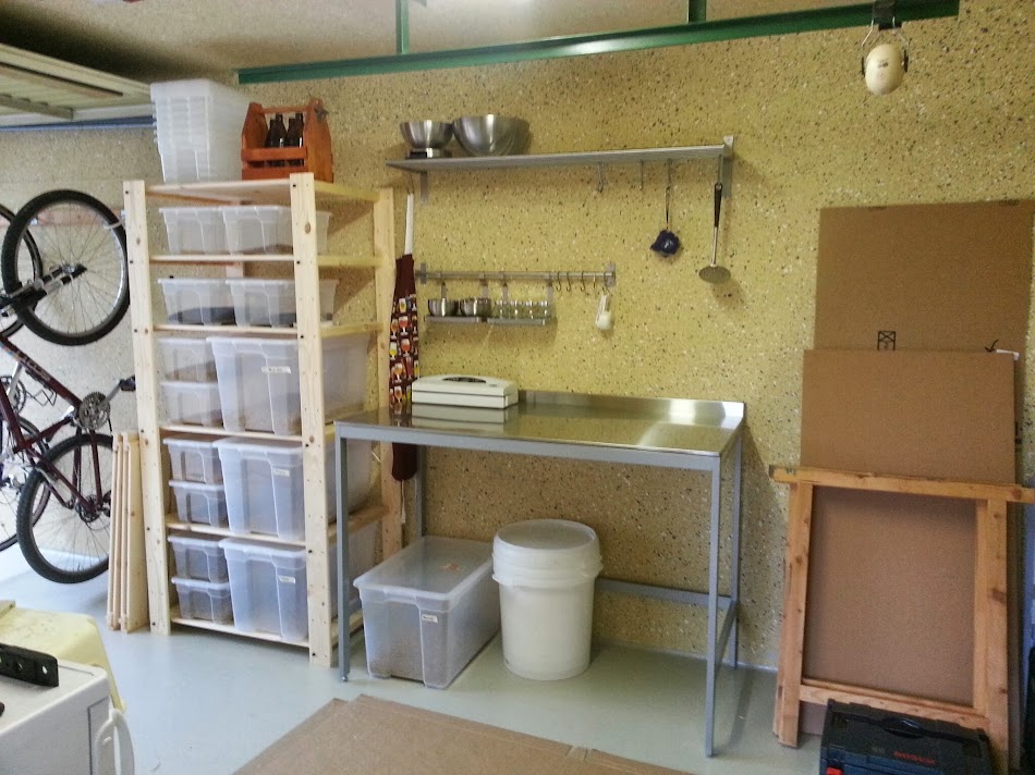
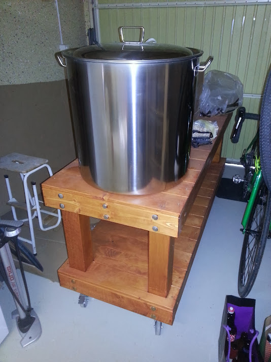
we emptied it:
and then cleaned
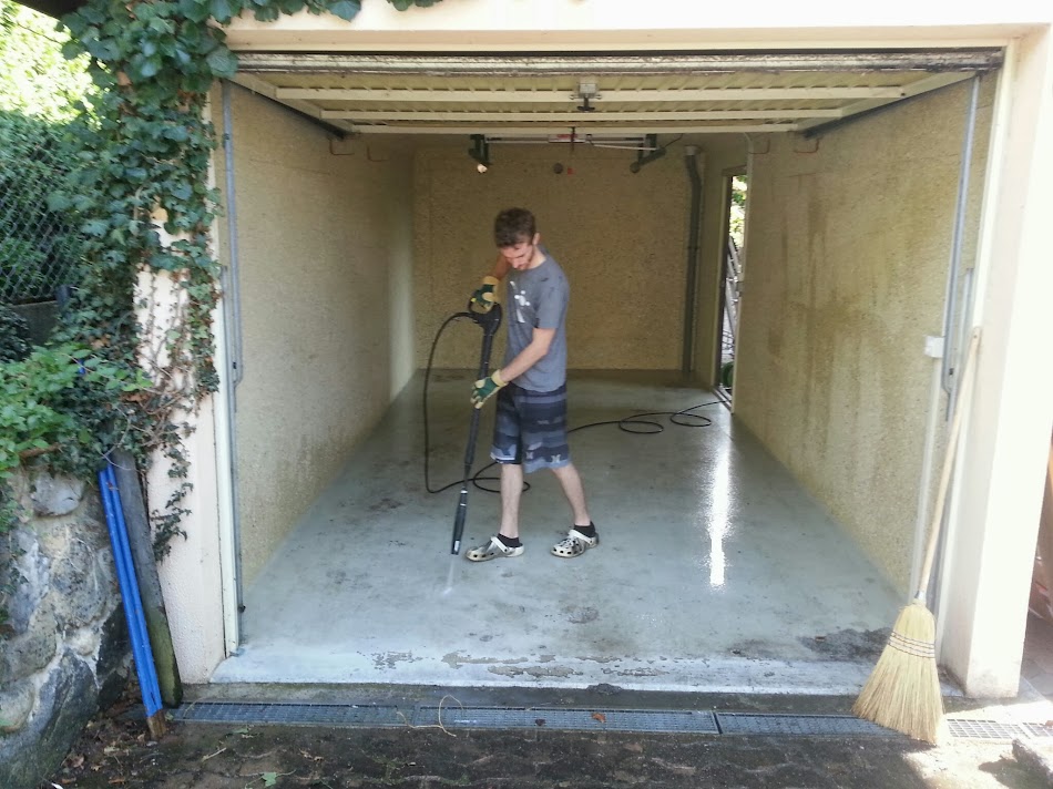
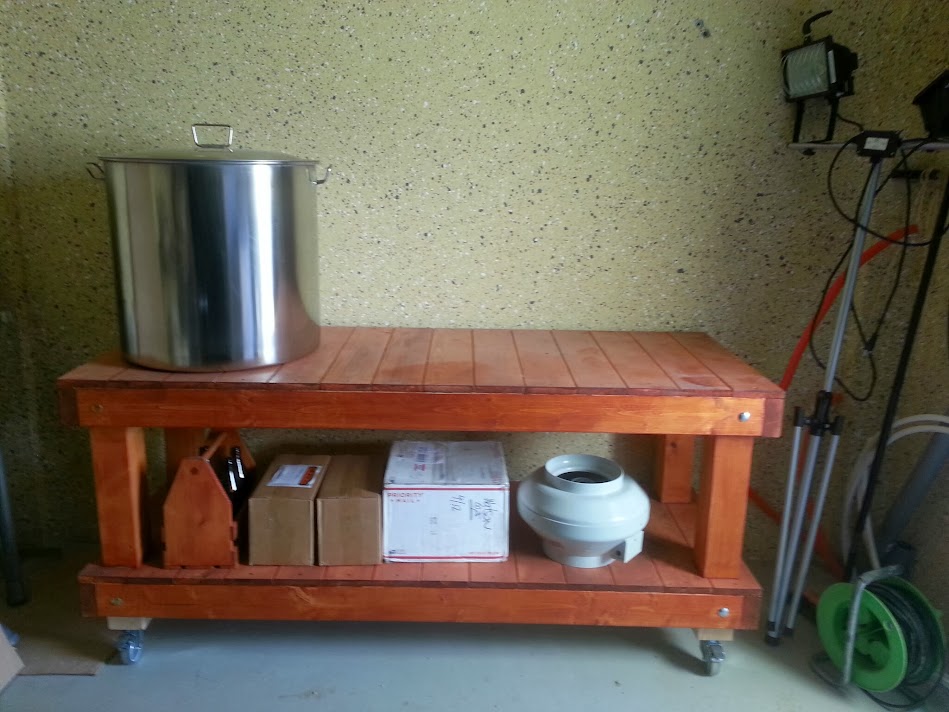
and repainted the floor:
For months Ive been lurking, and drooling over Kals electric brewery instructions. Its taken me a while to wrap my head around how to adapt it to a European power network (here in Switzerland at least, we usually have fairly low amperage, and compensate with three phases at 230V relative to neutral. Ill explain more in detail when I get to the control panel / heating element part)
Im now ready to share the progress of my build for a 100% electric setup, for 3x230V 16A, with three 100L kettles (approx 26gal) and three pumps. Ive been working on this for several months now, but I was holding back on sharing until I was certain I had passed the point of no return. After digging a trench from the house to the garage to install water pipes and electrical cables and ordering all the components for my control panel, Im fairly sure Ive now passed that point. Ill probably post pics in chronological order, and at some point this thread should catch up with the actual progress of the build.
Anyway, it all starts with a... slightly messy garage
(view from the side door)
(view from the main door)
we emptied it:
and then cleaned
and repainted the floor:

 )
)