IndyBlueprints
Well-Known Member
I don't post a lot here, but I've gotten just TONS of great info and knowledge that's helped me take my brewing to the next level.
Background info on me; I've been brewing beer for 23 years, but mostly using low tech / old school methods that have served me well for a long time. I've been making wine since 2009, and have won many international medals and trophies. Although I still ferment about 36-42 gallons of wine a year, My heart is truly into Brewing Beer. Anyways, I FINALLY decided to take my brewing up a few notches. I've been doing some serious DIY projects. The first being I made my own stir plate from scratch, with parts from Radio Shack & the Interwebs. ENded up costing me about $30.00
So, I decided that I wanted to move up to 10 gallon batches instead of 5 gallon, so I would have less work keeping my kegerator full. Once I looked into the details on how to best do that, I decided I needed to tackle some automated brewing. It was really a long process deciding what exactly I wanted to automate. I currently have one Blichmann burner, but plan to get another. My first thought was to set up a couple of PID's and some gas furnace regulators & parts & pieces to have a direct fired gas RIMS system. The more I researched it, and thought about it, the more I leaned towards an electric water heater element fired RIMS.
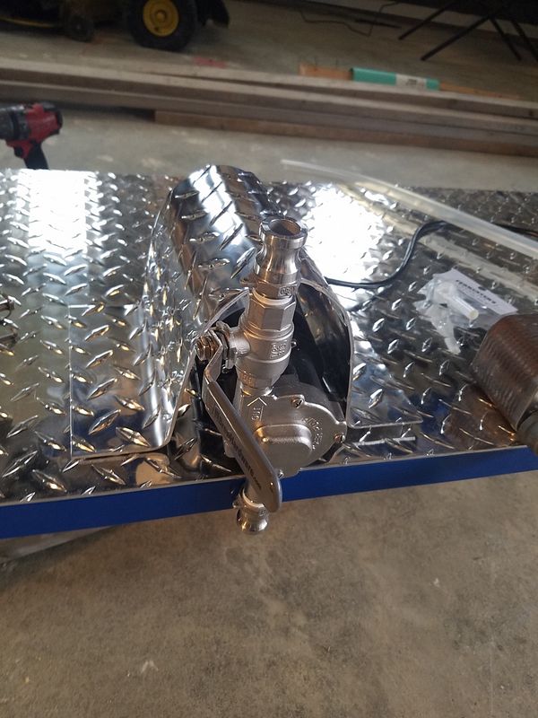
I still am heating my brew kettle & my strike water with gas, but decided to circulate my mash tun with a water heater element. I did look into getting a pre-made RIMS tube, but wanted to save money wherever I could, so I built one out of Stainless pipe & fittings.
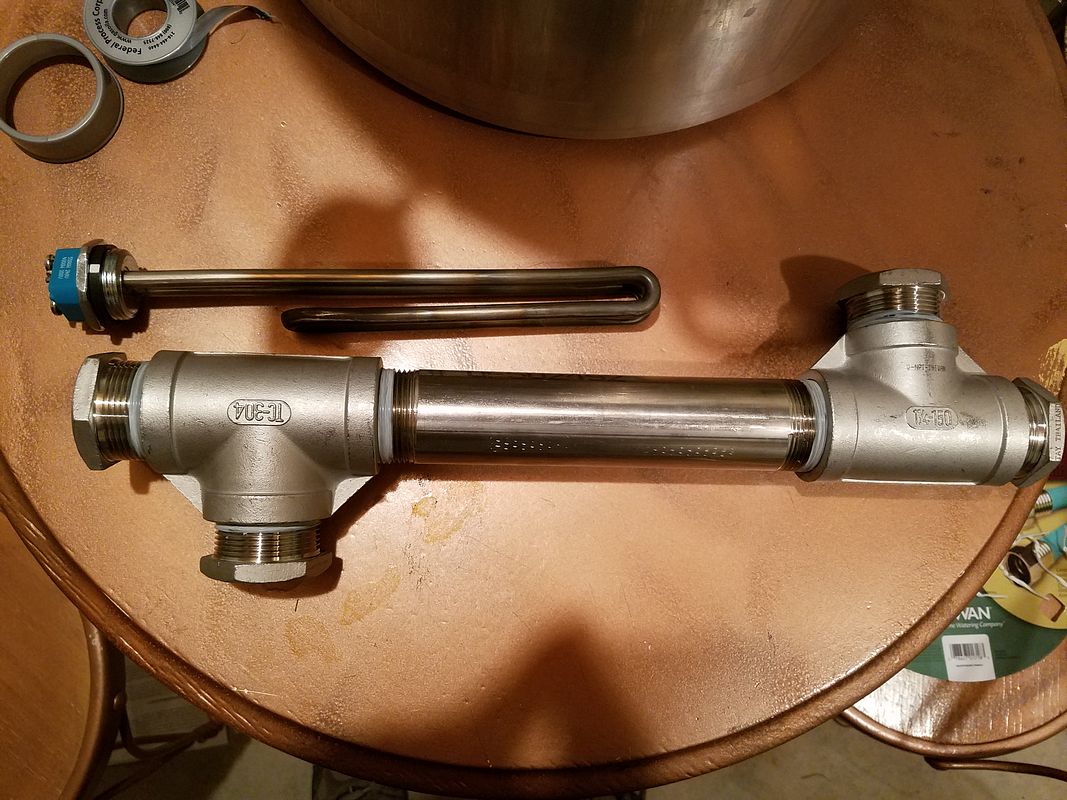
I chose to go with 1-1/4" fittings because I read somewhere that you get the best efficiency & less chance of scorching with smaller pipes. My parts list for this piece is:
(1) 1-1/4" X 8" long pipe nipple.
(2) 1-1/4" T's
(1) 1-1/4" X 1" bushing (for the heater element
(2) 1-1/4" X 1/2" bushings for the Wort in and out. (I'll have quick-connect fittings here)
(1) 1-1/4" X 1/4" bushing for the temperature probe
All of these are 304 Stainless. Total cost about $60.00.
For the heating element, I went with a 5,500W 240V element, that I will wire in 110V, which will produce 1,375W. SHould be enough to quickly raise temperature but not easily scorch it.
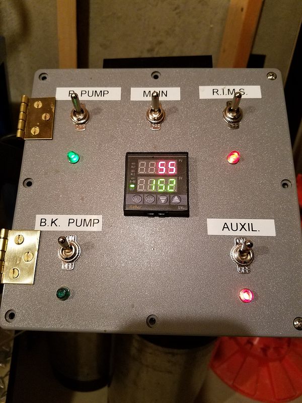
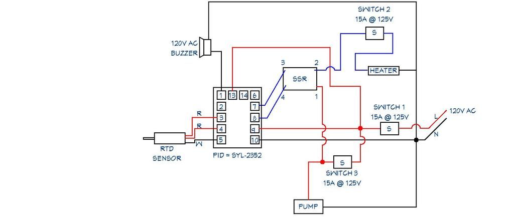
Next were the electronics. I opted to go for just one PID for now, in a box that would also include a couple of switches, one to turn on the circulating pump, and one to turn on the heating element. Additionally, I would have a blue indicator light showing when the pump was on, and a red indicator light showing when the heating element kicked on & off. Options on PID's seem to be unlimited. Unless you are and electrical engineer or know all about these, I highly recommend getting the parts and pieces from a site that will walk you through it. The site I found most highly recommended on here was www.auberins.com. I went on their site and tried to pick out the parts and pieces that I wanted, then clicked on the "Contact Us" button, and asked them if all these parts were compatible. Someone from there quickly emailed me back, and asked me what my project was. When I told her, she told me to change up a few parts, and gave me a couple different options, as she was quite familiar with a RIMS System. Here are the parts I got:
1 ea. External Mount Heat Sink for 25A SSR Item #: HS25ET
1 ea. Liquid tight RTD sensor, 2 in, 1/4 NPT Thread Item #: PT100-L50NPT
3 ea. 3-PIN SPDT ON/ON Toggle Switch, Buzzer Mute Item #: TS1
1 ea. Compact LED Indicator, 120V AC Item #: IND-2 LED Color Option -Red
1 ea. Compact LED Indicator, 120V AC Item #: IND-2 LED Color Option - Blue
1 ea. 1/16 DIN PID Temperature Controller (For SSR) Item #: SYL-2352
1 ea. 25A SSR Item #: MGR-1D4825
Total with shipping was $120.84.
For a box, I went to "big-box" store and got an 8" X 8" grey plastic electrical connection box for about $14.00.
Next up: Brew Stand.
So, after countless hours of "research", I came up with a design for a single tier brew stand to perfectly fit a couple of Blichmann burners. No, it's not an original design, as it looks remarkably similar to countless others, based on the Brutus 10. But this one's mine! Here's the plans:

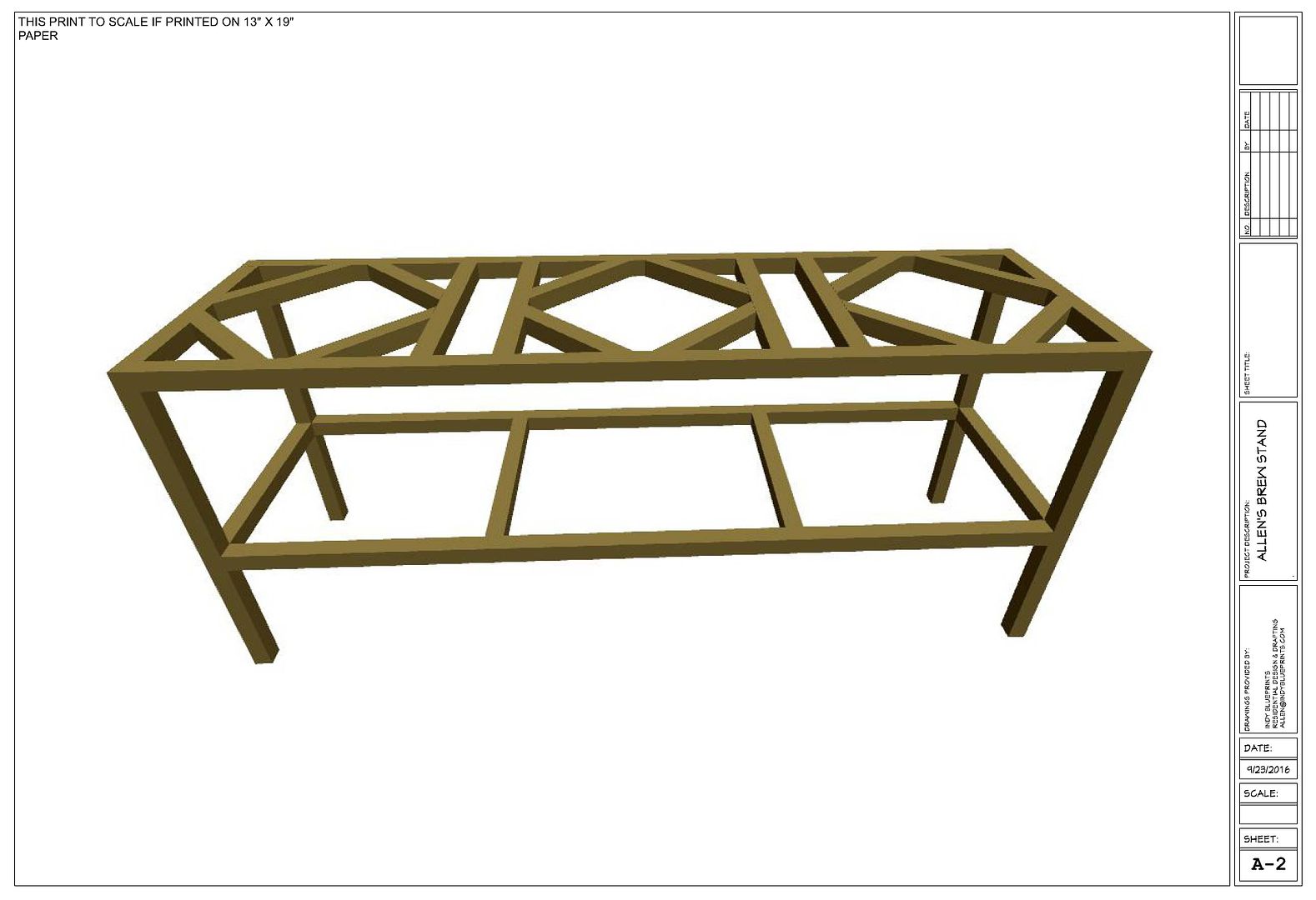
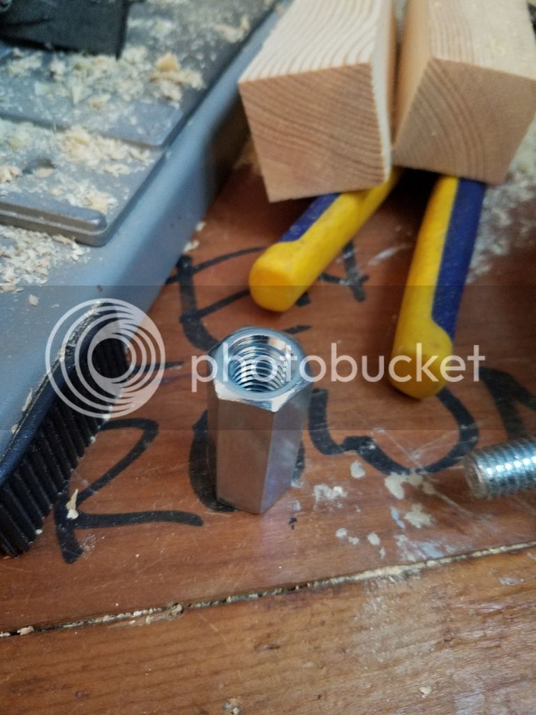
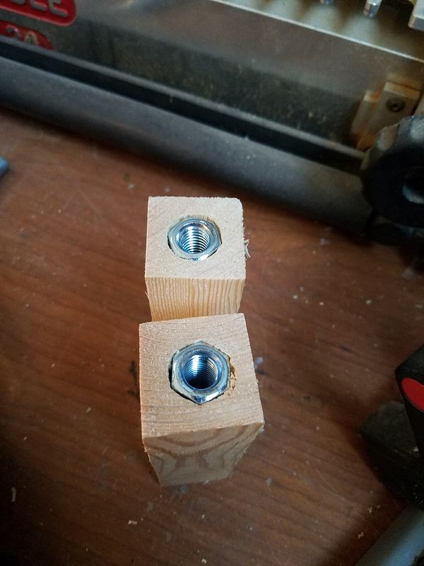
The reason I made the dimensions exactly what they are is to fit the Blichmann burners. The legs on the burners are 17-1/4" outside to outside, so I made the dimensions on the inside of the squares 17-1/2", so I would have a little bit of play. The burners will mount by drilling a hole through the stand on all 4 sides, and through bolting through the legs. I plan on mounting the top of the burner assembly even with the top of the stand. I will invert the metal supports on the burner so the leg that sticks up, stick down, but it can still hold a smaller pot if necessary.
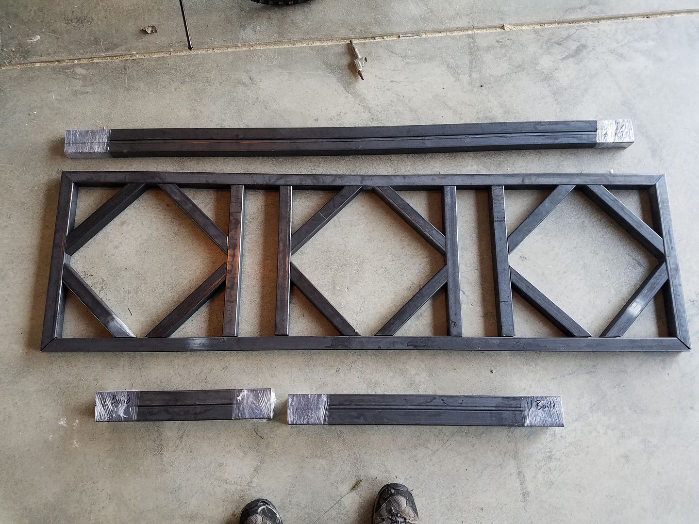
I couldn't afford Stainless, so I went with 1-1/2" square tube cold steel. I found a supplier here in Indy called The Metal Supermarket, that is just awesome. I gave them my design and they cut all the pieces to size, for about $160.00. Here's the upper section assembled on the floor before welding:
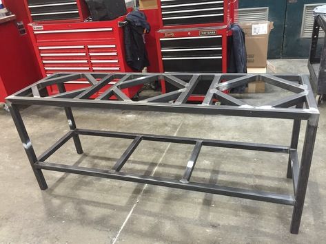
The good news is I got a buddy of mine to weld it up for some trade labor on some blueprints drawn for an upcoming project of his. Here's the welded up product:
The next piece of the puzzle was how to paint it. I looked at getting it powder coated, ceramic coated, painted black with high-temp engine paint, etc. I knew powder coating would look the best, but I was concerned that the direct heat from the burners could possibly discolor or damage the powder coating. After wrestling it around in my head for a while, I decided I didn't care. Living in the "Racing Capitol Of The World" (Indy), we have plenty of shops near that do powder coating. I priced it out to 6 different shops, and the best price I got was $160.00 to sand blast & powder coat. The good news is, I know some people in the business, so again I was able to trade out & get it done with the barter system! I'm pretty sure I am going to go with Colt's Blue. It's not powder coated yet, because I need to completely assemble the system, making sure I have all the hole drilled and tapped to mount everything before it's coated. The reason being that if you try to drill after its powder coated, you will chip the powder & it will look bad.
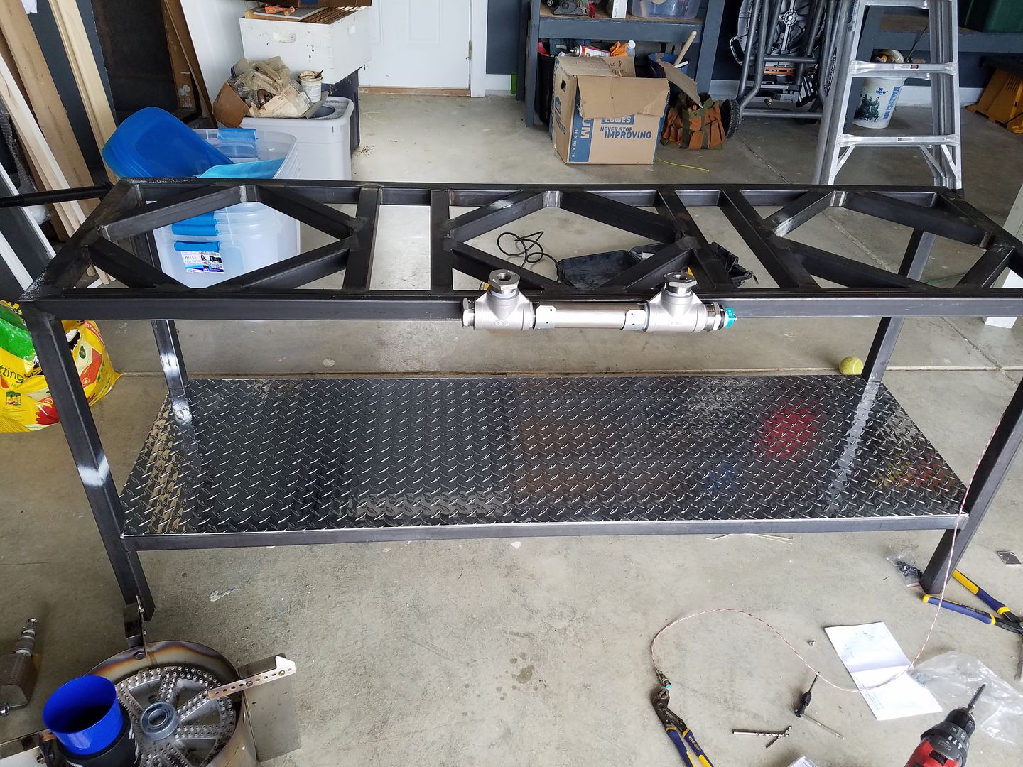
My next thought was, if I'm going to do it, I might as well do it right, and make it look BaddA$$! Of course Powder Coating wasn't enough, so I got a 20-1/2" X 69-1/2" piece of Diamond Plate for the lower level for another $60.00.
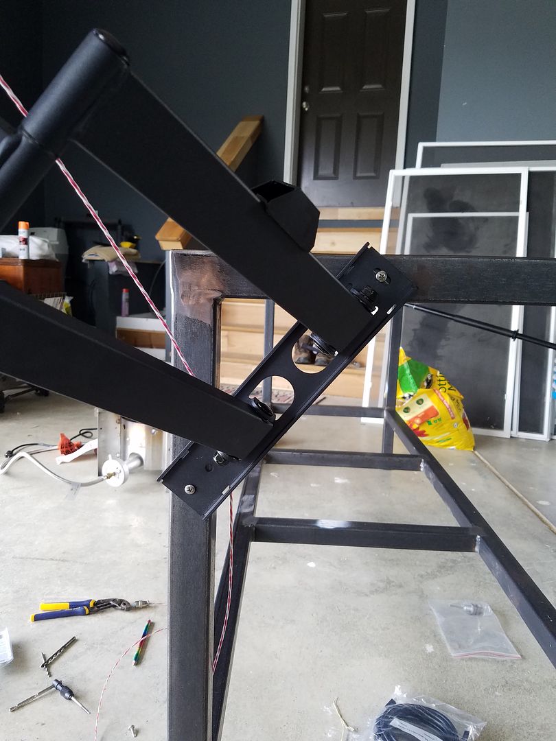
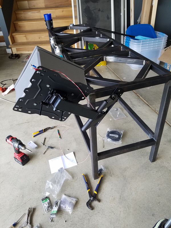
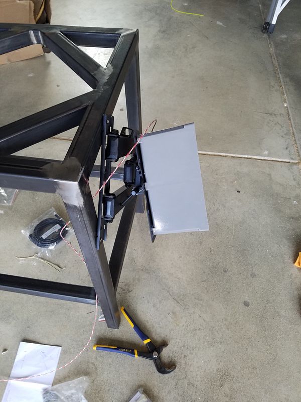
To mount the box of electronics, I went inexpensive but functional and bought a "full motion" TV wall mount from Wally World. They didn't have many choices in the store, so I got mine online for $24.98. Make sure you get one that has a small vertical part that mounts to the stand, as opposed to one that has a larger square part that mounts to the wall. Here's a few shots of the box on the stand:
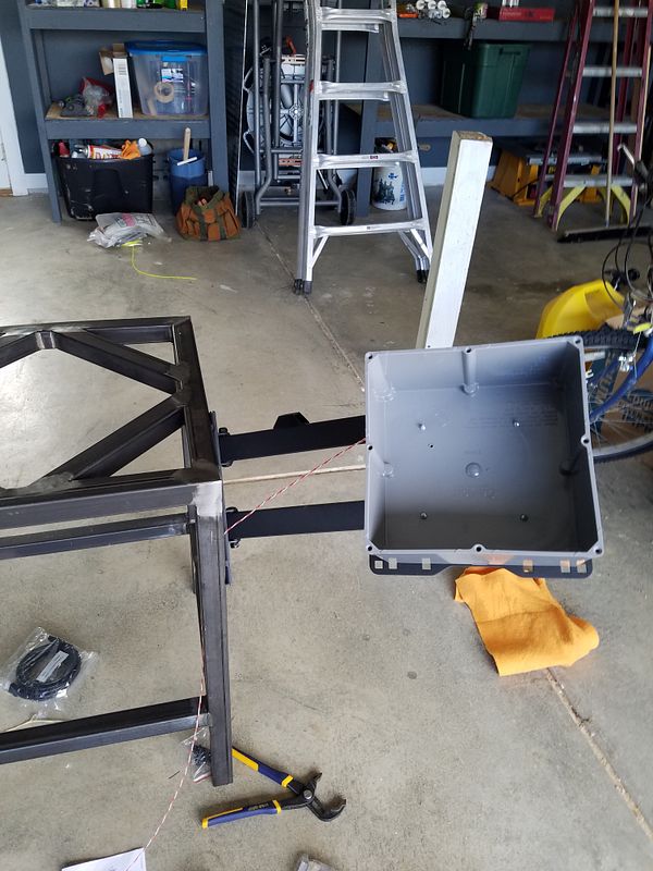
The best part it that it tucks away tight when I'm not using it:
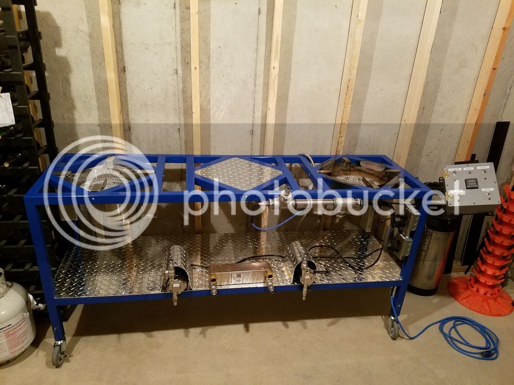
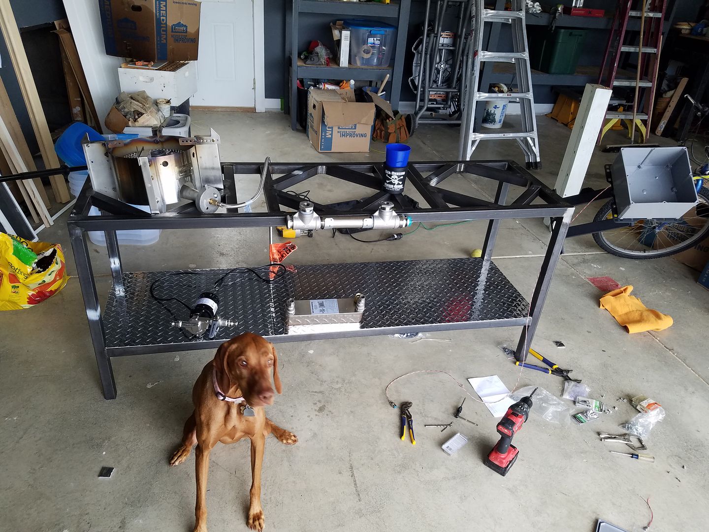
Here's the last image for today. My thought is to mount the RIMS Tube front and center on the upper level, the Plate Chiller (from Duda Diesel) front and center on lower level, one pump right and one pump left on lower level, with another smaller piece of diamond plate bent over each of the pumps to protect from overflows.
See any issues with this setup? Have any suggested changes? I'll of course post additional details as I progress!
Background info on me; I've been brewing beer for 23 years, but mostly using low tech / old school methods that have served me well for a long time. I've been making wine since 2009, and have won many international medals and trophies. Although I still ferment about 36-42 gallons of wine a year, My heart is truly into Brewing Beer. Anyways, I FINALLY decided to take my brewing up a few notches. I've been doing some serious DIY projects. The first being I made my own stir plate from scratch, with parts from Radio Shack & the Interwebs. ENded up costing me about $30.00
So, I decided that I wanted to move up to 10 gallon batches instead of 5 gallon, so I would have less work keeping my kegerator full. Once I looked into the details on how to best do that, I decided I needed to tackle some automated brewing. It was really a long process deciding what exactly I wanted to automate. I currently have one Blichmann burner, but plan to get another. My first thought was to set up a couple of PID's and some gas furnace regulators & parts & pieces to have a direct fired gas RIMS system. The more I researched it, and thought about it, the more I leaned towards an electric water heater element fired RIMS.
I still am heating my brew kettle & my strike water with gas, but decided to circulate my mash tun with a water heater element. I did look into getting a pre-made RIMS tube, but wanted to save money wherever I could, so I built one out of Stainless pipe & fittings.
I chose to go with 1-1/4" fittings because I read somewhere that you get the best efficiency & less chance of scorching with smaller pipes. My parts list for this piece is:
(1) 1-1/4" X 8" long pipe nipple.
(2) 1-1/4" T's
(1) 1-1/4" X 1" bushing (for the heater element
(2) 1-1/4" X 1/2" bushings for the Wort in and out. (I'll have quick-connect fittings here)
(1) 1-1/4" X 1/4" bushing for the temperature probe
All of these are 304 Stainless. Total cost about $60.00.
For the heating element, I went with a 5,500W 240V element, that I will wire in 110V, which will produce 1,375W. SHould be enough to quickly raise temperature but not easily scorch it.
Next were the electronics. I opted to go for just one PID for now, in a box that would also include a couple of switches, one to turn on the circulating pump, and one to turn on the heating element. Additionally, I would have a blue indicator light showing when the pump was on, and a red indicator light showing when the heating element kicked on & off. Options on PID's seem to be unlimited. Unless you are and electrical engineer or know all about these, I highly recommend getting the parts and pieces from a site that will walk you through it. The site I found most highly recommended on here was www.auberins.com. I went on their site and tried to pick out the parts and pieces that I wanted, then clicked on the "Contact Us" button, and asked them if all these parts were compatible. Someone from there quickly emailed me back, and asked me what my project was. When I told her, she told me to change up a few parts, and gave me a couple different options, as she was quite familiar with a RIMS System. Here are the parts I got:
1 ea. External Mount Heat Sink for 25A SSR Item #: HS25ET
1 ea. Liquid tight RTD sensor, 2 in, 1/4 NPT Thread Item #: PT100-L50NPT
3 ea. 3-PIN SPDT ON/ON Toggle Switch, Buzzer Mute Item #: TS1
1 ea. Compact LED Indicator, 120V AC Item #: IND-2 LED Color Option -Red
1 ea. Compact LED Indicator, 120V AC Item #: IND-2 LED Color Option - Blue
1 ea. 1/16 DIN PID Temperature Controller (For SSR) Item #: SYL-2352
1 ea. 25A SSR Item #: MGR-1D4825
Total with shipping was $120.84.
For a box, I went to "big-box" store and got an 8" X 8" grey plastic electrical connection box for about $14.00.
Next up: Brew Stand.
So, after countless hours of "research", I came up with a design for a single tier brew stand to perfectly fit a couple of Blichmann burners. No, it's not an original design, as it looks remarkably similar to countless others, based on the Brutus 10. But this one's mine! Here's the plans:
The reason I made the dimensions exactly what they are is to fit the Blichmann burners. The legs on the burners are 17-1/4" outside to outside, so I made the dimensions on the inside of the squares 17-1/2", so I would have a little bit of play. The burners will mount by drilling a hole through the stand on all 4 sides, and through bolting through the legs. I plan on mounting the top of the burner assembly even with the top of the stand. I will invert the metal supports on the burner so the leg that sticks up, stick down, but it can still hold a smaller pot if necessary.
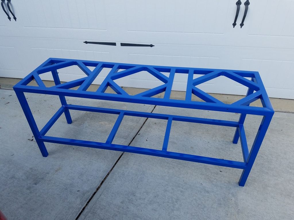
I couldn't afford Stainless, so I went with 1-1/2" square tube cold steel. I found a supplier here in Indy called The Metal Supermarket, that is just awesome. I gave them my design and they cut all the pieces to size, for about $160.00. Here's the upper section assembled on the floor before welding:
The good news is I got a buddy of mine to weld it up for some trade labor on some blueprints drawn for an upcoming project of his. Here's the welded up product:
The next piece of the puzzle was how to paint it. I looked at getting it powder coated, ceramic coated, painted black with high-temp engine paint, etc. I knew powder coating would look the best, but I was concerned that the direct heat from the burners could possibly discolor or damage the powder coating. After wrestling it around in my head for a while, I decided I didn't care. Living in the "Racing Capitol Of The World" (Indy), we have plenty of shops near that do powder coating. I priced it out to 6 different shops, and the best price I got was $160.00 to sand blast & powder coat. The good news is, I know some people in the business, so again I was able to trade out & get it done with the barter system! I'm pretty sure I am going to go with Colt's Blue. It's not powder coated yet, because I need to completely assemble the system, making sure I have all the hole drilled and tapped to mount everything before it's coated. The reason being that if you try to drill after its powder coated, you will chip the powder & it will look bad.
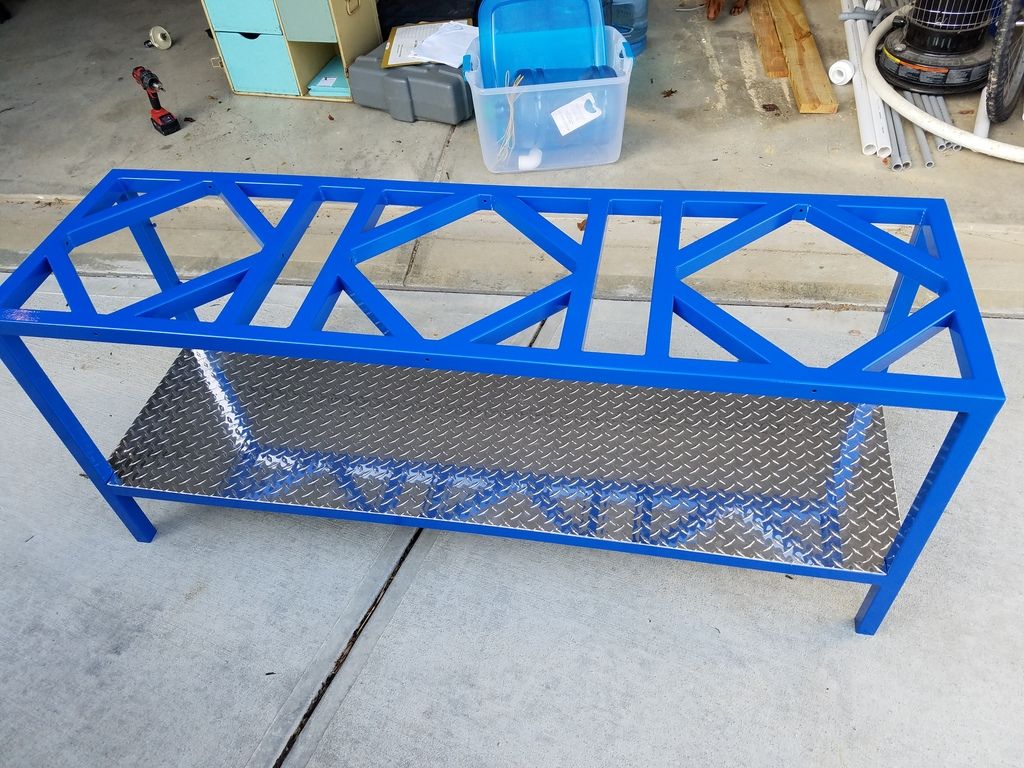
My next thought was, if I'm going to do it, I might as well do it right, and make it look BaddA$$! Of course Powder Coating wasn't enough, so I got a 20-1/2" X 69-1/2" piece of Diamond Plate for the lower level for another $60.00.
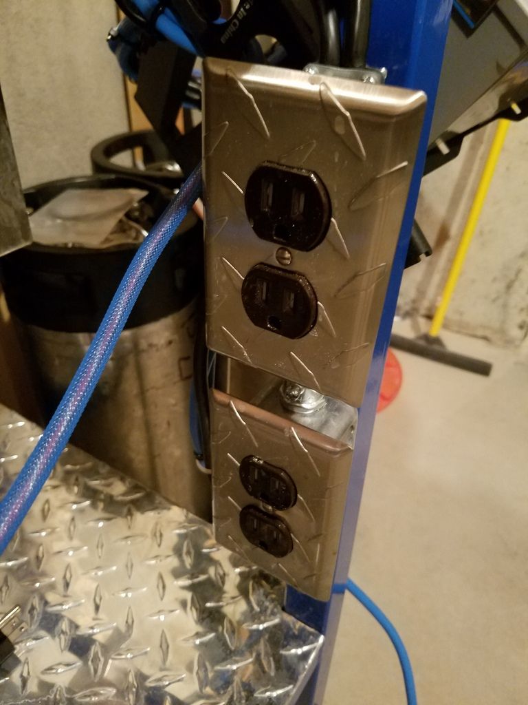
To mount the box of electronics, I went inexpensive but functional and bought a "full motion" TV wall mount from Wally World. They didn't have many choices in the store, so I got mine online for $24.98. Make sure you get one that has a small vertical part that mounts to the stand, as opposed to one that has a larger square part that mounts to the wall. Here's a few shots of the box on the stand:
The best part it that it tucks away tight when I'm not using it:
Here's the last image for today. My thought is to mount the RIMS Tube front and center on the upper level, the Plate Chiller (from Duda Diesel) front and center on lower level, one pump right and one pump left on lower level, with another smaller piece of diamond plate bent over each of the pumps to protect from overflows.
See any issues with this setup? Have any suggested changes? I'll of course post additional details as I progress!