A Brewpi Remix Build

Homebrew Talk - Beer, Wine, Mead, & Cider Brewing Discussion Forum

Help Support Homebrew Talk - Beer, Wine, Mead, & Cider Brewing Discussion Forum:

This site may earn a commission from merchant affiliate links, including eBay, Amazon, and others.

OkieNotFromMuskogee

Active Member
Joined
Mar 8, 2020
Messages
32
Reaction score
20
Location
Tulsa
Current Progress (will update as I go)
Ready for it's first batch!

Overview
I'm a bit new to microcontrollers and Raspberry Pi's so I wanted to post a build log that contains useful links, some issues I ran into, and resolutions. Hopefully it will help someone else, and be a reference for myself if I run into these issues again at some point.

Huge thank you to @LBussy for brewpi remix, and for the excellent documentation. Also the original creators of brewpi for making and keeping it open source. Check out their store http://www.brewpi.com

Goals
  • Use 1st gen Raspberry Pi rev B I had laying around
  • Use power supply to power Raspberry Pi so only one plug/power cord is needed
  • Use RJ45 connectors for the temp sensors since I already had connectors, keystones, and CAT5 cable laying around
  • Initiate shutdown via button (LBussy's suggestion when running headless)
  • No LCD display, possible OLED or eInk at a later time
Resources

Parts
Wiring
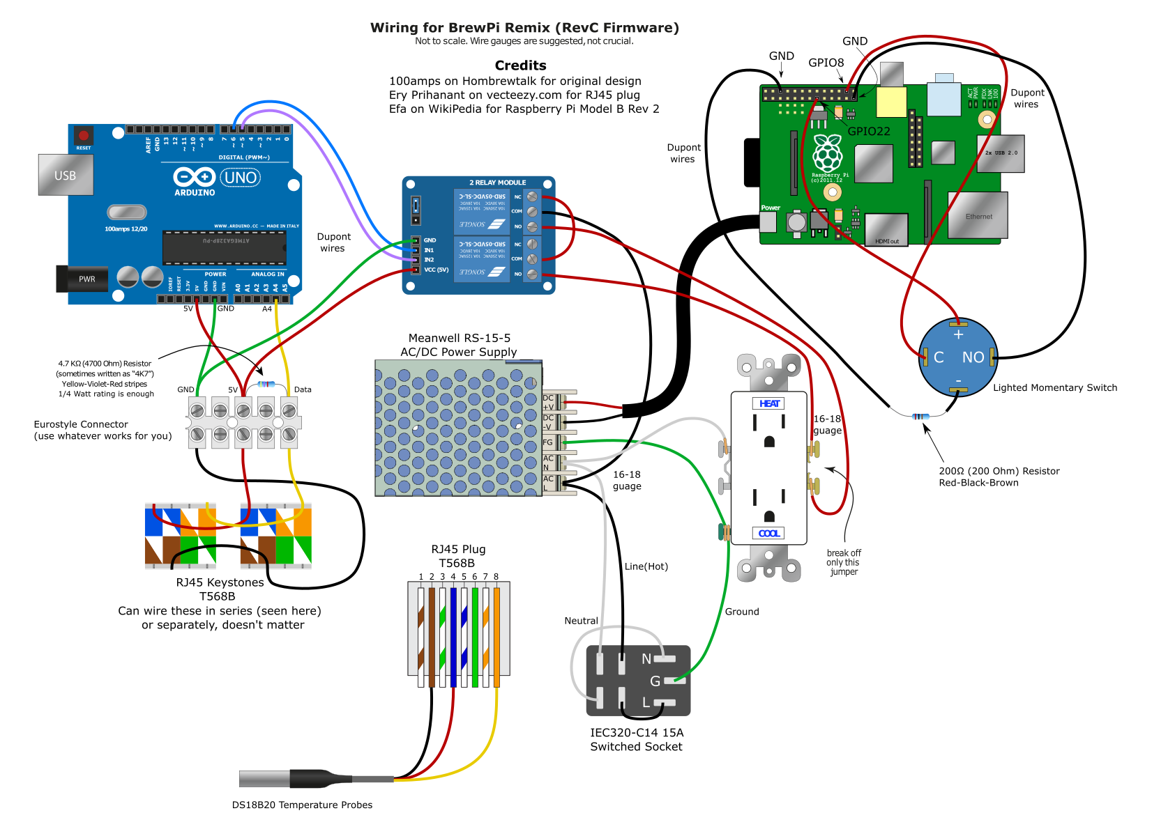
Below is an illustration of my wiring. A big thanks to @100amps for being kind enough to share some of the work he's done so I could use it. I will make one clarification on powering the Raspberry Pi from the AC/DC power supply. I chose to cut a USB cable and strip the wires down, and pwered it that way, as opposed to using the GPIO pins. I did this so the RPI is protected from over voltage and current spikes. Now with the power supply I used I don't belive that would be an issue, but I'd rather not have to yank out the RPI and replace it.

Okie-BrewPI-Remix.png


Approach
Test everything as you go, and take a break if you need to. This will save you time and headaches later, trust me. Things to test include:
  • Testing all electrical connections with a multi-meter
  • Testing individual components if their origin or reliability is in question (i.e. the temperature probes in my case)
config.txt Changes for LED and Shutdown
Added two lines to /boot/config.txt
dtoverlay=gpio-shutdown,gpio_pin=8,active_low=0
gpio=22=op,dh


Issues Encountered
  1. Script not Running: This was just me being impatient, on a 1st gen Raspberry Pi it takes about 5 minutes after powering on the Pi for the script to start running.
  2. Flashing Arduino from web interface: This is on me, for two reasons. First I didn't connect the Arduino to the Raspberry Pi the first time I installed brewpi remix, I just wanted to see if it would even install on such and old board, which it did. Second, not reading the documentation where this is not recommended at all. I got a variety of errors, including fatal serial error. I resolved this by flashing it via the command line: sudo /home/brewpi/utils/updateFirmware.py
  3. Flashing the wrong shield: Unfortunately neither brewpi remix install webpage, or the FAQ talks about which shield to choose. However the documentation (which I failed to read at first) does. So I flashed the IC2 shield, which I do not have. Fortunately the documentation also explains how to change shields when flashing from the command line: sudo /home/brewpi/utils/updateFirmware.py --shield
  4. Saving devices didn't actually save them in Device Configuration: Again thank god for the documentation, where this is specifically addressed. Just reprogramed the controller (arduino) using the command line sudo /home/brewpi/utils/updateFirmware.py and select to not reload settings and devices
  5. Finding a correct pinout for my old Raspberry Pi: Being new to Raspberry Pi's I didn't know you could just open a terminal and type pinout, once I discovered this, my life was a lot easier.
  6. After wiring in the RJ45 Keystones, one of the temp sensors wasn't reading in the BrewPi Remix Device Configuration: First I plugged one in at a time to find one I knew was working, then I plugged the other temp sensor into the same RJ45 keystone, and it worked, so I knew both the temp sensors were working, so it must be one of the keystones. I double checked my punchdown, and I had a wire in the wrong spot (Brown wire in the Brown-White spot). Moved it to the correct spot and it started working.
Enclosure
Enclosure: BrewPi Remix Enclosure by dufflebum
RJ45 Panel Mount: RJ45 Panel Mount for BrewPi Enclosure by dufflebum

IMG_20201212_131534.jpg
 
Last edited:
Cool! This could be a great resource for folks getting their feet wet.
Like the box so far, but you might consider designing your box around a Decora style duplex outlet.
I use those on all of my various projects and rectangles are much easier to cut or "build" then old school openings :)

1607118708532.png


Cheers!
 
Thanks! Good shout, I'll make a model for that style outlet as well since that would work well if someone wanted to use a GFCI outlet too.

Cool! This could be a great resource for folks getting their feet wet.
Like the box so far, but you might consider designing your box around a Decora style duplex outlet.
I use those on all of my various projects and rectangles are much easier to cut or "build" then old school openings :)

View attachment 708906

Cheers!
 
on a 1st gen Raspberry Pi it takes about 5 minutes after powering on the Pi for the script to start running
😱
Flashing Arduino from web interface
I really need to get back to that. I promise it's not because I'm a slacker - it's because I am working on another "really cool project" and it's been taking a crapton of my spare time.
Flashing the wrong shield
Doh! I will make sure we can switch that via the web interface too.
Enclosure Design (Work in Process)
That's sexeh. What are the dimensions now? That's looking a lot like we're close to my 250mm limit. Happy to add a link to those to the documentation if you let me know when you are done. I like the idea of a single box for it all.
you might consider designing your box around a Decora style duplex outlet
I was going to say that, but I also remembered that when 3D printing, supports are a challenge if the designer has not designed in breakaway supports. The old-style outlets print pretty well without supports (most times). You can always add supports ad hoc, but designed in supports are muy sexeh.

The only thing that jumps out at me is the (what looks like) a fused combo outlet. People have had mixed results with hose switches when used on a load like a refrigerator.
 
Good catch on the fused bulkhead (school is never out ;))
Those "10A" bulkheads have switches that are only rated for 6A (and frankly that might be a stretch).

I ended up bypassing the bulkhead switches on all of my Bluetooth BrewPi minions after two of the switches literally had melt-downs (fuses never blew - switches failed first. No bueno).

I looked around at the time to see if there were more robust solutions - ideally higher-rated pop-in switch modules - but came up empty.
I ended up adding Arduino reset push buttons on all of my minions so I don't have to literally pull the line cords to reset them if ever necessary...

Cheers!
 
@LBussy Thanks for the input and taking the time to look!

What are the dimensions now?

216mm x 75mm x 150mm, which is getting close to my upper build limit of 220mm

I was going to say that, but I also remembered that when 3D printing, supports are a challenge if the designer has not designed in breakaway supports.

Yeah, I plan on designing in supports, with either style of plug I don't think my 3d printer could handle the overhang.

The only thing that jumps out at me is the (what looks like) a fused combo outlet. People have had mixed results with hose switches when used on a load like a refrigerator.

Yeah, I'm slightly concerned about that myself, but I'm using a small mini fridge, and I did find a few other people using this type of setup. I figured I'll test it out and if it doesn't go according to plan I'll swap it out with something else.
 
Yeah, I'm slightly concerned about that myself, but I'm using a small mini fridge, and I did find a few other people using this type of setup.
I'm sure there's a name for the phenomenon, but on the Internet, it's very easy to find people who will tell you that doing the wrong thing worked "just fine for me." :D

I've learned that when @day_trippr says "Vaya con Dios!" that I need to back up and find where I went south.
 
Cool! This could be a great resource for folks getting their feet wet.
Like the box so far, but you might consider designing your box around a Decora style duplex outlet.
I use those on all of my various projects and rectangles are much easier to cut or "build" then old school openings :)

View attachment 708906

Cheers!

I've got a library somewhere for OpenSCAD for the correct shape "ovals" if you're 3D printing it. It's great, as it also has all 3 screw holes, so you can be certain everything is nice and secured.
 
Ok, that was zero experience with plastic deposition machines talking. I cut holes in boxes, not create them from scratch ;)
I can certainly see where the old school duplex openings would make more sense in that context.
Carry on!

Cheers!
 
@day_trippr Thanks for weighing in, this is my first go at something like this, so I'll take all the help I can get

I'm sure there's a name for the phenomenon, but on the Internet, it's very easy to find people who will tell you that doing the wrong thing worked "just fine for me." :D

I've learned that when @day_trippr says "Vaya con Dios!" that I need to back up and find where I went south.

Confirmation bias? Naw, that's not real, :D. I'll check the draw from the fridge before before I plug anything in that might catch fire.
 
I had bad luck with that sainsmart relay, when it failed I changed to a SSR thats been running for years.
 
Interesting. Not refuting that experience, but in contrast all three of my full size top-freezer brewery fridges as well as my keezer have been running on Sainsmart 2-channel relay modules, the fridges for six years now. I wish the AC bulkheads I used were as reliable :)

Cheers!
 
I had bad luck with that sainsmart relay, when it failed I changed to a SSR thats been running for years.

Thanks for the info!

Interesting. Not refuting that experience, but in contrast all three of my full size top-freezer brewery fridges as well as my keezer have been running on Sainsmart 2-channel relay modules, the fridges for six years now. I wish the AC bulkheads I used were as reliable :)

Excuse my ignorance here, when you say AC bulkhead, are you talking about the 3 prong outlet?
 
[...]
Excuse my ignorance here, when you say AC bulkhead, are you talking about the 3 prong outlet?

No, I am referring to the switched AC bulkhead, as shown in the OP's illustration and outlined here:

1607144295344.png


Sadly, these are consistently mis-represented as "10 AMP" bulkheads even while the switch modules have "6A" molded into their shells...

Cheers!
 
As long as you are designing your "One Box," may I make a suggestion?

Having a Headless Pi comes with certain risks - one being that the thing will fail to respond on the network. Then you are left with poor choices to restart it, most coming with the danger of fragging your SD card. If you get a momentary contact button, you can use it to turn the Pi on and off safely with a dtoverlay feature.

Here is a gist I have on the options. It's not particularly well organized but look at the part where it says "Alternatives" where I discuss this. It works VERY well, I have it now on my mule. I have not grabbed a lighted button yet, but you can also use a pin with an LED to show whether the Pi is on or off. That's discussed there as well. I'd think any 5V momentary contact button with a third wire for an LED would work well here.
 
Got the shutdown using the dtoverlay feature setup and working. It took me a little while because the GPIO pin I wanted to use had a default value of 0, and when connected to a ground pin was 1. After a bit of research I'm guessing this is because I used the GPIO8 pin and that pin does not have an external pullup like GPIO3 and GPIO1.
 
Design 1 of the enclosure had several issues. The two biggest ones were:
  • I didn't account for the USB and Micro USB ports on the Raspberry Pi needing enough clearence to actually plug things in
  • Some of my standoff's we're slightly out of alignment because I based them on the mechanical drawings of the components, not my actual components, and there were some variances that were large enough to cause issues.
So in design 2 I decided to try and mount the Uno and Raspberry Pi on the sides, and use an angle at the bottom of the offset to get it to 3d print correctly. This allows for a slightly smaller footprint, and more flexability in arranging all the components. It's being printed now, but will be going for the next 24 hours or so. Fingers crossed. Dimensions are 203mm x 160mm x 93mm. I'll post the design file and STL once I get it printed and confirm it works.

The holes for the outlet, c14 plug, and 2 rj45 jacks look like they're blocked off because I designed in supports for those areas.

1607466519059.png
 
wrt the switched and fused AC bulkhead, I have some good news: I have found The Holy Grail!

Looky here! 12A switch! Screw-down style, should be a direct replacement for the ones I've used fricken' everywhere.
https://smile.amazon.com/FILSHU-Current-Socket-Rocker-Switch/dp/B08CDSXWXF

And here is a Snap-in style! Have to mind the max case thickness but it's a cleaner look.
https://smile.amazon.com/FILSHU-Current-Socket-Rocker-Switch/dp/B0895T9NXF

I have ordered a half dozen of the screw-down style to upgrade my fleet of controllers...

Cheers!
 
To Dave's point - if you are designing in supports anyway, the Decora style might be better. That would be a more modern part, and it's easier to find GFI in that format. I say this realizing I'm the one who pointed out the printing issues, to begin with. :)
 
I know literally zip about these filament based builders but I imagine there must be a paradigm for a vestigial (ie: thin) filler that can support the full thickness above and be fairly easy to carve out...

Cheers!
 
There is - they are called "supports." They can either be designed in as the OP is doing, or they can be added in by the program which you use to prepare the model for printing (called a "slicer.")

Designed in supports look heaps better IMHO.
 
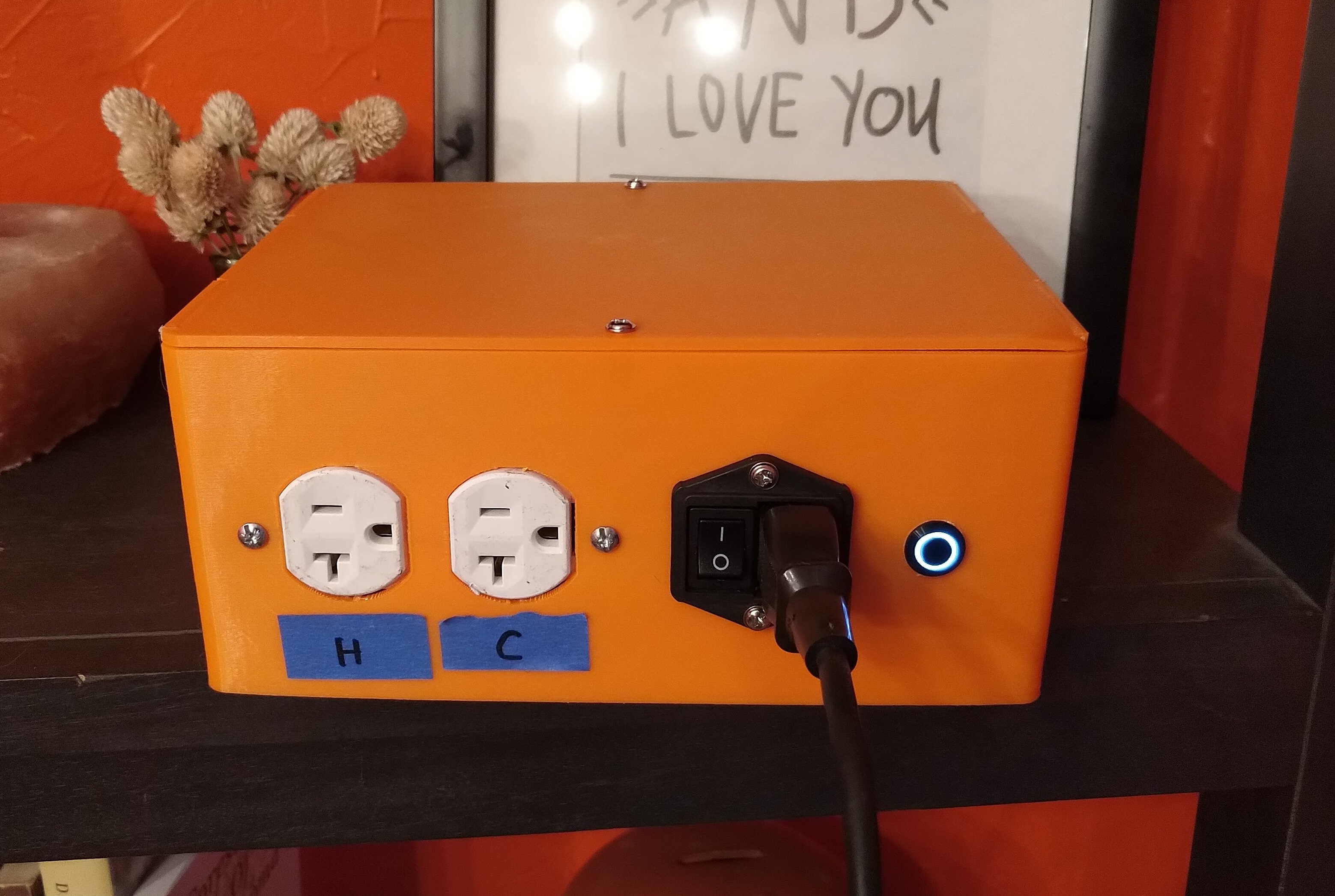
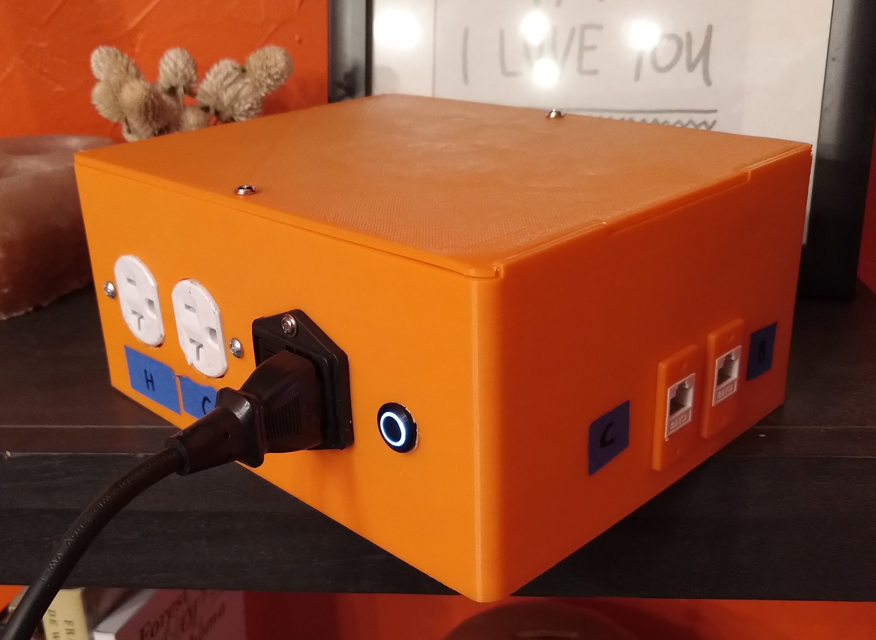
Finally got the enclosure printed, it finished this morning. Wired and mounted everything and it's alive!!

Still printing a lid and some retainers for the RJ45 keystones, and there was an issue with one of the mounts for the Uno, but over all I'm pretty happy with it.

.stl, .step, and .f3d files can be found on Thingiverse: BrewPi Remix Enclosure by dufflebum

IMG_20201212_131534.jpg


Mount Issue
IMG_20201212_143956.jpg
 
I think I finally got it ready for it's first batch of beer. Finally got a lighted momentary switch for shutdown, and wired the LED to GPIO22 and a ground, and added gpio=22=op,dh to the config.txt file. I'll probably go back in and modify the enclosure design to include Heat and Cool labels for the outlet, as well as Chamber and Beer for the RJ45 jacks, but I'm not going to print it and move everything just for that.

IMG_20201217_170248.jpg


IMG_20201217_170257.jpg


I reached out to @100amps to find out how he made such pretty diagrams for the wiring (Adobe Illustrator for those that are wondering), and he was kind enough to share his latest one, which I then modified using Inkscape to show my own build.
Okie-BrewPI-Remix.png
 
That looks great!

I need to figure out how to design in my supports. That seems to come out much better.

The pushbutton for the Pi is a gamechanger.
 
That looks great!

I need to figure out how to design in my supports. That seems to come out much better.

The pushbutton for the Pi is a gamechanger.

Thanks! This was my first time designing in supports and it was actually pretty easy. This video was helpful for me,
He uses Solidworks, and I use Fusion360, but the concept is the same.

Basically I offset from the bottom of the hole .2mm (or whatever your layer height will be), then extrude to .2mm below the top of the hole, with a 1mm on each side of the support extrusion for easier removal.
 
Is it possible to embed text labels on the surface for those connectors & ports?
Like "Heat" and "Cool" (or at least "H" and "C") above the duplex sockets?

Cheers!
 
Is it possible to embed text labels on the surface for those connectors & ports?
It is - I was trying not to pile on because right now he's looking at those pieces of tape and eventually it will get to him enough to re-make it. :p

The problem is: I'll bet he's got a > 1 day print there. If I were to guess, it's only about $5 in material, but tying up your printer for another day for an H and C is an emotional decision he needs to make. :D
 
Yeah, you need to do something about those H and C labels. The designer in me is screaming. I suggest looking for some red painters tape for the H label. :cool:
 
For the RJ45 jacks it says you can wire them in series like you did. That's actually parallel. But that's nitpicking.
 
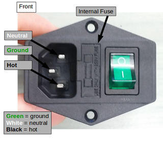
An enhancement I recommend is using a fused IEC power inlet. Say 8-10 amp fuse. But make sure it's one that has legitimate safety certifications. CSA/UL or whatever. The only way to ensure those certs are legit is to buy it from a responsible supplier. (Mouser, Digikey, etc.)

iec.png
 

Latest posts

Back
Top