2 pid, 1 ssr

Homebrew Talk - Beer, Wine, Mead, & Cider Brewing Discussion Forum

Help Support Homebrew Talk - Beer, Wine, Mead, & Cider Brewing Discussion Forum:

This site may earn a commission from merchant affiliate links, including eBay, Amazon, and others.

scottstribling

Active Member
Joined
Nov 10, 2011
Messages
31
Reaction score
2
Location
Phenix City
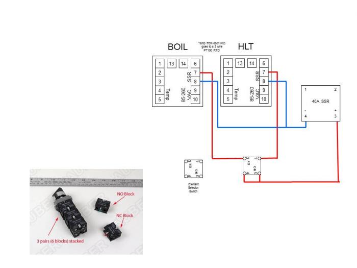
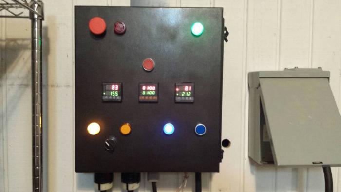
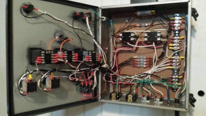
I have built my control box....and have found a small issue. I have a 30a system with 2 4500W elements (HERMS). Only 1 element will be on at any given. I have a PID (SYL2352) for each of the HLT and the BOIL. I have one SSR and now realize that I can not wire 2 PIDs to one SSR. I have no room to add another SSR and bigger heat sync. Anyone have an idea? One I had was to wire both PIDs to the SSR and use a power switch on each PID to stop any signal being passed to the SSR. I have attached a wiring diagram.

2 PID 1 SSR.jpg
 
I would add another set of the NO blocks to your element selector switch and run the input from your PIDs into them. Then run both of the outputs from that switch to the SSR. That way, only the PID associated with that element will actually feed into the SSR.
 
PJ has a diagram showing how to do this. Check out the pj diagram thread. Basically there's one ssr, one pid, two elements. A two way switch controls which element gets the power.
 
I used that wiring diagram. Im just not sure how to add the additional NO blocks on the current switch to control the SSR with 2 PIDs.
 
Im don't have a way to draw it, but I will try to describe my idea using your image. You have to get new NO blocks that attach on to the bottom of the switch you have. Then you will run line 7 from your HLT PID to the switch marked 3 on the left side. The output, marked 4 on the left side, would go to the + on the SSR. For the BK, you would do something similar, but it would go from 7 on the PID to the block on the right marked 4, and the output, marked 3, would also go to the + side on the SSR. I believe that you could then run either, or both, of the spot 8 on the PIDs to the SSR - side. Let me know if that doesn't make sense and I can try t o find a good way to draw it.
 
Im don't have a way to draw it, but I will try to describe my idea using your image. You have to get new NO blocks that attach on to the bottom of the switch you have. Then you will run line 7 from your HLT PID to the switch marked 3 on the left side. The output, marked 4 on the left side, would go to the + on the SSR. For the BK, you would do something similar, but it would go from 7 on the PID to the block on the right marked 4, and the output, marked 3, would also go to the + side on the SSR. I believe that you could then run either, or both, of the spot 8 on the PIDs to the SSR - side. Let me know if that doesn't make sense and I can try t o find a good way to draw it.

So I will add the 2 new NO Blocks onto the back of my element selector switch corrsponding to the element/PID I want to control?

NO Blocks.jpg
 
Pretty much. I did something similar with my rig 2 elements with 3 temp controllers and a plate chiller. I use these selector switches to switch between which pid controls my second element. And the other to determine which temp probe is hooked up to my second pid so when I'm chilling I can see when to stop recirculating and start pumping to my fermenter.

ImageUploadedByHome Brew1402099951.991414.jpg
 
Sorry to bring up an old thread, but I am looking to do the same thing. I want to run two PID's. One Inkbird for my HLT and one EZ boil for my boil kettle and have a single cord. Flip the switch from one PID to the EZboil. What I dont understand is why you are blocking the signal to the SSR from one PID to the other. If I have a 3 way selector switch, and I am able to switch the power from one PID to the other PID, why do you need to break the signal to the SSR from one PID to the other? If I heat the HLT first, the unhook the cable from my element on the HLT and plug it into the element on the boil kettle, then flip the 3 position switch to the EZboil, the Inkbird PID goes off and the EZboil comes one.
 
Sorry to bring up an old thread, but I am looking to do the same thing. I want to run two PID's. One Inkbird for my HLT and one EZ boil for my boil kettle and have a single cord. Flip the switch from one PID to the EZboil. What I dont understand is why you are blocking the signal to the SSR from one PID to the other. If I have a 3 way selector switch, and I am able to switch the power from one PID to the other PID, why do you need to break the signal to the SSR from one PID to the other? If I heat the HLT first, the unhook the cable from my element on the HLT and plug it into the element on the boil kettle, then flip the 3 position switch to the EZboil, the Inkbird PID goes off and the EZboil comes one.
I don't recommend a single cord to be switched between two elements, but if you are committed to that plan, then the best thing to do is switch the PID/EZBoil signal to the SSR, rather than powering the controllers on/off to do the switching. This way the controllers can be programmed and be in a known state before you connect them to the SSR. You will still need a main disconnect between the incoming power and the SSR and element, since SSR's tend to fail in the on mode. Also, SSR's switch current, not voltage, even with the SSR off, there is enough voltage to give you a good shock.

Do you have a schematic for the panel you plan to build?

Brew on :mug:

Doug,

That makes sense to switch the PID signals to the SSR. I like it. I dont have a schematic, but bear with me for a second.
Main power to contactor that is switched on with main power switch. Main power switch turns on both PID's. 3 way selector switch with 2 N/O. (on, off, on) The 3 positions switch, will switch the second contactor between the main contact and SSR. Left will be for PID, center off, Right for EZ/boil. The second N/O on the 3-pos switch will switch the signal on SSR as in post #7 above.
 
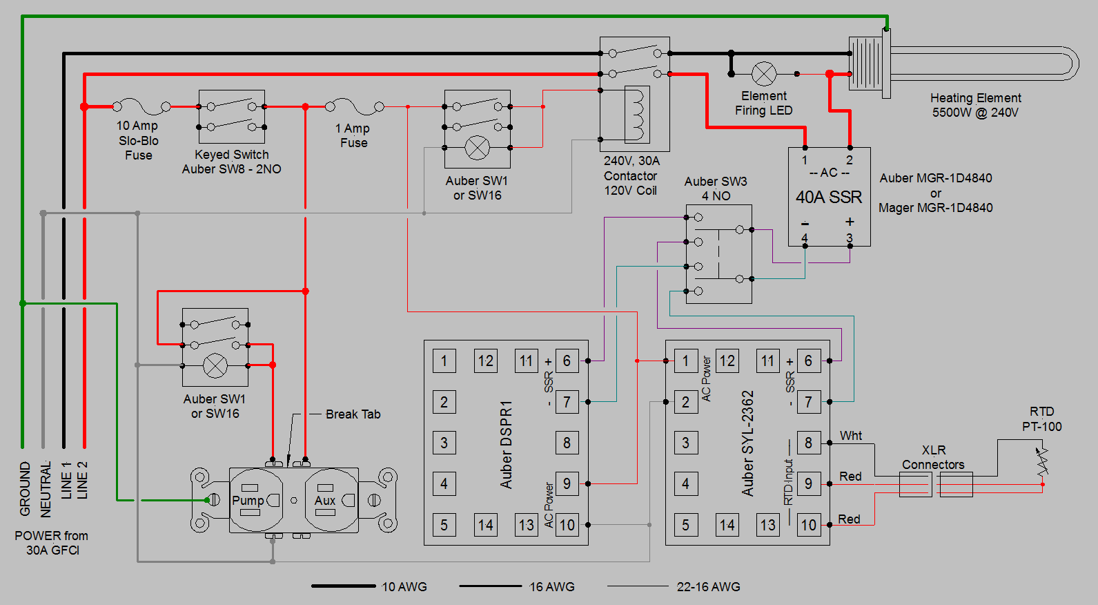
You only need one contactor for your system. The main power switch connects power to the "control power bus." The control power bus feeds power to the PID and the EZBoil, and to the element enable switch. The element enable switch connects power to the element power enable contactor, and the element power enable contactor feeds the SSR and element(s). You could combine the element enable switch in the selector switch, but then you need four NO blocks on the selector switch (I don't think you understand how the selector switch is wired.)

The following schematic should give you some idea of what I am talking about:

1-PID 1-DSPR 1-Element 1-Pump 1-Aux  120V-240V rev 3.PNG


We could leave out the SW1/SW16 switch and use 2 of the NO's on the selector to perform the same function. We would then just put the positive SSR control signals thru the selector, and common the negative control signals. I should redraw the selector switch to more accurately depict how it is actually configured.

Let me know if you have questions, or need an updated schematic.

Brew on :mug:
 
Great Schematic, Thank you. This is exactly what I need. I plan to use a 3 position double pole after the main keyed switch. It will turn on the contactor in position 1 or 2 and off in center position. It will also switch the #6 lead coming off the PID's. I dont see a need to disconnect #7 from the PID's. Since #7 is the negative and will not complete either circuit when it is switched.
 
Last edited:
Back
Top