
Hey guys, I know this is my first post, but I have been using this site for a while now doing as much research as possible. I am in the middle of trying to wire up my control panel and am having a little difficulty with the PID's. I have a friend that uses these for work, and was able to grab me a couple for free. However, that means not only do they not match what Kal used, but I have two different styles. Please let me know if my logic or thoughts are incorrect.
Now when it comes to wiring, I understand the basics pretty well, especially when its accompanied with the great pictures and information that Kal has provided.
I cannot for the life of me figure out the alarm set up.
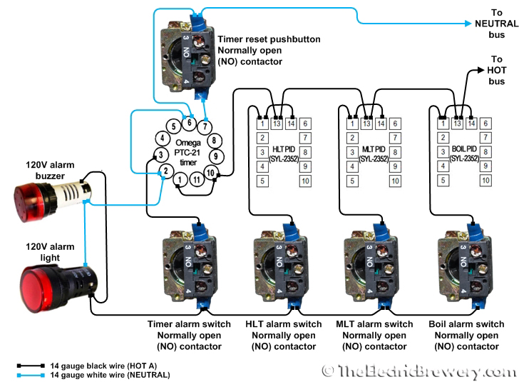
Sometimes it helps me to talk it out. In this case it seems to me that power is coming into each PID on 13 so the alarm has power, and the reason 14 and 1 are all jumped together is because most of these PID's have two alarm settings. By jumping them when either alarm trips, on any of the PIDS it will make a circuit causing the red light and horn to go on. The neutral is just being jumped through so it can share a line back to the bus board.
One of the PIDs I have is a Mypin T. here is the wiring diagram:
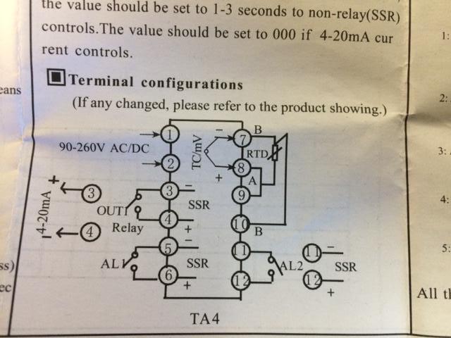
On this one would I have to hook power from the hot bus to #12 and jump it to #6 so both alarms have power? Then jump #11 and #5 and hook that to the alarm switch?
The other style I have is an Omron E5CN Here is a copy of that wiring Diagram.

On this one would I just have to hook the line from the hot bus to #8? And then Jump #7 and #6 to the alarm switch?
Also while I have you looking at them. On the Mypin, the thermocouple hooks up to #7,#8,#9? And the output to the SSR comes from #3 and #4?
And on the Omron the thermocouple hooks up to #3,#4,#5 and #1,#2 hook up to the SSR?
I really appreciate any help you guys can give me. Thanks
Now when it comes to wiring, I understand the basics pretty well, especially when its accompanied with the great pictures and information that Kal has provided.
I cannot for the life of me figure out the alarm set up.
Sometimes it helps me to talk it out. In this case it seems to me that power is coming into each PID on 13 so the alarm has power, and the reason 14 and 1 are all jumped together is because most of these PID's have two alarm settings. By jumping them when either alarm trips, on any of the PIDS it will make a circuit causing the red light and horn to go on. The neutral is just being jumped through so it can share a line back to the bus board.
One of the PIDs I have is a Mypin T. here is the wiring diagram:
On this one would I have to hook power from the hot bus to #12 and jump it to #6 so both alarms have power? Then jump #11 and #5 and hook that to the alarm switch?
The other style I have is an Omron E5CN Here is a copy of that wiring Diagram.
On this one would I just have to hook the line from the hot bus to #8? And then Jump #7 and #6 to the alarm switch?
Also while I have you looking at them. On the Mypin, the thermocouple hooks up to #7,#8,#9? And the output to the SSR comes from #3 and #4?
And on the Omron the thermocouple hooks up to #3,#4,#5 and #1,#2 hook up to the SSR?
I really appreciate any help you guys can give me. Thanks
") I can't recall seeing anybody's setup ever using a 2nd alarm.
I can't recall seeing anybody's setup ever using a 2nd alarm.