Low bucks DIY multiple probe digital thermometer

Homebrew Talk - Beer, Wine, Mead, & Cider Brewing Discussion Forum

Help Support Homebrew Talk - Beer, Wine, Mead, & Cider Brewing Discussion Forum:

This site may earn a commission from merchant affiliate links, including eBay, Amazon, and others.

J_Hanna

Well-Known Member
Joined
May 24, 2014
Messages
68
Reaction score
26
Location
Harrah
1_Display.jpg
Digital brew thermometer project:

While there are lots of great analog thermometers available, digital thermometer choices are much more limited.

I looked at all of the digital thermometers I could find and found that the ones I liked I couldn't afford and the ones I could afford I didn't like ( this happens to me so often I should translate it into Latin and use it for my family motto! perhaps: "Non Affordom Primo, Nil Desirus Crapola" )

What I want in a digital thermometer is pretty basic, accurate readings and an easy to read display.

A year or so ago I started playing around with Micro computers. There are several popular ones out there, 3 of the most popular are the "Raspberry Pi", the "Arduino" and the "Beaglebone/Beaglebone Black". All are fairly inexpensive and all have a large fan base and tons of documentation.

Looking at the cost of available thermometer hardware I determined that it should be possible to build a customizable digital thermometer with multiple inputs/probes using one of these micro computers for around $50.00 or less depending on how much of the hardware needed you already have. ( Note: you MUST have a spare laptop/desktop computer to make this project work, when not using the digital thermometer the computer can be used for other purposes. The laptop I'm using for my setup is an elderly Dell Inspiron 6000 with a Centrino processor running the Xubuntu Linux OS, I'm sure it's possible to run this from a Windows or Mac system if that's what you have, however I don't have the particulars on how to do it. )

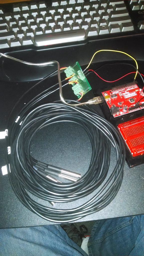
The 2 key words in the previous statements are "customizable" and "multiple", by customizable I mean that, depending on your programming skill, you could write in extras such as temperature limits and alarms, tie ins to relays to control the heating elements, data logging to graphs and other uses I haven't even thought of yet. By multiple I mean the number of probes you can add are up to you, in my case I wanted to set up a 3 probe system for AG brewing to monitor HLT, MLT and BK temps from a central location.

As an added bonus, the display on my setup is VERY easy to read, each character is about an inch tall and I've set it up with red letters on a black background, this is easily changeble in the code if you'd like a different combination.

Of the micro computers listed I decided to go with the Arduino ( ar-dwee-no ) as it is generally considered the more robust platform.

Before you consider trying this project be aware that you need average or above computer skills and are comfortable installing software, installing hardware and are familiar with programming concepts. In particular you need to be familiar with the Linux operating system, if you don't fell comfortable with all of this then you might want to refer this to one of your more nerdy friends! :)

Also be aware that this project will take at least a couple of hours to complete. If you like playing around with computers and possibly learning new stuff then it'll be fun, otherwise you might want to give it a skip.

Hardware:

What's needed depends on how you want to use the setup but the basic equipment is...

A laptop/desktop computer running Linux as mentioned before.

The Arduino - SainSmart UNO R3 ATmega328P Development Board + USB Cable ( $16.80, free shipping w/ $35 total purchase. )
http://www.amazon.com/gp/product/B00E5WJSHK/?tag=skimlinks_replacement-20

Solderless BreadBoard, 400 tie-points, 4 power rails, 3.3 x 2.1 x 0.3 in ($5.95, free shipping w/ $35 total purchase )
http://www.amazon.com/gp/product/B005GYAIES/?tag=skimlinks_replacement-20

Vktech 5pcs DS18b20 Waterproof Temperature Sensors Temperature Transmitter ( $7.80 at Amazon with free shipping from China )
http://www.amazon.com/gp/product/B00CHEZ250/?tag=skimlinks_replacement-20
( This is a 5 pack, singles are like $4.00 each, might as well get 5 in case there are any duds. Order these first as it takes a few weeks to get them. Note: these particular probes are 39" long but there are longer probes available, for example the 9' long model is $16.79 for 5, I'm hoping the 39" ones will work on the brew stand I'm building. )

4.7K pull up resistor ( 1 ) ( these should be available at Radio Shack for like 50 cents, I bought a variety pack of resistors from Amazon for $9.99 that has 400 resistors in 16 different sizes that I will be using for other projects. The variety pack is overkill for this application but here's a link to the one I bought. )
http://www.amazon.com/gp/product/B00E9Z0OCG/?tag=skimlinks_replacement-20

You need 3 male/male breadboard jumper wires, I'm sure these are available at Radio Shack for probably 50 cents each, or multi-packs are available at Amazon, here's one with 100 jumpers...
Wosang Solderless Flexible Breadboard Jumper Wires M/M 100pcs ( $6.00, free shipping w/ $35 total purchase )
http://www.amazon.com/dp/B005TZJ0AM/?tag=skimlinks_replacement-20

Hardware setup:

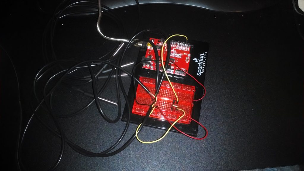
On the breadboard connect the 4.7K pull-up resistor between data and power. To do this, bend the resistor leads into a "staple" shape that spans the breadboard points you wish to use ( in my setup I selected row 13 for data, row 15 for power and row 17 for ground, see photo, by skipping a row between each one I allow myself a little more working room ), clip the leads to approximately 1/4" long, insert the resistor into the mounting points.

2_Box1.jpg

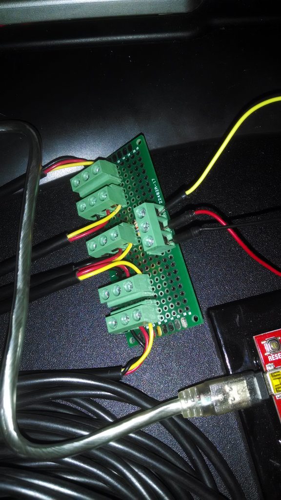
I have been told that there are different wiring versions of the probes, such as...

Red: 5Vdc, Black: Ground, White: Data
Red: 5Vdc, Yellow: Ground, Green: Data

mine was...

Red: 5Vdc, Black: Ground, Yellow: Data

If you get yet another configuration you might have to experiment to determine which is which.

Connect M/M jumpers from the 5V connector on the Arduino to the breadboard point you've selected for power, data pin 2 on the Arduino to your breadboard data point and Arduino ground to your breadboard ground point .

3_Box2.jpg

Connect each probe's power, data and ground wire to the corresponding breadboard point. Note: You may have to trim away some insulation to expose enough wire to get a good insertion in the breadboard, I trimmed the insulation back on mine and then, using a soldering iron, applied a little solder to the exposed wires to thicken them up for a better fit.

4_Box3a.jpg

It may be necessary to use zip ties to secure the wiring to prevent disconnects, another method would be to borrow the wife's hot glue gun and permanently attach the wires to the breadboard ( make sure everything works first ). On my setup I used some double sided tape to secure the wires. Also in my setup I've mounted everything into a small plastic box to protect from possible splashes on brew day.

5_Box4.jpg

6_Probes.jpg

Software setup:

One programming language commonly used in Linux is called "Python" and at the end of this write up I've provided the Python code I've written for this project. Note: if you want to change the code to add other features please feel free to do so, just be aware I am not a professional programmer ( and not much of an unprofessional one either ) so if you have questions about changing the code or adding to it please direct your questions to someone more knowledgeable about Python than myself ( "my Python Kung-fu is not the best" ).

I'm using version 2.7.6 of Python. Python is pre-installed in most versions of Linux, you will however need to add some modules to make this project work.

To display the output in easy to read GUI windows it's necessary to load the "TKinter" module, to do this open a Linux terminal window and enter...

sudo apt-get install python-tk

the "Pyserial" module is required to communicate with the serial port that the Arduino sends data to, instructions to download and install this module are here...

http://pyserial.sourceforge.net/pyserial.html

The Python code I'm providing will need to be modified to reflect which device your system uses for the serial port output, in my case it's "/dev/ttyACM0' but yours will most likely be different, when you install the Arduino IDE software on your system there is a step that determines the correct device for you to use.

To facilitate editing your Python code there is a IDE ( Integrated development environment ) you can use called IDLE which is pre-installed on most Linux systems, IDLE I believe is a universal IDE and may need to be set for Python. ( Note: IDLE is separate program from the Arduino IDE also needed. )

The programming language used by the Arduino is "C/C++" and again at the end of this write up I've provided the C code I've written for this project. Note: As before, if you want to change the code to add other features please feel free to do so, just be aware I am not a professional programmer so if you have questions about changing the code or adding to it please direct your questions to someone more knowledgeable about C/C++ than myself.

The Arduino code provided will also need to be modified, you'll need to specify the addresses of your probes. For example the address of one of my probes is...

DeviceAddress Probe01 = { 0x28, 0x14, 0xB3, 0x5C, 0x06, 0x00, 0x00, 0x83 };

The Hex code listed is the serial number of the probe. Each probe contains a DS18B20 transistor and each transistor has a unique serial number, directions on obtaining your serial numbers will follow.

To edit and install your Arduino code you must install the Arduino IDE available at...

http://arduino.cc/en/main/software

Links to installation directions are located on that same page.

Once you have the Arduino IDE installed there are 2 modules required for this project...

The "Dallas Temperature Control Library" at...

http://milesburton.com/Main_Page?title=Dallas_Temperature_Control_Library

and the "One wire library" at...

http://www.pjrc.com/teensy/td_libs_OneWire.html

After you've installed these libraries, from the Arduino IDE "file" drop down menu select the "/examples /Dallas Temperature /Tester" file and upload the file to the Arduino, on the right side of the IDE window is a small magnifying glass icon, click this icon to open the serial monitor window. De-select "autoscroll" in that window and scroll up to the top of the data. There you will find the serial number/addresses of your probes ( assuming they are hooked up correctly ).

Edit the Arduino code I've provided and enter your correct address information in place of mine, upload the code to the Arduino. Note: You can open the serial monitor window previously described to see the raw data coming from the probes but do not open the serial monitor window while the Python program is running as this will crash the Python program.

Once the code is loaded into the Arduino it immediately begins executing and starts filling the serial port read buffer with data, you should have the Python code ready to start at the same time as the Arduino in order to keep the the data being displayed in sync with the actual data coming from the probes.

The Arduino hold it's programming in memory and it immediately begins executing the code when power is applied either by turning on an external power supply connected to the Arduino ( not used in my example ) or by plugging the USB cable the Arduino is attached to into the host computer. To empty the serial port read buffer just unplug the Arduino USB cable.

Just to be clear, once the code is loaded on the Arduino and running correctly there is no need to reload the code onto the Arduino ever again or to ever launch the Arduino IDE program again.

To launch the Python program start IDLE and open the program code you previously edited and saved ( you did save it didn't you? :) then start the program from the run menu. You can also set the file up to run just by double clicking it, I haven't gotten around to doing that yet, I'm just happy it works!

In my code I've set it up for the Arduino to poll the probes once every 4 second at which time it writes a separate line of data for each probe ( i.e. 3 lines ), the Python code reads one line of code every second which means it takes slightly over 3 seconds to read those 3 lines of code. Depending on how much of a head start the Arduino has over the Python program the Python program will eventually catch up on the data already written to the serial port read buffer. It may be possible to send a purge command to the buffer when the Python program starts but I haven't spent a lot of time looking into this as it's not really a problem as long as the Python program is started in a timely fashion after the Arduino is powered up.

If you are an accomplished programmer you may wish to change the code to display all three probe data streams at once instead of cycling through them as I've set it up. I had tried writing 3 separate programs, one for each probe's data to be displayed in a separate window, but when I ran the 3 programs I would start getting garbage after just a couple of seconds. I believe that the garbage was being produced when all 3 programs were trying to access the serial port read buffer at the same time, causing collisions.

BTW, It took me a couple of weeks to get my setup working, mostly because I haven't written any code in over a decade. It took several days to get the mental cobwebs blown out :)

7_Display3.jpg

8_Hot.jpg

Cheers!
---------------- Python code ----------------
from Tkinter import *
import serial

root = Tk()
var = StringVar()
ser = serial.Serial('/dev/ttyACM0', 9600)


class App:

def __init__(self, master):
self.y='0'
self.t=ser.readline()
if 'P1' in self.t:
self.y='HLT = ' + self.t[3:8]
if 'P2' in self.t:
self.y='MLT = ' + self.t[3:8]
if 'P3' in self.t:
self.y='BrK = ' + self.t[3:8]
self.x=str(self.y)
self.x+=u'\N{DEGREE SIGN}''F'
self.w = Label(textvariable=var, height=3, width=14, bg="Black", fg="Red", font=('Verdana', 80, 'bold'))
var.set(self.x)
self.w.pack()
self.id = self.w.after(1000, self.timer)

def timer(self):
self.t=ser.readline()
if 'P1' in self.t:
self.y='HLT = ' + self.t[3:8]
if 'P2' in self.t:
self.y='MLT = ' + self.t[3:8]
if 'P3' in self.t:
self.y='BrK = ' + self.t[3:8]
self.x=str(self.y)
self.x+=u'\N{DEGREE SIGN}''F'
self.w.config(textvariable=var)
var.set(self.x)
self.id = self.w.after(1000, self.timer)

app = App(root)

root.mainloop()


---------------- Arduino code ----------------
#include <OneWire.h>
#include <DallasTemperature.h>
#define ONE_WIRE_BUS_PIN 2

OneWire oneWire(ONE_WIRE_BUS_PIN);
DallasTemperature sensors(&oneWire);

DeviceAddress Probe01 = { 0x28, 0x14, 0xB3, 0x5C, 0x06, 0x00, 0x00, 0x83 };
DeviceAddress Probe02 = { 0x28, 0x46, 0xD4, 0x5B, 0x06, 0x00, 0x00, 0x05 };
DeviceAddress Probe03 = { 0x28, 0x65, 0x6E, 0x5C, 0x06, 0x00, 0x00, 0x9E };

void setup()
{
Serial.begin(9600);
sensors.begin();
sensors.setResolution(Probe01, 12);
sensors.setResolution(Probe02, 12);
sensors.setResolution(Probe03, 12);
}

void loop()
{
delay(4000);
sensors.requestTemperatures();
Serial.print("P1 ");
printTemperature(Probe01);
Serial.println();
Serial.print("P2 ");
printTemperature(Probe02);
Serial.println();
Serial.print("P3 ");
printTemperature(Probe03);
Serial.println();
}

void printTemperature(DeviceAddress deviceAddress)
{
float tempC = sensors.getTempC(deviceAddress);
if (tempC == -127.00)
{
Serial.print("Error getting temperature ");
}
else
{
Serial.print(DallasTemperature::toFahrenheit(tempC));
}
}

---------------------------------------------------------------------------
 
Last edited by a moderator:
Awesome! I might just do this. I've got plenty of linux systems laying around, and have dabbled in python, but sadly I have never done C (I know, what kind of linux nerd has never done C right?)

Great writeup here! Can I crosspost this to reddit? If not, will you crosspost this to reddit?

Edit: I see you are in Harrah, which happens to be only a few miles from me. Hmm...

skunkfunk,
I guess it'd be okay for you to crosspost if you'd like, thanks!
If I ever get my 3 tier gravity fed rack welded up I'll invite you out for the trial run. My workshop isn't heated and I just can't get motivated to do much work on it when it's cold so it'll probably be a few months...:(
 
skunkfunk,
I guess it'd be okay for you to crosspost if you'd like, thanks!
If I ever get my 3 tier gravity fed rack welded up I'll invite you out for the trial run. My workshop isn't heated and I just can't get motivated to do much work on it when it's cold so it'll probably be a few months...:(

It is done.

We need to have an OKC area beer swap or something. I want to try other people's ****.
 
Spent some time playing with a small LCD screen this morning and determined that adding one to the thermometer would be pretty easy.
The plus side of using one of these displays would be that the thermometer could be completely self contained as there would be no need for a PC. It could even be powered by a standard 9V battery for more portability.
The negative side would be losing the large display and potentially losing some future functionality.

LCD_display.jpg

The small 2 line by 16 character display shown goes for about $12. This particular one ( Sain Smart LCD2004 ) only requires 2 data lines and has the capacity to be daisy chained with other displays, meaning you could have a separate display for each probe.
I don't plan to use the small display myself but if anyone would like to try it I could probably help modify the Arduino code to make it work for you.

9V_Battery.jpg

A 9V adapter is $3.99 at Radio shack.

comparison.jpg

Here's a comparison between the small display and an average sized thermometer display.

In a week or so I will be receiving a Bluetooth adapter that I hope to incorporate into the thermometer, the BT adapter will allow the thermometer to be physically disconnected from the PC giving greater placement flexibility but still retain the PC's larger display.

Cheers!
 
Just_Thermo_bb.jpg

Here's the board layout for adding a LCD, just 4 extra wires. I used a great program called "Fritzing" to generate this graphic which is much neater than anything I could do by hand.
 
The Bluetooth module I mentioned previously came in yesterday, I went with a JY-MCU module which is pretty popular. $9.99 at Amazon, free S&H with $35 order...

http://www.amazon.com/gp/product/B0093XAV4U/?tag=skimlinks_replacement-20

You will also need 4 m/f jumper wires, 2 m/m jumper wires, and 2 resistors ( more on this in a moment ) all of which are available at Radio Shack. It should go without saying that the laptop/desktop computer you're using must have Bluetooth. If it's not there are plenty of inexpensive USB Bluetooth "dongles" available for less that $10 each. I've used the $7.99 Edimax EW-7811Un for other projects and it worked great so I suppose it would work fine for this as well, my laptop has built-in Bluetooth so I can't say for sure.

http://www.amazon.com/dp/B003MTTJOY/?tag=skimlinks_replacement-20

Finally you will need a power source, previously the thermometer ran off of the 5V supplied by the USB port. You have several options, one is the 9V battery I mentioned in my previous post but any power supply in the range of 7 to 12V will work, they just have to have a 2.1mm power connector with positive center. I'm using a 9V/500mA brick I had laying around which works fine, if I were buying one specifically for this application I'd want about a 9V/1000mA model. Here's one for $5.57...

http://www.amazon.com/dp/B00CP1QLSC/?tag=skimlinks_replacement-20

The reason you can't use a 5V PS is that the Arduino needs at least 7V for the internal voltage regulator to work, the Arduino wasn't regulating the USB 5V since the computer supplying that power was. Note: the higher the input voltage the more heat the Arduino will produce regulating the voltage, I'd stay away from 12V if you have other options, it'll work but it's probably not good for the Arduino.

Another option is a 9V output AA battery box, the advantages of this box is that it has a nice on/off switch and has longer battery life than a standard 9V battery. $5.83 at ( where else ) Amazon.

BatteryBox.jpg

http://www.amazon.com/gp/product/B00HGAL0L0/?tag=skimlinks_replacement-20

Hardware Setup:

Hardware setup is fairly straight forward; the only hiccup with using this particular BT module is that the module wants a 3.3V level on the data lines. Data out voltage is not a problem as it is controlled by the module itself but the data in, coming from the Arduino, is at 5v. The work around for this is a simple voltage divider which uses two resistors. There is no specific values for the transistors used except that one should be double the value of the other one, for example you could use a 10K and a 20K, a 5K and a 10K, etc.
The closest I had was a 4.7K and a 10K which puts the output at a 3.4V level instead of 3.3V which should be close enough as there are plenty of people on the internet who swear that the module works fine at the full 5V coming from the Arduino. I believe they are right that it will work at 5V but I'm pretty sure that the life of the module will be a lot shorter. Again, the resistor values are up to you.

Setting up the voltage divider is easy. On the breadboard connect one side of the 10K resistor to ground, connect the other side of the 10K resistor to the RXD line going to the Bluetooth module AND one side of the 4.7K resistor, the other side of the 4.7K resistor connects to the TX line from the Arduino.

Divider.jpg

Here's a schematic of the voltage divider.

layout3.jpg

Here's the physical board layout with the BT adapter and voltage divider added. Which is a lot easier to read than this... :)

guts.jpg

Software Setup:

Software setup is also fairly straight forward, rather that provide the same information here I refer you to this webpage...

http://www.uugear.com/portfolio/bluetooth-communication-between-raspberry-pi-and-arduino/

Even though they are referring to a Raspberry Pi these instructions should work on any Linux system, they certainly worked great on my Xubuntu Linux laptop.

The gist of the setup is to identify the addresses of both Bluetooth devices and to bind them to a device location which you can then call from the Python program.

Note: You can't have both the USB cable and the Bluetooth adapter connected at the same time as the Arduino only supports one comm port at a time. When you need to upload code to the Arduino disconnect the BT adapter, reconnect the USB cable and select the correct comm port in the Arduino IDE.

After you have verified that you can communicate between the 2 devices modify the Python program, change this line...

ser = serial.Serial('/dev/ttyACM0', 9600)

to

ser = serial.Serial('/dev/rfcommX', 9600)

Where rfcommX is the dev location of the Bluetooth adapter connected to the Arduino, mine was "rfcomm0".

Assuming everything's wired up right then the Python program should run the same way it did using the USB cable, mine does.

Range on this should be about 15-20 foot which should be far enough away from the kettles to protect the computer from splashes, and if it's not then you probably have bigger problems than just getting your computer wet.:)

There are also WiFi adapters available, but in my case that wouldn't work as my home WiFi network won't reach out the workshop where I brew. ( darn it. )

Cheers!
 
Last edited by a moderator:
The battery pack came in, attached it with velcro. The next upgrade I'm looking into is writing an Android app to view the temperature data on my phone, that might take a while...

Battery_Pack.jpg
 
After a couple of weeks of banging my head against the wall I was finally able to write a small program to display the thermo output on an android device via bluetooth, here's what the raw data looks like coming in on my phone. Just need to write the part of the program that displays the data in a slightly easier to read format. :)

phone2.jpg
 
Made some progress with the Android program, it's finally in a usable state. Still have some minor tweaking such as converting the probe number to the name of the kettle ( HLT, MLT or BrK ) and adding a degree sign at the end, not really necessary I know but hey I've put this much time into I might as well finish it.

Here's 2 views of the running program in portrait and landscape. This is on my 9" tablet. I found out that there's 2 different processors used in tablets, ARM and ATOM ( Intel ); I wrote my script to run on an ARM as that's what I have.

AndroidDisplay.jpg

AndroidDisplay2.jpg

The next step in the project is a hardware re-do, I've decided that the probes I have set up now probably won't be long enough for my brew stand so I've got some 2 meter long cables that I'll be using in my next version. I'm also going to use a Arduino Nano board which is about 1/4 the size of the Uno board, which will give me more room in the box I will be using, a nice waterproof model. Also plan to solder all connections to make it a bit more rugged.

Nano-Uno.jpg

Waterproof.jpg

Cheers!
 
On completing my wireless multi-probe brew thermometer project I knew that even though it was completely usable there were aspects of the hardware setup that needed improvement.

1. The plastic cough drop box I used is very flimsy and the lid comes open too easily.
2. The components are held in place using double sided sticky tape and velcro, I'm pretty sure if I ever dropped it everything would come loose.
3. It isn't as water resistant as it should be given the environment it's to be used in.
4. There's no easy way to mount it to a brew rack except for bungie cords or more velcro.
5. There's no way to tell if the unit is powered on or off just by looking at it.
6. The one meter long probes I used might not be long enough.

So I went back to the drawing board to address these issues. As mentioned earlier I found a $4.00 water tight enclosure on Amazon that seals using screws, it also has mounting tabs. Using this enclosure takes care of issues 1, 3 and 4. To address issue 2 I decided to move from a breadboard to a prototyping board that allows me to hard solder the components together.
The overall size of the new enclosure is slightly smaller than the combined size of the first setup ( i.e. the component box and battery pack ) . The new enclosure is 4" Long x 2.75" Wide x 2" High, with .625" mounting tabs for an overall length of 5.25". To fit everything into the new enclosure I went from a battery pack with 6 AA batteries to an internally mounted single 9V battery; of course the run time between battery replacement is much shorter but I'd think it possible to get 2 or 3 brew sessions out of a single battery so it's probably a minor compromise. I also went with a smaller micro-processor board using a Arduino Nano instead of an Arduino Uno ( same price ), both micro-processors function identically and run the same sketch code. I found a $4.00 rocker switch that lights up when power is on which takes care of issue 5 and lastly, to address issue 6, I went with two meter length probes for the "Mark II". Note: the cost of the build only went up about $10.

Mark II build notes:

MK2a.JPG

Photo 1: Made base plate from aluminum stock. Using a base plate makes assembly easier as everything can be put together outside the enclosure. Cut down prototype board to 6cm by 6cm and drilled standoff holes. Assembled same. Inserted terminal blocks used for probe connection, using soldered on terminal blocks will allow easy replacement of probe if one fails.

MK2b.JPG

Photo 2: Verified base plate and proto board fit in enclosure.

MK2c.JPG

Photo 3: Verified battery location and fit.

MK2d.JPG

Photo 4: Cut openings in enclosure for switch and probes. Switch is mounted flush to base plate and when fully inserted will hold base plate in place with no need for other fasteners.

MK2e.JPG

Photo 5: Worked out component placement.

MK2f.JPG

Photo 6: The completed assembly, less the cover. Note that the Bluetooth module is mounted on a female pin strip soldered to the proto board. This will facilitate removing the BTM to allow USB connection for downloading sketch changes. Also note the lit power switch and program running on the Android tablet running in background, works!

I really can't think of anything else that needs improvement so hopefully this is the last entry for the project, cheers!
 
J_Hanna,

Have you made the android program available anywhere?

Also, Is there any reason why one could not leave the unit hooked to the USB? I have a dedicated Linux computer for brewing and fermentation control. I cannot think of any reason I could not skip the Bluetooth part of the build and leave it connected to the computer all the time. Maybe start a web server on the computer, build a webpage from the inputs and be able to access it from any device? Any problems with that I am not seeing?

Thanks,
Cody
 
bionut-
The joy of this setup is that the build is the same whether it's 1 probe or 10, you'd just hook up one probe instead of 3 and only send 1 read command in the Arduino code.
Cody-
I didn't post the Android code because part of it is in .html which might cause problems on this board. If you'd like that .html code I could e-mail it to you. The rest of the code is a Python script that runs using an Android program SL4A which stand for "Scripting Layer for Android" which only runs on ARM based Android devices at the present time, this is not a large problem as about 90% of the tablets and phones out there are ARM based.

Here's the Android Python script...

---------------------------------

import android
import time

BT_DEVICE_ID = None

droid = android.Android()
droid.bluetoothConnect('00001101-0000-1000-8000-00805F9B34FB', BT_DEVICE_ID)

droid.webViewShow('file:///sdcard/sl4a/scripts/example/ui.html')
while True:
time.sleep(1)
sensor_data = droid.bluetoothReadLine().result
sensor_data = sensor_data + '<br />'
droid.eventClearBuffer()
droid.eventPost('display_data', sensor_data)

--------------------------------------

You see it calls a .html file called ui.html which takes the temperature data and presents it in a nice easy to read size. Anybody that wants that .html code just send me your e-mail address.

As far as using USB on a Linux computer, just follow the build up to the point where I switched over to Bluetooth.
 
J_Hanna,

Have you made the android program available anywhere?

Also, Is there any reason why one could not leave the unit hooked to the USB? I have a dedicated Linux computer for brewing and fermentation control. I cannot think of any reason I could not skip the Bluetooth part of the build and leave it connected to the computer all the time. Maybe start a web server on the computer, build a webpage from the inputs and be able to access it from any device? Any problems with that I am not seeing?

Thanks,
Cody

Totally forgot about that last part of your post, oops! Yeah that web server idea sounds cool but not sure how you would implement it. Maybe have your brewing and fermentation software running on the main computer and then call up the temperature data from a phone or tablet you could carry around with you during the brew? Let me know if you go for it!
 
Thank you. It will be a bit, since I am going to school and rebuilding the brewery area, but I'll let you know what I come up with.
 
There's not going to be a Mark III, but if there was... :)

backpack.jpg

Found this cool LiPoly/LiIon battery setup at Adafruit which would make it super easy to make the setup rechargeable.

battery.jpg

They have different size batteries available. The 1200mAh battery, whose run time should be comparable to a standard 9V battery, is $9.95. The "backpack" recharging circuit is $4.95.

Trinket.jpg

The Adafruit version of the Nano ( the Pro Trinket ) is $9.95. Prices do not include shipping which is kinda high. The nice thing about the Pro Trinket is that there's a 3V version which should go a lot longer between recharges. The Pro Trinket is also slightly smaller than the Nano.

I'm ready for Spring to get here so I can be out in the workshop brewing instead of being stuck in the house doing this kind of stuff!
 
I got a chance to play with this a little bit today. I am going to use it a bit differently than J_Hanna, so mine has four probes and will be directly connected to a computer (no need for Bluetooth). I will be adding these probes to the extra buckets in my BrewPi fermentation chamber so I can monitor temperatures. (The BrewPi will only monitor and act on one at a time - I have room for four - six fermenting buckets depending on their size.)

A little mockup work:
ctvCltQh.jpg


And here are the changes I made to the programs.
1. Added an additional probe.
2. Changed the names of the probes.
3. Altered the size of the data window.
4. Set up five files labeled monitor.txt - monitor4.txt and set the program to write values to those files so I have a record of the temperatures.

Need to do:
1. Find a way to space out writing to the files. Once every ten or fifteen minutes should be plenty. Perhaps a counter can be used to only write to the files once every 600 iterations (10 minutes).
2. Website integration? I am not sure this is necessary. The txt files will have what I need.

The code is not copying quite right here in the forums, so here is a link to a zip file containing both of my files:
https://www.dropbox.com/s/3qq8py8ybcwg7rm/Code.zip?dl=0

Arduino Code:
_________________________________________________________________
#include <OneWire.h>
#include <DallasTemperature.h>
#define ONE_WIRE_BUS_PIN 2

OneWire oneWire(ONE_WIRE_BUS_PIN);
DallasTemperature sensors(&oneWire);

DeviceAddress Probe01 = { 0x28, 0xD0, 0x3b, 0xFB, 0x05, 0x00, 0x00, 0xFE };
DeviceAddress Probe02 = { 0x28, 0xA9, 0x78, 0xFB, 0x05, 0x00, 0x00, 0x57 };
DeviceAddress Probe03 = { 0x28, 0x53, 0x61, 0xFA, 0x05, 0x00, 0x00, 0xEA };
DeviceAddress Probe04 = { 0x28, 0x87, 0x80, 0xFB, 0x05, 0x00, 0x00, 0x6A };

void setup()
{
Serial.begin(9600);
sensors.begin();
sensors.setResolution(Probe01, 12);
sensors.setResolution(Probe02, 12);
sensors.setResolution(Probe03, 12);
sensors.setResolution(Probe04, 12);
}

void loop()
{
delay(4000);
sensors.requestTemperatures();
Serial.print("P1 // ");
printTemperature(Probe01);
Serial.println();
Serial.print("P2 // ");
printTemperature(Probe02);
Serial.println();
Serial.print("P3 // ");
printTemperature(Probe03);
Serial.println();
Serial.print("P4 // ");
printTemperature(Probe04);
Serial.println();
}

void printTemperature(DeviceAddress deviceAddress)
{
float tempC = sensors.getTempC(deviceAddress);
if (tempC == -127.00)
{
Serial.print("Erroring temperature ");
}
else
{
Serial.print(DallasTemperature::toFahrenheit(tempC ));
}
}
_________________________________________________________________

Python Code:
_________________________________________________________________
from Tkinter import *
import serial
import time

root = Tk()
var = StringVar()
ser = serial.Serial('COM11', 9600)

class App:

def __init__(self, master):
self.y='0'
self.t=ser.readline()
if 'P1' in self.t:
self.y='Probe 1 = ' + self.t[3:8]
if 'P2' in self.t:
self.y='Probe 2 = ' + self.t[3:8]
if 'P3' in self.t:
self.y='Probe 3 = ' + self.t[3:8]
if 'P4' in self.t:
self.y='Probe 4 = ' + self.t[3:8]
self.x=str(self.y)
self.x+=u'\N{DEGREE SIGN}''F'
self.w = Label(textvariable=var, height=3, width=18, bg="Black", fg="Red", font=('Verdana', 40, 'bold'))
var.set(self.x)
self.w.pack()
self.id = self.w.after(1000, self.timer)

def timer(self):
self.t=ser.readline()
if 'P1' in self.t:
self.y='Probe 1 = ' + self.t[3:8]
s = time.strftime('%m-%d-%y %I:%M:%S')
s = str(s)
f=open("monitor1.txt", "a")
f.write(str(s + " " + self.y) + '\n')
f.close()
if 'P2' in self.t:
self.y='Probe 2 = ' + self.t[3:8]
s = time.strftime('%m-%d-%y %I:%M:%S')
s = str(s)
f=open("monitor2.txt", "a")
f.write(str(s + " " + self.y) + '\n')
f.close()
if 'P3' in self.t:
self.y='Probe 3 = ' + self.t[3:8]
s = time.strftime('%m-%d-%y %I:%M:%S')
s = str(s)
f=open("monitor3.txt", "a")
f.write(str(s + " " + self.y) + '\n')
f.close()
if 'P4' in self.t:
self.y='Probe 4 = ' + self.t[3:8]
s = time.strftime('%m-%d-%y %I:%M:%S')
s = str(s)
f=open("monitor4.txt", "a")
f.write(str(s + " " + self.y) + '\n')
f.close()
self.x=str(self.y)
self.x+=u'\N{DEGREE SIGN}''F'
s = time.strftime('%m-%d-%y %I:%M:%S')
s = str(s)
f=open("monitor.txt", "a")
f.write(str(s + " " + self.y) + '\n')
f.close()
self.w.config(textvariable=var)
var.set(self.x)
self.id = self.w.after(1000, self.timer)

app = App(root)

root.mainloop()
_________________________________________________________________

This is what the monitor.txt file looks like:

02-22-15 09:22:03 Probe 1 = 74.97
02-22-15 09:23:03 Probe 2 = 74.86
02-22-15 09:23:04 Probe 3 = 74.86
02-22-15 09:23:06 Probe 4 = 72.84
__________________________________________________________________

Special thanks to J_Hanna for the idea and starting point on the programs.
 
Last edited:
Okay, A little more work on this. I realized that I do not need the graphical portion of the python program. I just need the txt files the program creates. I also do not need a once a second sampling of the of temperatures. Once every fifteen minutes is enough. So I made some alterations to the code to accomplish these goals.

First, a little better termination system for the probes:
jvH2xDch.jpg

9cY4WDOh.jpg


I altered the following things in the programs:

1. Shortened the Python program to a simple loop that runs indefinitely. It pulls five lines from the serial buffer, waits fifteen minutes, then pulls five more lines.
2. Spread the Ardunio temperature sampling out to fifteen minutes.
3. Added the read serial and flush serial lines of code to the Ardunio code to clear out any old readings before adding the new ones. In theory, this should make is so there are only ever five lines of code in the buffer, and they are the latest five lines from sampling the five probes. I don't think I need the Serial.flush () command, but I have not been able to determine exactly what that command does.

There is a link to a zip file of the code:
https://www.dropbox.com/s/09j05g0h1efxvrq/Code2.zip?dl=0

And here is the code:

Ardunio:
_________________________________________________________________
#include <OneWire.h>
#include <DallasTemperature.h>
#define ONE_WIRE_BUS_PIN 2

OneWire oneWire(ONE_WIRE_BUS_PIN);
DallasTemperature sensors(&oneWire);

DeviceAddress Probe01 = { 0x28, 0x67, 0x91, 0x56, 0x06, 0x00, 0x00, 0x22 };
DeviceAddress Probe02 = { 0x28, 0x55, 0x80, 0x56, 0x06, 0x00, 0x00, 0x10 };
DeviceAddress Probe03 = { 0x28, 0x69, 0xD1, 0x57, 0x06, 0x00, 0x00, 0x57 };
DeviceAddress Probe04 = { 0x28, 0xAA, 0x4C, 0x57, 0x06, 0x00, 0x00, 0xCA };
DeviceAddress Probe05 = { 0x28, 0xAC, 0xCB, 0x55, 0x06, 0x00, 0x00, 0xE5 };

void setup()
{
Serial.begin(9600);
sensors.begin();
sensors.setResolution(Probe01, 12);
sensors.setResolution(Probe02, 12);
sensors.setResolution(Probe03, 12);
sensors.setResolution(Probe04, 12);
sensors.setResolution(Probe05, 12);
}

void loop()
{
while(Serial.available())
Serial.read();
Serial.flush();
sensors.requestTemperatures();
Serial.print("P1 // ");
printTemperature(Probe01);
Serial.println();
Serial.print("P2 // ");
printTemperature(Probe02);
Serial.println();
Serial.print("P3 // ");
printTemperature(Probe03);
Serial.println();
Serial.print("P4 // ");
printTemperature(Probe04);
Serial.println();
Serial.print("P5 // ");
printTemperature(Probe05);
Serial.println();
delay(900000);
}

void printTemperature(DeviceAddress deviceAddress)
{
float tempC = sensors.getTempC(deviceAddress);
if (tempC == -127.00)
{
Serial.print("Erroring temperature ");
}
else
{
Serial.print(DallasTemperature::toFahrenheit(tempC ));
}
}
_________________________________________________________________

Python
_________________________________________________________________
import serial
import time

ser = serial.Serial('COM11', 9600)

def timer():
while count < 10:
global count
read = ser.readline()
if count < 5:
if 'P1' in read:
output = 'Probe 1 = ' + read[3:8]
s = time.strftime('%m-%d-%y %I:%M:%S')
s = str(s)
f = open("monitor1.txt", "a")
f.write(str(s + " " + output) + '\n')
f.close()
count += 1
if 'P2' in read:
output = 'Probe 2 = ' + read[3:8]
s = time.strftime('%m-%d-%y %I:%M:%S')
s = str(s)
f = open("monitor2.txt", "a")
f.write(str(s + " " + output) + '\n')
f.close()
count += 1
if 'P3' in read:
output = 'Probe 3 = ' + read[3:8]
s = time.strftime('%m-%d-%y %I:%M:%S')
s = str(s)
f = open("monitor3.txt", "a")
f.write(str(s + " " + output) + '\n')
f.close()
count += 1
if 'P4' in read:
output = 'Probe 4 = ' + read[3:8]
s = time.strftime('%m-%d-%y %I:%M:%S')
s = str(s)
f = open("monitor4.txt", "a")
f.write(str(s + " " + output) + '\n')
f.close()
count += 1
if 'P5' in read:
output = 'Probe 5 = ' + read[3:8]
s = time.strftime('%m-%d-%y %I:%M:%S')
s = str(s)
f = open("monitor5.txt", "a")
f.write(str(s + " " + output) + '\n')
f.close()
count += 1
s = time.strftime('%m-%d-%y %I:%M:%S')
s = str(s)
f = open("monitor.txt", "a")
f.write(str(s + " " + output) + '\n')
f.close()
time.sleep(1)
else:
time.sleep(900)
count = 0

count = 0

timer()
_________________________________________________________________
 
Bump for an update...?

Which project? J_Hanna's original or my variation?

Mine works great. I brew two batches at a time, one 11 gallon and one 5.5 gallon. The 11 gallon gets split into two fermentors. I have even followed up the next day with two stove top test batches so I had five fermentors in the chamber. My variation allows me to track the temperature of the fermentors the BrewPi does not monitor and - if necessary - move the BrewPi probe.
 
Neat setup.

I think I'm going to do one that has three temp sensors, and 6 switches for power lines for a 3 way dual stage temp controller.

Are you just using this near your computer and keeping it plugged in via usb, or are you using a datalogger or web server to store the information? Not sure if I want to go arduino or rasPi.

I keep mine plugged in. The python code and the files are run / stored on a Debian box.
 
I just saw this and am jumping into the middle of the thread, but just wanted to thank the OP and contributors for this great stuff! Thanks all!
 
Neat setup.

I think I'm going to do one that has three temp sensors, and 6 switches for power lines for a 3 way dual stage temp controller.

Are you just using this near your computer and keeping it plugged in via usb, or are you using a datalogger or web server to store the information? Not sure if I want to go arduino or rasPi.

I didn't see a need to store the data as I'm just using it to monitor current temps during a brew session.
I'm connected via bluetooth to a tablet far enough away from the brew rack to keep it from getting wet in case I splash :)
I do plan to build one to monitor lagering temps in my ferment chamber, that one I will store data in order to graph the temps.
Cheers!
 
Back
Top