Will you check my diagram

Homebrew Talk - Beer, Wine, Mead, & Cider Brewing Discussion Forum

Help Support Homebrew Talk - Beer, Wine, Mead, & Cider Brewing Discussion Forum:

This site may earn a commission from merchant affiliate links, including eBay, Amazon, and others.

JINKS

Fermentator Extrordinaire
Joined
Mar 2, 2014
Messages
846
Reaction score
357
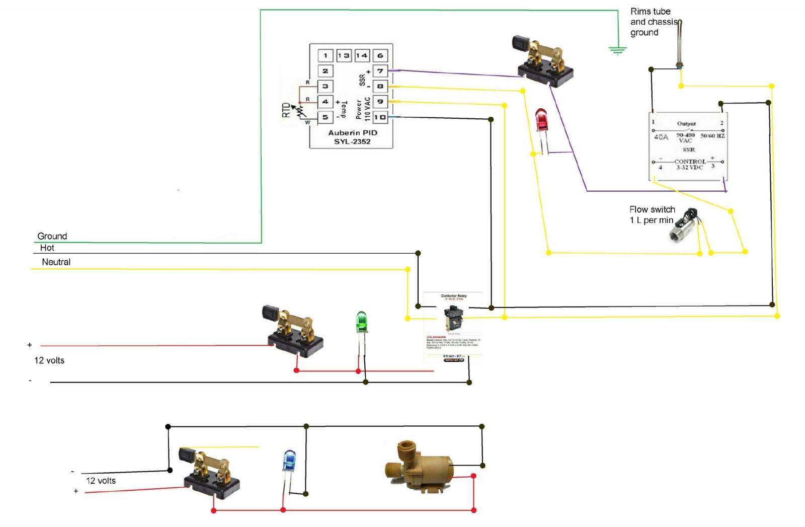
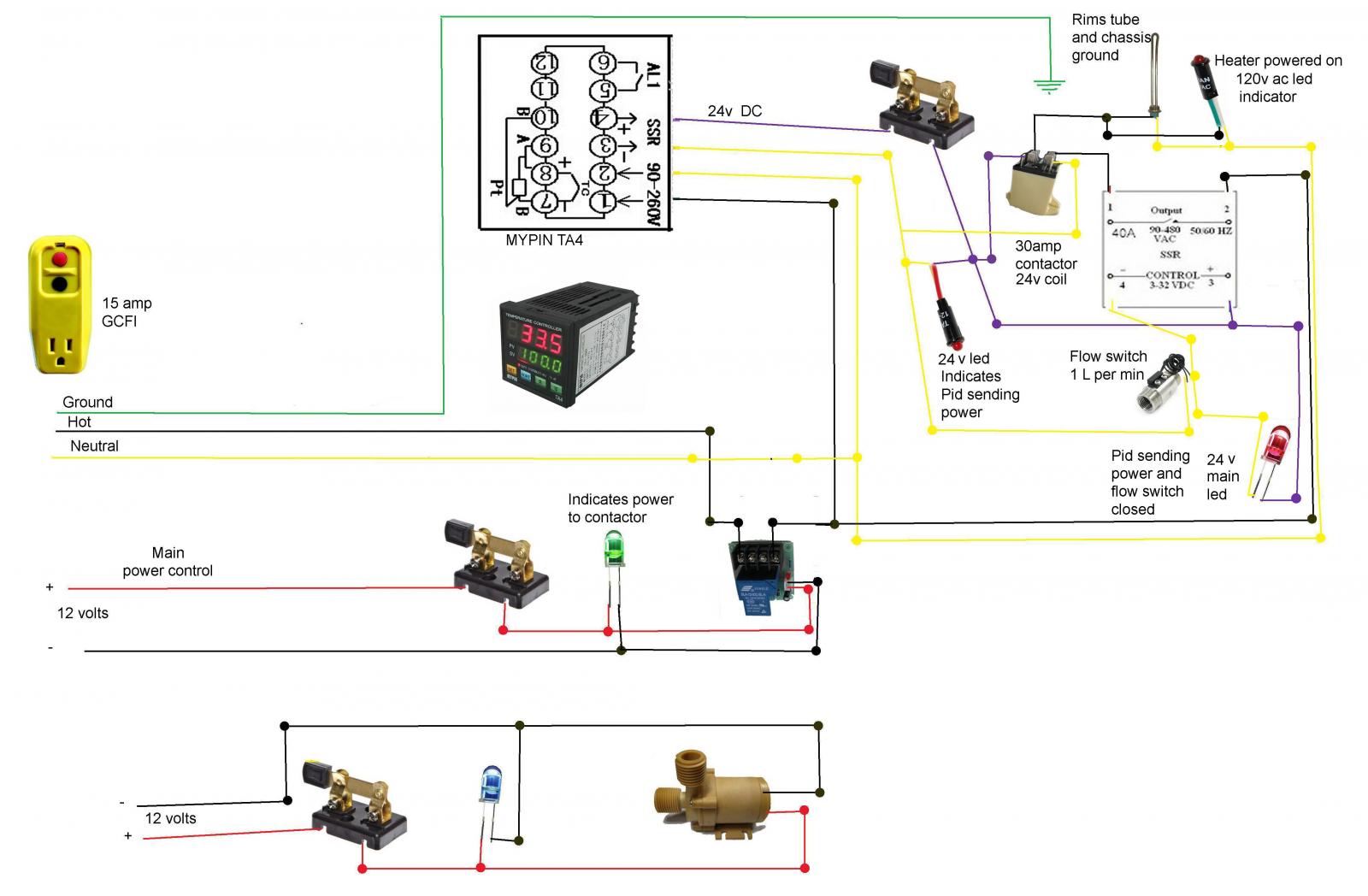
Can the electrical geniuses out there please check my work to make sure that I wont kill myself on my first e-BIAB day.

Shown LeD's are for illustration only I have 12v panel rated ones. (just couldnt find a good picture.) Diagram1.jpg

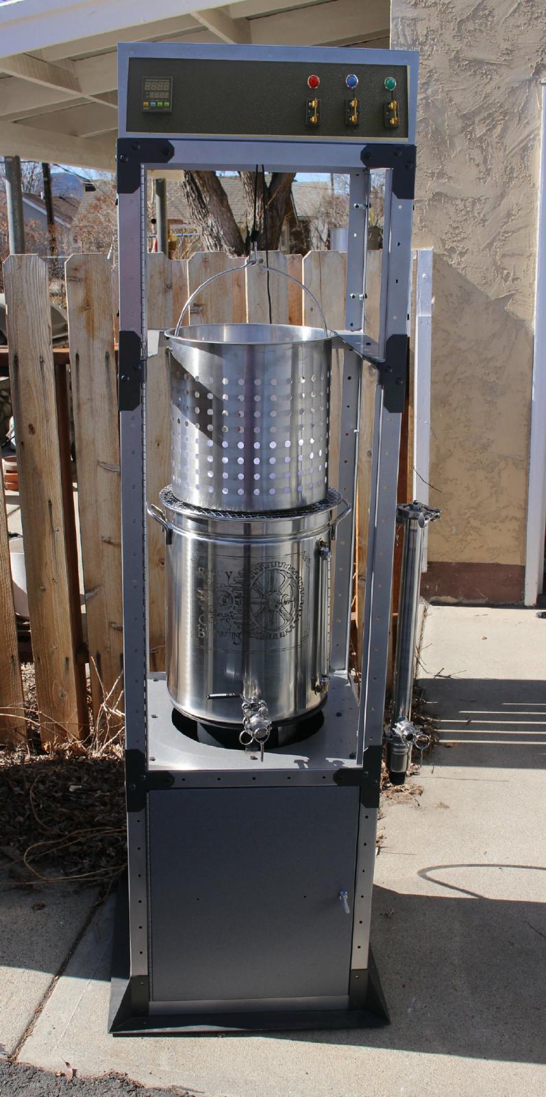
Using knife switches as an aesthetic, although they do add unnecessary complications.
_MG_0095.JPG
 
I'm a little confused with what you're trying to do here. You really only need one SSR for this setup, and you should have a switch between the SSR and the element. I wouldn't rely on an SSR to kill power to the element especially on the neutral side which is generally not used for switching. You should have a mechanical switch between the hot and the element. And most folks like a power switch as well, but I'm guessing you're using your GCFI for that?
 
I'm a little confused with what you're trying to do here. You really only need one SSR for this setup, and you should have a switch between the SSR and the element. I wouldn't rely on an SSR to kill power to the element especially on the neutral side which is generally not used for switching. You should have a mechanical switch between the hot and the element. And most folks like a power switch as well, but I'm guessing you're using your GCFI for that?

Agreed, the SSR on the left isn't a good idea. I think it would be better if it were replaced with a 12V coil, double pole contactor that would cut break both the hot and neutral lines immediately inside the panel.

@JINKS - That font may be good for labels (and you've done some nice work in that arena) but it just sucks on an electrical schematic. :smack:

Edit: The retro knife switches are cool, but kind of incongruous adjacent to a digital PID controller.

Brew on :mug:
 
I'm a little confused with what you're trying to do here. You really only need one SSR for this setup, and you should have a switch between the SSR and the element. I wouldn't rely on an SSR to kill power to the element especially on the neutral side which is generally not used for switching. You should have a mechanical switch between the hot and the element. And most folks like a power switch as well, but I'm guessing you're using your GCFI for that?


What I am trying to do is use the ssr as a power switch which allows me to power on the whole shebang with 12v knife switch rather than having 120 volts to the exposed switch.

I didn't put a switch between the ssr and the element because I don't want 120v at the panel on the exposed knife switches.

Hope this makes it clearer for what I am attempting and thank you for the help.
 
Agreed, the SSR on the left isn't a good idea. I think it would be better if it were replaced with a 12V coil, double pole contactor that would cut break both the hot and neutral lines immediately inside the panel.

@JINKS - That font may be good for labels (and you've done some nice work in that arena) but it just sucks on an electrical schematic. :smack:

Brew on :mug:

yea didn't change it in photoshop and would this work instead, because I can't seem to google up a 12v coil double pole contactor?

http://www.ebay.com/itm/30A-High-Cu...elay-Board-DC-Power-Control-new-/111288479921
 
Edit: The retro knife switches are cool, but kind of incongruous adjacent to a digital PID controller.

Brew on :mug:

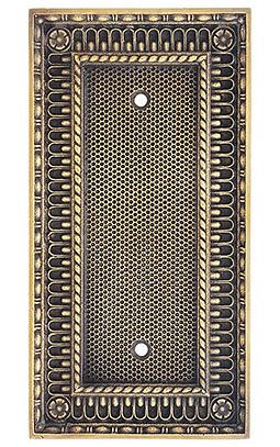
Yea gonna cover that with an 40 to 170 degree analog thermometer that I bought or this:

plate.JPG
 

That is a single pole relay, so it would work if put on the hot (120V) input wire rather than the neutral. The relay itself is rated for 30A, 250V thru the contacts, but looking at the circuit board design, I'm a little uncomfortable. Look at the third photo which shows the underside of the circuit board. The high current connections are implemented using something known as a thermal relief. These make soldering the components easier (which is why they are used), but the reduce the current handling capability of the connection. They may or may not be adequate for the ~11-12 amp load you will have. But if it were my panel, I don't think I would choose this relay.

Brew on :mug:

Cool, your the expert compared to me, I'll trust your judgement.
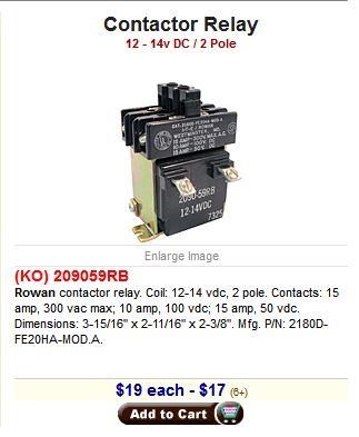
I did find this is it acceptable? Thanks again for your time

contactor.JPG
 
Revised with new contactor if it is acceptable.

Font changed to arial

url.jpg
 
Cool, your the expert compared to me, I'll trust your judgement.
I did find this is it acceptable? Thanks again for your time

That one will certainly work. I found a cheaper option here: http://www.ebay.com/itm/JQX-30F-2Z-...882?pt=LH_DefaultDomain_0&hash=item19d1577fc2. Although, it would require crimped connectors or soldered joints vs. the screw terminals on the one you show.

Edit: I went back and took a closer look at the thermal reliefs on the circuit board for the relay you originally proposed. I dragged some up some old work data from my memory banks, and am much more comfortable that this relay would work ok in your application. Since it is single pole, it should be placed in the 120V hot wire. There is really no need to switch the neutral wire (although it wouldn't hurt anything if you did.)

Brew on :mug:

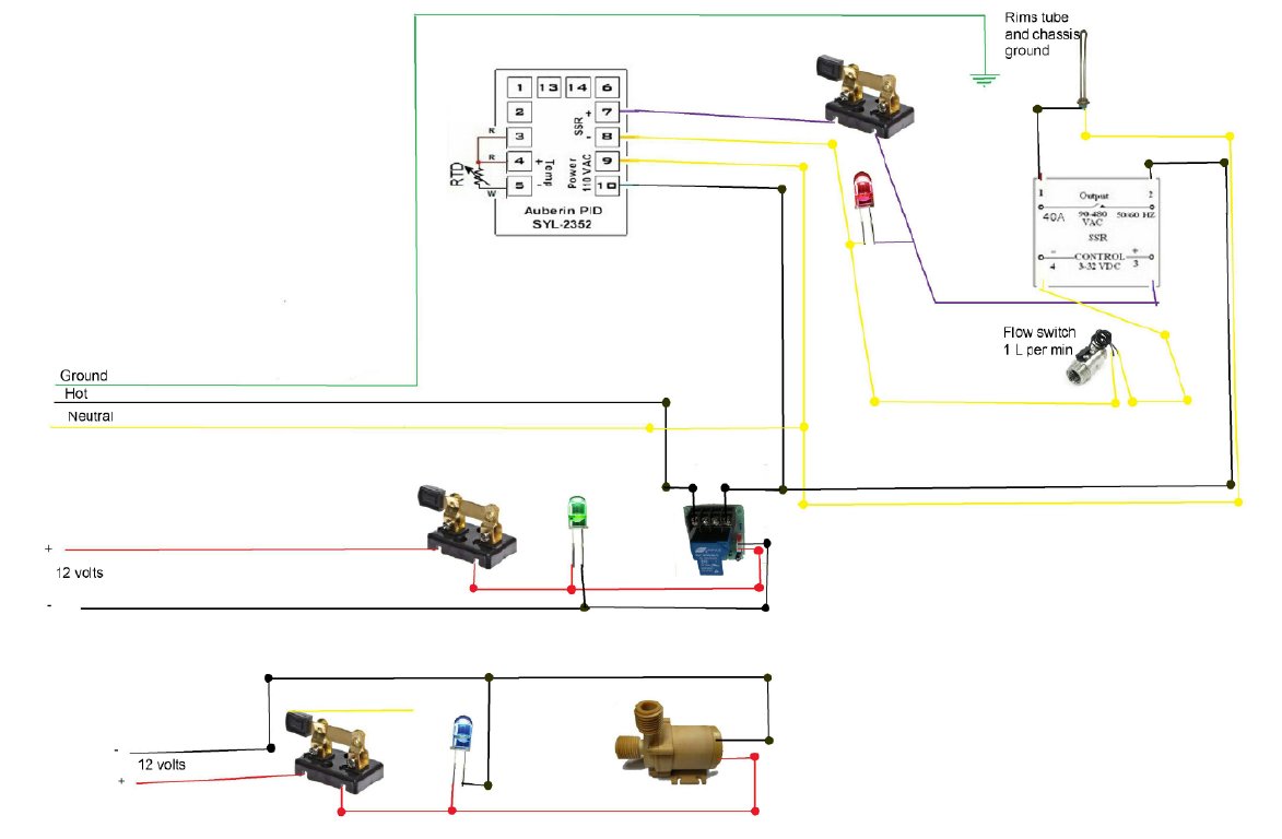
ok another revision with the original single pole contactor.

everything look ok with this or am I gonna die?:p

Diagram.jpg
 
Looks better! One more suggestion is to connect that red LED negative downstream of the flow switch so you'll know when it opens. I've never had as SSR fail but others have had several go out closed, so having that mechanical switch is a good idea. I see that you're trying to avoid 120 on the panel but consider having an indicator for when the element is powered. Doesn't have to be on the panel depending on how you house the element, but it'll let you know if there's power when it shouldn't be.

Edit: if you're already getting one contactor, why not get two and put it between the load on the SSR and element? Your panel looks big enough. And you can use the same switch you had on the PID out put.

Alright here is my attempt at an updated diagram.

I was playing around with the PID and discovered that the SSR output is 24volts dc. So now I run into a problem with the one red 12v indicator led.
I solved by putting a stepdown 24v to 12v circuit, but could I just add a large value resistor instead like 1M ohm or so?

Again thanks for your time
Diagram.jpg

P.S. I sure miss having a local Radio Shack. Now everything I need takes at least a week to get here.
 
ok another revision with the original single pole contactor.

everything look ok with this or am I gonna die?:p

You are gonna die, it's in your contract. But, this system is not likely to be the cause.

This circuit will do what you want. As @ChocolateMaltyBalls notes, if the SSR fails, you will still have power to the element even if the switch on the PID output is open. The switch controlling the contactor will always cut power to the element and PID when open.

Edit: Apparently it's tough to keep up with the pace of change on this thread. I see I got out of sequence.

Brew on :mug:
 
You are gonna die, it's in your contract. But, this system is not likely to be the cause.

This circuit will do what you want. As @ChocolateMaltyBalls notes, if the SSR fails, you will still have power to the element even if the switch on the PID output is open. The switch controlling the contactor will always cut power to the element and PID when open.

Brew on :mug:

Cool, thanks, its getting a little complicated appearing now.

Do you know if I can add a resistor to make the 12v led work on 24v or do I need the step down?

edit: disreguard question I found the exact same led's in 24 volt for cheaper than the step down.
 
Looks better! One more suggestion is to connect that red LED negative downstream of the flow switch so you'll know when it opens. I've never had as SSR fail but others have had several go out closed, so having that mechanical switch is a good idea. I see that you're trying to avoid 120 on the panel but consider having an indicator for when the element is powered. Doesn't have to be on the panel depending on how you house the element, but it'll let you know if there's power when it shouldn't be.

Edit: if you're already getting one contactor, why not get two and put it between the load on the SSR and element? Your panel looks big enough. And you can use the same switch you had on the PID out put.

You are gonna die, it's in your contract. But, this system is not likely to be the cause.

This circuit will do what you want. As @ChocolateMaltyBalls notes, if the SSR fails, you will still have power to the element even if the switch on the PID output is open. The switch controlling the contactor will always cut power to the element and PID when open.

Edit: Apparently it's tough to keep up with the pace of change on this thread. I see I got out of sequence.

Brew on :mug:


Ok hopefully the last time I need to bother you fine people
this is the final draft I hope.

Diagram.jpg
 
Cool, thanks, its getting a little complicated appearing now.

Do you know if I can add a resistor to make the 12v led work on 24v or do I need the step down?

edit: disreguard question I found the exact same led's in 24 volt for cheaper than the step down.

I think I would just leave out the LED that lets you know the flow switch is closed. It's not really telling you much now that you have the other two LED's. If the PID output LED is on, but the "element powered" LED is off, then the flow switch is open (or the second contactor failed, or the SSR has failed open [which is not the most common failure mode for SSR's])

Brew on :mug:

Yea I see your point, Thanks again
 
This is perfectly serviceable as it stands. I wouldn't bother with the contactor at all. There really is no reason not to switch the kind of load you are looking at directly. I would simply use the knife switch directly and eliminate the contactor. I personally feel you are making it significantly more complex than it needs to be.


I was disturbed by the first diagram where you were switching the neutral only....... a very dangerous practice. You don't need to switch the neutral at all, and NEVER switch only the neutral.


H.W.

I would never recommend switching line voltage with an open knife switch. It's a big shock hazard.

Good call on not switching just the neutral. I think that reasoning played a part in the first responses to OP, but it was not explicitly stated.

Brew on :mug:
 
Even if those knife switches are rated for the current, I would still use the contactors. I think the OP has been trying from the first post to ensure that those switches were safe.

This might be nit picking but consider dropping the PID out indicator, I think the mypins have an out indicator and you also have the flow switch indicator. Seems a bit redundant, but hey this is your build so you should feel free to do whatever you please (like using knife switches). It looks safe enough to me. I hope you enjoy building and using your system, it's a lot of fun.

Yes I want to use the knife switches and absolutely want them safe that is why all the extra hoopla to make them low voltage and low current.

I agree on to many led indicators. I plan on keeping the one after the flow switch and the one mounted in the rims tube.
 
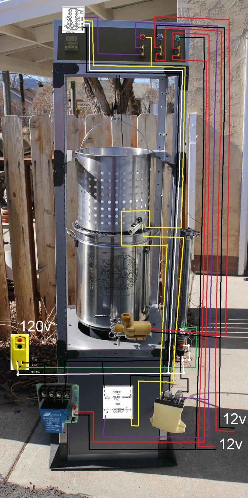
The problem now is that I wanted to only have the things on the panel be at the top and all the other contactors, ssr, etc hidden in the cabinet located at the bottom. I managed to get myself lost on how many wires are running up and down the sides. Planning on buying multistranded wire except for the 120v which would be 15 amp rated. I may end up just putting everything at the top for simplicity, as I have made it complicated enough.

07 copy.jpg
 
I would never recommend switching line voltage with an open knife switch. It's a big shock hazard.

Good call on not switching just the neutral. I think that reasoning played a part in the first responses to OP, but it was not explicitly stated.

Brew on :mug:

I mistakenly assumed that these were closed knife switches..... that the images in the circuit diagram were representative of knife switches, but not necessary OPEN knife switches. I didn't look at the photo, so I obviously was very much in error. I was focusing on schematics.

The conactor is handling 10.8 amps......... Not a heavy load. This is a 120 volt circuit, so the 5500 watt rating is irrelevant. There are ordinary switches like light switches that will handle 20 amps easily, so it makes little sense to use contactors and a low voltage circuit. Just more complexity and more cost for no benefit........ Purely a matter of styling. Clearly if open switches are desired, a low voltage circuit and relays or contactors are necessary. Each person's sense of "style" is different. I would be inclined in this case to use lighted "push on / push off" buttons in this case. It's worth noting also that a significant amount of resistance is needed to run normal LEDs on 12 volts. The local Carquest store has some very nice little panel lights that are inexpensive and run on 12 volts. Just drill a hole and push them into the hole and they snap into place. They are available in red, yellow, and green.


H.W.
 
Glad to be of service. Now that I am retired, I need something technical to keep my mind active.

Brew on :mug:

Even if those knife switches are rated for the current, I would still use the contactors. I think the OP has been trying from the first post to ensure that those switches were safe.

This might be nit picking but consider dropping the PID out indicator, I think the mypins have an out indicator and you also have the flow switch indicator. Seems a bit redundant, but hey this is your build so you should feel free to do whatever you please (like using knife switches). It looks safe enough to me. I hope you enjoy building and using your system, it's a lot of fun.

What do you folks think? completely ridiculous? It looks like I could get it done with an 8 strand wire plus a 15a rated ac power cord and a extra wire or 2 to the halfway point.

The red spot on the rims tube is a horrible representation of a 120vac led.

Paneltry.jpg
 
I mistakenly assumed that these were closed knife switches..... that the images in the circuit diagram were representative of knife switches, but not necessary OPEN knife switches. I didn't look at the photo, so I obviously was very much in error. I was focusing on schematics.

The conactor is handling 10.8 amps......... Not a heavy load. This is a 120 volt circuit, so the 5500 watt rating is irrelevant. There are ordinary switches like light switches that will handle 20 amps easily, so it makes little sense to use contactors and a low voltage circuit. Just more complexity and more cost for no benefit........ Purely a matter of styling. Clearly if open switches are desired, a low voltage circuit and relays or contactors are necessary. Each person's sense of "style" is different. I would be inclined in this case to use lighted "push on / push off" buttons in this case. It's worth noting also that a significant amount of resistance is needed to run normal LEDs on 12 volts. The local Carquest store has some very nice little panel lights that are inexpensive and run on 12 volts. Just drill a hole and push them into the hole and they snap into place. They are available in red, yellow, and green.


H.W.

Yea I gotta make it difficult because I want to make it semi-victorian/steampunk appearing. Plus knife switches bring back cool childhood memories of Young Frankenstein.
 
What are the dimensions of the top panel? From the way it looks in the pic it should be plenty big enough to fit all the internal components. Probably better off putting all the guts in the top and running down a few wires to the element, pump, and flow switch. If that frame is hollow you can use it as a conduit to hide and protect the wiring.

Edit: what is that thing? A server rack or some kind of incubator?

17" wide by 4" tall by 1/4 thick abs plastic.
I would prefer not to put a bunch of holes through it, so is it safe to epoxy a board to the back and screw the components to that?

And it is a discarded sunglasses display here is the build thread if your interested.
https://www.homebrewtalk.com/f253/sunglasses-e-biab-519664/
 
Nice find. You can attach something like a piece of scrap wood to the inside top to use as a mounting plate.

You should also consider some kind of shielding to keep condensation from the boil away from the electronics.
 
Nice find. You can attach something like a piece of scrap wood to the inside top to use as a mounting plate.

You should also consider some kind of shielding to keep condensation from the boil away from the electronics.

Great I'll use some scrap plywood I have sitting around.
Part B: I agree on the condensation still running solutions for it around in my head.
 
Make certain you're applying PID power to the correct pins. I see you're showing the Aubur 2352 in the diagram which does need ac power on 9 & 10, but the Mypid diagram I checked shows 1&2. Also, if anyone uses the Auber 2362, note the power input is also pins 1&2, not 9&10. I can confirm unfortunately the PID doesn't like ac power on the RTD inputs.
 
I vote for all the electronics above the BK (with protection from condensation.) It's generally a bad design practice to have electronics below a liquid container. Spills happen, ya know. Also, don't you have a propane burner in the base? I wouldn't want my electronics anywhere near that environment.

Brew on :mug:

Yep I'm gonna have to put them up top.
 
Back
Top