RIMS Control Panel Review/Help

Homebrew Talk - Beer, Wine, Mead, & Cider Brewing Discussion Forum

Help Support Homebrew Talk - Beer, Wine, Mead, & Cider Brewing Discussion Forum:

This site may earn a commission from merchant affiliate links, including eBay, Amazon, and others.

Glock

Member
Joined
Sep 18, 2013
Messages
24
Reaction score
0
Hello All,
Been stalking this forum for nearly 3 years since I began brewing and it's been a great help. I now need to make my first post.

I’m almost done creating a 2-tier system with one pump, a RIMS tube, and BK operated by propane. However I need help creating the brain. I got a ton of information from the numerous wiring diagrams and thought I had mine nailed down but got stumped on the light-up push button switches I decided to purchase

Basically I'm trying to have one switch allow power to the rest of the elements in the panel. The RIMS tube will be used to maintain mash temp and I have a single pump that I'll need to run independently for transfer. I added a switch for the PID just because. I’m mostly getting confused on the neutral returns to the lights. But I have many other questions that will put my mind at ease if I did it correctly.

So my question is if my wiring diagram is correct?
Am I using the right kind of switches?
Will the Main Power Switch illuminate once closed without any other switch closed?
Does PID wiring look correct to power the RIMS tube outlet element on/off when needed?
Are fuses in right spot/right kind?
Will E-Stop trip GFCI?
Any other glaring problems with the diagram?

I hope I explained what I’m trying to do well enough. Thanks for the help.
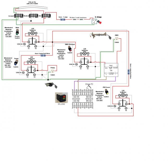
RIMS Control Panel.jpg
 
It's a little small, but I get the point - 120Vac RIMS heater? It works for me I guess.

You're utilizing your GFCI as an E-Stop? I suppose that would work but that's not how I'd do it - I'd cut the control power to the pump and the PID or between the PID and SSR. They also make these cool shunt operated circuit breakers that would disconnect when they loose power - I'd do something like that instead of tripping the GFCI. (My e-stop is to unplug the whole unit...)

The switch to cycle power on the PID controller is overkill in my opinion - your opinion may vary...

I've got one of these on mine - which is a similar system to yours and really like it. It shows the status of your element in amps - mine runs about 12.4 amps while its on - if it get a lot less or more, I'll replace the element.

http://www.ebay.com/itm/Digital-Blu...957?pt=LH_DefaultDomain_0&hash=item35c78e79c5

I'm using an Omron E5CS PID controller - so I'm unsure if your wiring is correct there.
 
@ atoughram, Thanks for your reply. You're right the PID switch is overkill, I was thinking I might as well have it since I'm already spending enough money on the other switches that what would be one more. My cheapness set in though and you talked me out of that part of it. I thank you. The E-Stop is there just because if something does happen and I can't get to whatever switch and someone else can, then they can just trip the outlet by hitting one button. Doubt it would ever be needed. I seen that E-brewery used a shunt in their panel but I figured something this small wouldn't need one. I like the amp reader idea, but I think that may have to be a future upgrade. I'll have this on a dedicated breaker/circuit, so hopefully my draw isn't over 80%, nor should it be. Thanks again for your reply.
 
@ P-J, I was hoping you would see my post, I've been studying your diagrams for a while and they are a huge help. That's what I used as reference for mine, however I don't know why the size got so shrunking down after posting it. Sorry about that. The reason I posted the diagram was because I couldn't find any of yours that would work for my system, but wouldn't you know it I found one on here yesterday. (seriously I furiously searched for one for my application) Too funny. Anyway...

This is the exact one I'm going with

http://www.pjmuth.org/beerstuff/images/Auberin-wiring1-SYL-2352-basic5-RIMS.jpg

Except I'll be using a SYL-2362 and my heating element is a LWD 4500@240, obviously wired for 110.

I like that the RIMS tube won't run unless the pump is on, but can be run independently, which I need. And also the light on the element telling you when it is on is cool and telling about how much heat is being lost in the mash tun and so forth.

I do have a couple of questions about it though.

Why do the switches have to be 2NO? I was going to go with 1NO 1NC, but seen you had this diagram using the 2NO.

Also can I use 12 gauge wire for everything? Including the PID/SSR control?

I was also planning on using this type of box to house eveything http://www.menards.com/main/electrical/rough-electrical/junction-boxes/new-work/10x10x4-screw-cover-pull-box/p-1408845-c-6429.htm

Do you see any problems there? Like maybe not being deep enough.

P-J thanks so much for your help on these forums, your work and time are greatly appreciated.

I can't wait to get me rig up and running with the pump and tube. I've used it in analog mode and keep telling myself more automation will be better, and I sure hope it is. I'll be sure to post pictures and hopefully explain what I made to help out any so called noobs. I was one and hopefully I'm far enough along in my brewing that I can help out others.

Thanks again!
 
12ga wire on the power wiring for the element is a good idea. 14ga or less for the pump would be OK, my pump only draws 1.2 amps. 10X10X4 box should work fine, mine is a 10X10X5 and it has plenty of room.

You don't need the two N.O. contacts on the switch, on 120V circuits you shouldn't have to break the neutral, just the hot wire. (120V Neutral is tied to the ground bus in your breaker panel). On 240V circuits both the black and white wires are hot so its a good idea to switch both, whereas in 120V circuits only the black wire is hot. You could use the other N.O. contact on the pump switch to open the SSR control circuit, shutting off the elements whenever the pump isn't running and wire the neural around the switch.
 
That makes sense with the 2NO switches, I wasn't thinking 240V 2 hots since I'm going 120V to start. I think I'll go with the 2NO incase of a future upgrade to 240V. Time to get over to auber to get my order in. It's so nice that this is the last (major) purchase for this system.

I was just asking about the 12ga wire since that's how I'll be bringing the power in and thought might as well use it to wire up everyone else. I thought you could go as low as 22ga running to control on the SSR, but figured if I have 12ga, then why not use 12 ga. Thought I'd put that question out there incase there was some reason against using 12ga for control.

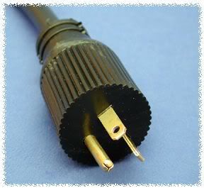
Here's another question. I haven't found one of these and don't even know if they make them. But do they make a 3-prong cord that looks more like a dryer plug? One that would have hot, neutral, and ground? I know I don't need one since a regular 120v can be used, but thought it would be neat to have. Also that way you can't plug the element and pump into the wrong spots in the panel, which is going to be removable from my rig.

Thanks again for the help
 
you could use a 120V 20a plug on the element like this
20A-5-20P.jpg


and make sure that the outlet for the pump is only a 15a unit like this
dadoes++12-17-2012-10-52-3.jpg
 
Nice! I was looking for more of the dryer type plug, but it's a great call on the straight blade plug for the element and 15amp plug for the pump. I think that it will look a lot cleaner to in the panel. That's exactly what I'm going to do. Thanks again
 
A 2000W element on 120V draws 16.7 amps. 20A protection is appropriate.

Oh - and your last question. Fast blow fuses are appropriate for our application as we are dealing with resistive loads.

Thank you, fast blow fuses all around, check.

I think another problem has arisen. I'm running this on a dedicated 20 amp breaker however I planned on using a 4500W 240v LWD element. Even if I'm running it on 120v does that mean my draw is 18.75 amps? Or 4500W/120V = 37.5? or... since wattage is knocked down by 1/4 is it 1125w/120v = 9.375 amps. In other words I'm confused and concerned that the element will trip the breaker. Thoughts?

Thanks

Yes.. You got it right with this:

"since wattage is knocked down by 1/4 is it 1125w/120v = 9.375 amps"

Right on the money!!!

P-J
 
Awesome Sauce!! Thanks again P-J

Glad I don't have to return another element (first one was HWD) and I don't have to get different fuses since I questioned myself after getting fast-blow fuses then noticed that the diagram didn't say "fast-blow". So I think I'm good to start my build...but now that I've said that I'm sure something will come up and have to ask. Thanks again P-J you rock!

I'm really glad that I could help you. When you have other questions for me with your build - just post them on this thread as I've already involves with you. This is a suggestion as I have my PMs turned off [because I got tired of the hundreds of questions via pm's to me every month].

I'll help you as best that I can.

P-J
 
So I finally got my RIMS tube back from the plumber's shop. Basic setup but made out of copper. I got everything hooked up and starting running a test. I had the water flowing through the pump and tube but when I turn on the RIMs tube switch it trips the GFCI. The panel is wired right, I'm able to plug in something else (ie hair dryer) and the outlet works, although it doesn't run continous it's a second on, second off. The element is grounded by 12-3 wire with the ground attached the the tube via hose clamp. So my question is why does the tube keep tripping the element. Is....?

the element touching the side of the tube?
the load too much for the extension cord? (was using 14-3)
 
or is JB Weld conductive? Is so then that could be the problem.
 
Ok, so in trying to eliminate the problem I finally just filled the RIMS tube with water and plugged it straight into the GFCI outlet I plan on using for the brew rig. Not the smartest idea I know but I was at a loss for trying to determine the problem. So with the tube plugged in and the GFCI tripped I tried to reset the GFCI outlet but I would just trip again upon release of the button. The wire connections are dry, the ground wire is attached via hose clamp around the tube, so what's the problem here? Would the heating element touching the inside of the RIMS tube cause the GFCI to trip?
 
Would the heating element touching the inside of the RIMS tube cause the GFCI to trip?


No. Water is conductive so having water touch the heating element would have the same affect as the element touching the side of the tube.

You really need to buy yourself a multimeter if you don't already own one. Use it to measure the resistance between the different wires. You should measure 10-20 Ohms between hot and neutral. You should measure an open between either of them and ground. Sounds like you have a short between one of them and ground. Start disassembling the RIMS tube to see what's causing the short.

You should always use a multimeter to ohms things out before you plug anything in.
 
He's not pulling anywhere near 20amps but that doesn't trip a GFCI anyway.

Did you say you potted the electrical with JB weld? That makes it hard to troubleshoot.

The JB Weld is now removed. I took apart the whole tube to try and diagnose the problem by starting at the beginning. Still had the same problem so back at it today.
 
Ohms read 13.8 when connected to hot and neutral. No reading or actually 1 when hot to ground or neutral to ground. The panel reading is 230 with all the switches closed. Thoughts?
 
Ohms read 13.8 when connected to hot and neutral. No reading or actually 1 when hot to ground or neutral to ground. The panel reading is 230 with all the switches closed. Thoughts?

Sorry but what do you mean by "or actually 1"?
 
Sorry but what do you mean by "or actually 1"?

Sorry it doesn't say 1 it's the default symbol "|" when the meter is turned on. So there is no reading when hot or neutral to ground
 
Sorry it doesn't say 1 it's the default symbol "|" when the meter is turned on. So there is no reading when hot or neutral to ground

ahhhh, open circuit.
All I can think of is a stray wire and when you removed the JB weld it moved the wire. Is it still tripping the GFCI?
 
ahhhh, open circuit.
All I can think of is a stray wire and when you removed the JB weld it moved the wire. Is it still tripping the GFCI?

Yes after JB Weld was removed I tried it again and it still tripped the GFCI. At this point I may have to get a new wire for the element or a new element itself. I'm at a loss here since all the the visual wiring seems intact.
 
ahhhh, open circuit.
All I can think of is a stray wire and when you removed the JB weld it moved the wire. Is it still tripping the GFCI?

I'm confused now (or have been) Don't I want the reading to be open between the hot/neutral to the ground. Otherwise it would mean current would be flowing through the ground causing the trip?
 
I'm confused now (or have been) Don't I want the reading to be open between the hot/neutral to the ground. Otherwise it would mean current would be flowing through the ground causing the trip?

Sorry if I confused - yes you are right you want no continuity between hot/neutral and ground.
What I meant was maybe you had a stray wire (as in one strand of the wire not the whole thing) touching ground that you missed.
Another thing to check is making sure you don't have any transposed nuetral/ground by accident - either in the panel, although I don't expect it since you say a hairdryer works ok, or in the cord going to the RIMS element - i.e. Check the point-point continuity from the plug to the terminal screws/ground on the element and make sure the hot/neutral/ground are where you think they are.
 
Check the point-point continuity from the plug to the terminal screws/ground on the element and make sure the hot/neutral/ground are where you think they are.

That is the next plan when I get home. I should get a reading of 0.9 on all of those. I already opened up the plug to make sure the wires were to the right screws but double checking isn't a bad thing. Also going to open the panel and make sure the ground hasn't come loose from the outlet to the terminal bar. After that the plan is to fill the tube with water and plug the panel into a different GFCI outlet, just to see if there is any difference. I feel that I have a grounding issue or a bad element.

Actually check that, I know the panel is fine. I have no idea if it would help but I'm almost ready to drive a earth grounding rod into the frozen tundra and connect a ground wire to that from the tube to see if it would make a difference
 
I changed nothing. I simply filled the tube with water plugged it into the panel and allowed it to heat. No trip, no problem. Well i shouldn't say no problem the K TC hooked up to the SYL-2362 hasn't noticed the temperature increase, I'll have to research how to calibrate the PID
 
Looks like the wiring of the probe for the thermocouple is bad. I wiggled the wire a little where it enters the panel and the temperature shot up to 140 which is what the dial thermometer read. I'm guessing the PID was reading the ambient temperature of the room that's why it was allowing the element to heat. So basically a potentially dangerous situation, so time to get the thermocouple wiring fixed.
 
Back
Top