When I built my system, I wanted to have a lamp on the panel than would light up when there was current flowing through my heater element. I bought some 120v lamps for this.
Here's how it was connected right after installation in the in-progress panel. Red and black come through contactor. Red line is then switched by SSR and feeds lamp and heater element (heater element not plugged in at this time). Black line goes right from contactor to element. Lamp was connected to the switched 120V hot line and neutral.
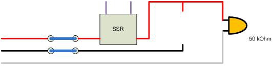
After hooking it up, I flipped on the contactor. SSR was not even connected to the PID at this time. To my confusion, the lamp illuminated. Eventually I realized that this made sense. The SSR leaks a little current, and the lamp needs very little current to illuminate, so the leaked current was taking it's only route available and was coming through the lamp to neutral.
So, I think, "Well... when I have a much lower resistance path available for that leaked current to go travel through, then it should work." So, I plugged in the heater element. The SSR is still not connected to the PID, but it now looks like this:

When I turn on the contactor, the lamp still lights up.
THAT'S QUESTION #1: why is the little bit of current that leaks through the SSR going through the lamp instead of going through the much lower resistance heater element?
Screw it. I am using the system. I used it like this for a year. The lamp comes on as soon as I activated the contactor, and stays on, fully illuminated, no matter what. PID might be driving SSR, might not, but the lamp is on. Period. The only way to shut the lamp off is to turn off the contactor.
I've been adding things to my panel and tweaking stuff recently. I decided to fix this thing. I got rid of the neutral and connected the lamp fully in parallel to the heater element. With a resistor added to match the lamp so that 120V drops across the lamp and 120V drops across the resistor. This DOES behave in a sane way, but just wait for more insanity.
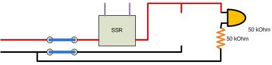
In this configuration above, the lamp is partly lit when the contactor is on and the heater element is not plugged in and the SSR is not being triggered. This makes sense because of the leakage current from the SSR. When the SSR is triggered, the lamp lights up fully. This all makes total sense.
So, plug the heater element in now:

Everything SEEMS to be functioning perfectly. With the heater plugged in, leakage current from the SSR goes through the element and not the lamp, and the lamp stays dark. When the SSR is triggered and the heater starts to fire, then the lamp comes on fully. Perfect and exactly what I wanted.
Happy with the fact that it seemed to be working, I shut everything off and turned out the lights in the garage.
Wait... What's that!? The lamp is on just BARELY. Hard to see with overhead lights on, but obvious when the garage is dark.
So... this is the REAL confusing part to me.
Why is the lamp on at all when I have this:

The black hot line to the lamp is alive because it's coming from a point prior to the contactor, but the red hot line is DEAD. The contactor is off. There can't be any leakage through the SSR, because there is no source attached to the SSR.
Here's how it was connected right after installation in the in-progress panel. Red and black come through contactor. Red line is then switched by SSR and feeds lamp and heater element (heater element not plugged in at this time). Black line goes right from contactor to element. Lamp was connected to the switched 120V hot line and neutral.
After hooking it up, I flipped on the contactor. SSR was not even connected to the PID at this time. To my confusion, the lamp illuminated. Eventually I realized that this made sense. The SSR leaks a little current, and the lamp needs very little current to illuminate, so the leaked current was taking it's only route available and was coming through the lamp to neutral.
So, I think, "Well... when I have a much lower resistance path available for that leaked current to go travel through, then it should work." So, I plugged in the heater element. The SSR is still not connected to the PID, but it now looks like this:
When I turn on the contactor, the lamp still lights up.
THAT'S QUESTION #1: why is the little bit of current that leaks through the SSR going through the lamp instead of going through the much lower resistance heater element?
Screw it. I am using the system. I used it like this for a year. The lamp comes on as soon as I activated the contactor, and stays on, fully illuminated, no matter what. PID might be driving SSR, might not, but the lamp is on. Period. The only way to shut the lamp off is to turn off the contactor.
I've been adding things to my panel and tweaking stuff recently. I decided to fix this thing. I got rid of the neutral and connected the lamp fully in parallel to the heater element. With a resistor added to match the lamp so that 120V drops across the lamp and 120V drops across the resistor. This DOES behave in a sane way, but just wait for more insanity.
In this configuration above, the lamp is partly lit when the contactor is on and the heater element is not plugged in and the SSR is not being triggered. This makes sense because of the leakage current from the SSR. When the SSR is triggered, the lamp lights up fully. This all makes total sense.
So, plug the heater element in now:
Everything SEEMS to be functioning perfectly. With the heater plugged in, leakage current from the SSR goes through the element and not the lamp, and the lamp stays dark. When the SSR is triggered and the heater starts to fire, then the lamp comes on fully. Perfect and exactly what I wanted.
Happy with the fact that it seemed to be working, I shut everything off and turned out the lights in the garage.
Wait... What's that!? The lamp is on just BARELY. Hard to see with overhead lights on, but obvious when the garage is dark.
So... this is the REAL confusing part to me.
Why is the lamp on at all when I have this:
The black hot line to the lamp is alive because it's coming from a point prior to the contactor, but the red hot line is DEAD. The contactor is off. There can't be any leakage through the SSR, because there is no source attached to the SSR.