Electric brewery plans - need help

Homebrew Talk - Beer, Wine, Mead, & Cider Brewing Discussion Forum

Help Support Homebrew Talk - Beer, Wine, Mead, & Cider Brewing Discussion Forum:

This site may earn a commission from merchant affiliate links, including eBay, Amazon, and others.
Tiber_Brew,

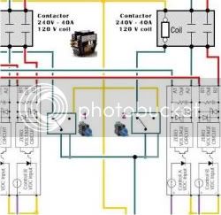
Ok... It took a little while with the bits and pieces - but - Here is latest diagram. It has the breakers that you ordered and I've also placed pix of your switched. I've changes some of the foot notes as well.


As usual - Click on the image for a full scale drawing.
The full sacle image is set up for printing on a 11" X 17" sheet of paper.

I sure hope this helps you. Please let me know your thoughts.

That looks great, P-J. Nice work!

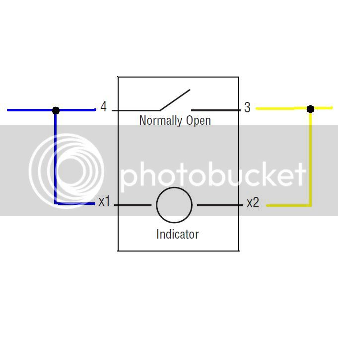
I do have one question about those switches, though. I looked at the datasheet for them and I'm still a little unclear about how to wire them with the indicator. The LED bulb takes the full 120V, so would I just split a line into the X1 and a neutral to the X2?

I tried showing this on your diagram (with my mad MS Paint skills). Take a look at switches 1 & 2. Does that look correct to you?

wiring5500wIVillumswch-2.jpg


Here are my MS Paint skills again. The blue is hot, yellow is neutral.

illuminatedwiring.jpg


Thanks again. I appreciate all the great help I'm getting here.

TB
 
50A is easy to find. That's what electric stoves plug into. Shouldn't cost any more than 30A stuff either.

I use "NEMA 14-50" plugs and receptacles, bought them at Home Depot (or Lowe's... I can't remember).


edit: fyi, 4-wire dryer plugs and receptacles are "NEMA 14-30". the "14" is the style of plug and the "30" is the amp rating.

Nema 14-30 and 14-50 look similar. The difference is that the 30A one has one of the prongs on the plug shaped like an "L" while the 50A is shaped like an "l". This is done to prevent you from plugging the wrong thing in.

Ah, I see. Thanks, Walker. That makes sense now. Did you use 30A receptacles and plugs for your elements and 50A for the main power from service?

TibermakesatriptoLowesBrew
 
Update: more parts are in now.

Got the enclosure and the heat sinks. Shown here accompanied by a glass of Move Overon. (Recipe here.)

IMG_4799.jpg


IMG_4801.jpg


IMG_4800.jpg


A little TLC, some sanding, priming, painting and vinyl graphics, and this will turn out to be at the very least good enough for who it's for.

TB
 
Looks great! Can't wait to see how it turns out...I'm definately stealing the wiring diagram :mug:

Please keep us updated on the build.

Anyway of providing a detailed list of all the parts and where they have been ordered?

Thanks for the help!
 
Looks great! Can't wait to see how it turns out...I'm definately stealing the wiring diagram :mug:

Please keep us updated on the build.

Anyway of providing a detailed list of all the parts and where they have been ordered?

Thanks for the help!

Absolutely! I plan on posting an updated parts list with costs along with pictures of my progress.

I owe a great deal of my progress to the HBT community, so I'll give back what I can.

TiberpayitforwardBrew
 
Great!

I was planning on adding a digital thermometer for monitoring the mash in the MLT alongside the control panel...how are you going about your MLT temp?
 
Tiber_Brew,

Ok... I have added the wiring for the switch lighting. I also changed the annotation for the mains power to be a 50 amp mains GFCI breaker. The system power consumption is close but I really believe it will be A-Ok with that. Plus you will have a much easier time finding the cord and outlet for that. (Range outlet and cord - It MUST be a 4 wire cord.) If this gives you any problem - just change one of the elements to a 4500 W element and you will be just fine. I've changes some of the foot notes as well.


I've updated the drawings under the same name so you need to refresh your browser when you read this message and also when you click on the link for the large image. My last post will show the same image when refreshed as well.

As usual - Click on the image for a full scale drawing.
The full sacle image is set up for printing on a 11" X 17" sheet of paper.

I hope this helps you and I really wish we could have talked some of this out.

Please let me know if this is ok now.

Edit: If you looked at the pix within the 1/2 hour - please refresh the image. I screwed up on one of the image placements.
I know. I'm fastidious.
It's fixed now.
 
Great!

I was planning on adding a digital thermometer for monitoring the mash in the MLT alongside the control panel...how are you going about your MLT temp?

Since I single infusion mash in a 10 gal cooler, I've got a digital oven thermometer on a 3' cord that I use. I put the probe in the mash and set the display unit on top of the tun. Low-tech, but works like a charm. No thermowells sticking out on the inside to bump with my mash paddle, and no drilling holes in the cooler. Who knows, I may upgrade to something higher tech later.

I frequently do decoction mashing for my lagers, but the digital thermometer works well for that, too.

TB
 
Tiber_Brew,

Ok... I have added the wiring for the switch lighting. I also changed the annotation for the mains power to be a 50 amp mains GFCI breaker. The system power consumption is close but I really believe it will be A-Ok with that. Plus you will have a much easier time finding the cord and outlet for that. (Range outlet and cord - It MUST be a 4 wire cord.) If this gives you any problem - just change one of the elements to a 4500 W element and you will be just fine. I've changes some of the foot notes as well.

That looks great, P-J! That's what I had in mind about wiring the switches, but I'm glad to see that's the way you'd do it as well. Thanks a ton for drawing this again.

I hope this helps you and I really wish we could have talked some of this out.
I thought that's what we were doing? :mug:

I know it'd be a lot easier in person. Wish we could work it out face to face with a sketch pad or something. I think you've done a fantastic job though, and appreciate what you're doing for me!

Please let me know if this is ok now.

Edit: If you looked at the pix within the 1/2 hour - please refresh the image. I screwed up on one of the image placements.
I know. I'm fastidious.
It's fixed now.

Again, looks great! I'm going to use this one.

I think I'm going use single dedicated outlets for each of the pumps. Such as this one:

single%20220v%20receptacle.jpg


Thanks!
TB
 
Welcome.

You might consider using a duplex outlet. It might make your life a little easier.

duplex-outlet.jpg


The arrows point to a small break away tab. Just snap off the one on the left side (brass terminal screws). This way you will eliminate some wiring complexity as the neutral and ground will be common for both outlets.

You would only need to cut one hole in the box as well.
 
How would the wiring diagram change if I were to directly connect the elements and pumps rather than using outlets...

Thanks
 
I love it when its that simple!

Sorry for hijacking the thread once again...but:

I've got two 4500W elements in the HLT...how would that change the wiring diagram?

Thanks gurus
 
How would the wiring diagram change if I were to directly connect the elements and pumps rather than using outlets...
The wiring would not change except for the elimination of the physical plugs and outlets.

However, I think that it would be a huge mistake to do that especially in reference to the heating elements. Doing so will prevent you from removing the kettles for cleanup and put you at risk if you don't disconnect your entire system during cleanup.
 
I love it when its that simple!

Sorry for hijacking the thread once again...but:

I've got two 4500W elements in the HLT...how would that change the wiring diagram?

Thanks gurus
The only change would be that you 'could' use 20 amp 240V breakers instead of 25 amp.
 
Welcome.

You might consider using a duplex outlet. It might make your life a little easier.

duplex-outlet.jpg


The arrows point to a small break away tab. Just snap off the one on the left side (brass terminal screws). This way you will eliminate some wiring complexity as the neutral and ground will be common for both outlets.

You would only need to cut one hole in the box as well.

Ahh, I didn't know that tab could be broke off! Nice. I will definitely go that route. Thanks once again!

More updates soon.
TB
 
Ahh, I didn't know that tab could be broke off! Nice. I will definitely go that route. Thanks once again!
If you want to get sneaky about mounting the outlet, use a standard outlet cover plate as a template and scribe the 2 ports for the outlets. Cut out the 2 ports and then drill the hole for the center screw. After you complete the wiring, Simply mount the outlet to your control box using the center screw.
 
If you want to get sneaky about mounting the outlet, use a standard outlet cover plate as a template and scribe the 2 ports for the outlets. Cut out the 2 ports and then drill the hole for the center screw. After you complete the wiring, Simply mount the outlet to your control box using the center screw.

It's like you've done this sort of thing before! ;)

Thanks for the continuing great advice. :mug:

TB
 
Tiber,

If you ever get the chance, call Paul (P-J). He is the guru on this electrical thing. I've spent many times on the phone with him and he is always very courteous and knowledgeable.
 
Sorry if this was answered before but if you were looking at 5500w elements why didn't you go with the 30amp breakers? And with those switches. They only switch 6amp. Would you run into any problems being on a 15 amp line? What are you going to use for a fuse holder for the 1 amp fuses for the pids. I appreciate all the help. I am at the same point in my control panel and want to order right. I am going to copy this pretty much. Thanks again.
 
Sorry if this was answered before but if you were looking at 5500w elements why didn't you go with the 30amp breakers? And with those switches. They only switch 6amp. Would you run into any problems being on a 15 amp line? What are you going to use for a fuse holder for the 1 amp fuses for the pids. I appreciate all the help. I am at the same point in my control panel and want to order right. I am going to copy this pretty much. Thanks again.
A 5500W 240V element draws a max of 23A so a 25A breaker is sufficient.
The switches are used to control PIDS (less than 1A), contactors (less than 1A) and pumps (less than 5A). Basically, the circuit breakers are there to protect the wiring. There should be no problems with the setup.

The PID fuses can be pigtail fuses (direct wired) or cartridge fuses (requires a fuse holder or panel mount fuse holder) Something like this from RadioShack

pRS1C-2160137w345.jpg
 
I hate to jump in the middle of a thread and I can't say I have read the whole thread, but wanted to comment on a couple posts near the end here...

If you want to get sneaky about mounting the outlet, use a standard outlet cover plate as a template and scribe the 2 ports for the outlets. Cut out the 2 ports and then drill the hole for the center screw. After you complete the wiring, Simply mount the outlet to your control box using the center screw.

That seems like a lot of pressure on single screw intended to hold a cover in place. A receptacle is usually mounted so pushing on it is applying pressure to the mounting "ears" not the screws. I mounted my receptacles by cutting a square hole the size of an electrical box, drilled holes for the mounting screws, then installed a cover as normal (no box).


A 5500W 240V element draws a max of 23A so a 25A breaker is sufficient.
The switches are used to control PIDS (less than 1A), contactors (less than 1A) and pumps (less than 5A). Basically, the circuit breakers are there to protect the wiring. There should be no problems with the setup.

Personally, I'd stick with 30amp breakers for 5500 watt elements... you may experience nuisance breaker trips with 25 amp breakers.
 
I would agree that the 25 amp breaker is pushing it. You will more than likely be ok. The only issue that may come up is the pump. The start up of the pump (when it draws the most amperage) is what one should be concerned with but I HIGHLY doubt it would pull enough amps for it to be an issue unless it becomes clogged...

I may have missed it but what does the name plate on the pump say as far as amps.

Is the price difference between the 25 amp and the 30 amp worth the "nuisance" breaker trips that may happen....I really think we are splitting hairs here...honestly...

If you already have the breaker I would not worry about it. I doubt you would have any fires because of it....lol P-J really seems to know whats up with his wiring...


It has been a while since I took the NEC exam or had a class so correct me if im wrong........Add up how much all of your equipment uses as far as amps and use a breaker that is 60% of your total draw...I think you will be fine with what you have.
 
A 5500W 240V element draws a max of 23A so a 25A breaker is sufficient.
The switches are used to control PIDS (less than 1A), contactors (less than 1A) and pumps (less than 5A). Basically, the circuit breakers are there to protect the wiring. There should be no problems with the setup.

The PID fuses can be pigtail fuses (direct wired) or cartridge fuses (requires a fuse holder or panel mount fuse holder) Something like this from RadioShack

pRS1C-2160137w345.jpg

I'm interested in the pigtail or cartridge fuses. Any suggestions? I don't want to use panel mount fuses if possible.

Thanks!
 
That seems like a lot of pressure on single screw intended to hold a cover in place. A receptacle is usually mounted so pushing on it is applying pressure to the mounting "ears" not the screws. I mounted my receptacles by cutting a square hole the size of an electrical box, drilled holes for the mounting screws, then installed a cover as normal (no box).
I could drill some holes for the mounting ears as well. That would divide the force by 5. I would imagine that I'd be fine doing that. Thoughts?

I would agree that the 25 amp breaker is pushing it. You will more than likely be ok. The only issue that may come up is the pump. The start up of the pump (when it draws the most amperage) is what one should be concerned with but I HIGHLY doubt it would pull enough amps for it to be an issue unless it becomes clogged... I may have missed it but what does the name plate on the pump say as far as amps.
The pumps are on separate breakers than the elements. Or are you saying that even still the 15A breakers aren't enough fro two 1.4 amp pumps? Datasheet is here.

Is the price difference between the 25 amp and the 30 amp worth the "nuisance" breaker trips that may happen....I really think we are splitting hairs here...honestly...

If you already have the breaker I would not worry about it. I doubt you would have any fires because of it....lol P-J really seems to know whats up with his wiring...
I already ordered the 25A breakers. If you think it's worth the hassle and expense of returning those and buying the 30A breakers, I would consider it.

P-J: thoughts on that?


Thanks for the comments guys! I'm always open to more suggestions.

I've got everything I need for the control panel except a NEMA 14-50R receptacle, 115V outlet, NEMA 14-30 receptacles, fuses and fuse holders, and wire. Everything else is either in hand or on its way!

TB
 
I could drill some holes for the mounting ears as well. That would divide the force by 5. I would imagine that I'd be fine doing that. Thoughts?


The pumps are on separate breakers than the elements. Or are you saying that even still the 15A breakers aren't enough fro two 1.4 amp pumps? Datasheet is here.


I already ordered the 25A breakers. If you think it's worth the hassle and expense of returning those and buying the 30A breakers, I would consider it.

P-J: thoughts on that?


Thanks for the comments guys! I'm always open to more suggestions.

I've got everything I need for the control panel except a NEMA 14-50R receptacle, 115V outlet, NEMA 14-30 receptacles, fuses and fuse holders, and wire. Everything else is either in hand or on its way!

TB

Again, my apologies for jumping in... is there a reason you don't want to use a receptacle cover? I think cutting your box/panel to fit a receptacle nicely is not going to be real easy. Here is a picture of my receptacles mounted:

IMG_3326.jpg


As for the 25 vs 30 amp breaker... the problem is that 240 is not always 240. Depending on other loads on the line, distance from the transformer, etc... 25 amps, does not give you much margin. I think I would at least run wire (10awg) to support 30amp elements(s), then if you have a problem with tripping, you can just replace the breaker. Hopefully, you will be fine, but at least you won't have to re-wire. Just my $0.02.
 
I could drill some holes for the mounting ears as well. That would divide the force by 5. I would imagine that I'd be fine doing that. Thoughts?
You could easily do that and it would eliminate the concern.

The pumps are on separate breakers than the elements. Or are you saying that even still the 15A breakers aren't enough fro two 1.4 amp pumps? Datasheet is here.
The 15A breakers supply more than enough power for the pumps, PIDs and relays. This also includes the switch lighting. No worries what so ever.

I already ordered the 25A breakers. If you think it's worth the hassle and expense of returning those and buying the 30A breakers, I would consider it.
The 25A - 240V breakers are A-Ok for this application. The idea of "nuisance" breaker trips on a breaker rated for 25A that is drawing a max of 22.9A with a 5500W element is something that I cannot wrap my mind around.

Additionally, you had mentioned in the thread that you intended to use a 4500W element in the HLT. That could have been wired with a 20A breaker - but - you already have the 25A so no problem. The breaker is there to protect the wire. Just be sure to use the appropriate wire sizes.

I've got everything I need for the control panel except a NEMA 14-50R receptacle, 115V outlet, NEMA 14-30 receptacles, fuses and fuse holders, and wire. Everything else is either in hand or on its way!

That is excellent.
Anything else I can help with?

Now we need the write-up and pictures.

P-J
 
Again, my apologies for jumping in... is there a reason you don't want to use a receptacle cover? I think cutting your box/panel to fit a receptacle nicely is not going to be real easy.

I wasn't able to use outlet covers because I didn't have enough space to install them where I decided to put my receptacles. I could put the receptacles all pretty close together and fit them in, but the wall plates would have overlapped when installed because they are much wider than the actual receptacle's "guts".

But, cutting weird circles with the top and bottom cropped off was not something I wanted to f*ck with, so I used one like THIS

The rectangle wasn't so bad to cut.... I got pretty good at cutting rectangles in the box by the end of the build.
 
I could drill some holes for the mounting ears as well. That would divide the force by 5. I would imagine that I'd be fine doing that. Thoughts?


The pumps are on separate breakers than the elements. Or are you saying that even still the 15A breakers aren't enough fro two 1.4 amp pumps? Datasheet is here.


TB

Nope You will be fine. I was going off the statement "less than 5 amps" and assumed that was for each pump...
 
Update:
got my two 10-30r 30A receptacles for the elements
got the DIN rail for the breakers
the busbars came in, but they sent the wrong ones, so I'll have to send those back for the right ones. They sent the right covers, but the wrong buses. Go figure.
got the breakers in

What I need:
I'm not sure how to wire the power input hardware. Meaning: If I used a 50A extension cord, I would need a male end receptacle on the box, but I can't for the life of me find one. I'm thinking of hard wiring a foot or so of range cord (NEMA 14-50) from the box, and plug that into an extension cord to the service outlet in the wall. Thoughts? Walker, what did you do for yours? Do you have pictures?

Also, I'm still concerned about the fact that I don't have a main power switch. It appears that with the current wiring, the fastest way to cut power would be to unplug it.

Thanks guys!

Next step: (after I get the fuses and figure out my main power outlet situation) is to take it to my friend at the machine shop at the local university and get the holes cut out for the PIDs, switches and outlets. I will try to take some pictures of it all too. I'll also provide a parts list with costs once everything is set.

TB
 
I'm not sure how to wire the power input hardware. Meaning: If I used a 50A extension cord, I would need a male end receptacle on the box, but I can't for the life of me find one. I'm thinking of hard wiring a foot or so of range cord (NEMA 14-50) from the box, and plug that into an extension cord to the service outlet in the wall. Thoughts? Walker, what did you do for yours? Do you have pictures?

My main power cable is hardwired to the panel.

I just cut a 1" hole in the box and installed a cord-grip so that any tugging put pressure on the enclosure instead of the wiring.

Look at the two images on the right side of this collage. You can see the BAC (Big Ass Cable) coming in through the bottom and connecting right to the modular distribution block:
Panel_Collage.jpg
 
Update:
...
What I need:
I'm not sure how to wire the power input hardware. Meaning: If I used a 50A extension cord, I would need a male end receptacle on the box, but I can't for the life of me find one. I'm thinking of hard wiring a foot or so of range cord (NEMA 14-50) from the box, and plug that into an extension cord to the service outlet in the wall. Thoughts? Walker, what did you do for yours? Do you have pictures?

Also, I'm still concerned about the fact that I don't have a main power switch. It appears that with the current wiring, the fastest way to cut power would be to unplug it. ...
Well. I'm at a loss at this point. I wanted to talk this all out with you from the beginning. ( I type one finger style and it takes me some time to simply reply to a message. I'm good a talking.)

All of the things that you want to accomplish can be done. It's not all that bad. I've built several electric systems for friends so this is not my first trip down the block.

Just saying.

If you change your mind about talking it out, please let me know. I'm more than willing to help you as I have demonstrated so far.

Good luck on your adventure.
 
My main power cable is hardwired to the panel.

I just cut a 1" hole in the box and installed a cord-grip so that any tugging put pressure on the enclosure instead of the wiring.

Look at the two images on the right side of this collage. You can see the BAC (Big Ass Cable) coming in through the bottom and connecting right to the modular distribution block:
Panel_Collage.jpg

I think I'll go that route, too. Thanks for sharing that. Do you have any more detailed pics of your enclosure and brew rig? I'm curious to see it! Is there a thread where you talk about your build and design of your system?

Also, what size is that cable going into your enclosure?
 
That cable is 1" in diameter and holds four 8 gauge stranded copper wires.

I have a thread for my system, but I didn't document the build. I just put the schematic up for criticism and that posted a few pics of it.

The thread where I listed out the modular DIN power distribution stuff is the one.
 
That cable is 1" in diameter and holds four 8 gauge stranded copper wires.

By the way, Tiber...

Be mindful when you buy your power cable. Mine uses 8 gauge wire, but not all cables are the same.

The ampacity rating for wire is dependent on a LOT of things, not just the gauge. Copper and Aluminum, for example, have different ratings. Is it a single wire or is it bundled together with other wires into a cable? That effects the rating. The material used for insulation around the wire has a significant impact, too. 8 gauge copper, single wire, @90*C could be rated anywhere between 40A (NM-B insulation) or 65A (like in my cable). The wire has some propietary trademarked insulation on it ("Super VuTron"). I got it for a good price as a closeout item from a local business. It must me made of angel's tears or something, because it's rated for 2000V and 65A @90*C.

http://www.stayonline.com/detail.aspx?ID=6314

I was skeptical of the rating being a typo on that site, so I called the manufacturer and asked them. They confirmed the rating.

That place sells a bunch of other things that might be of interest, but I honestly didn't check their prices on anything other than cables.

I've been looking at that site too. I found a few items I might pick up, one of them being this for my control panel power cord. That monster cable you've got probably fell from a metro power line! That's ridiculously robust for home use! Good find!

By the way, I might be going with 4500W elements in both the BK and the HLT. From what I've read, 4500W is plenty for 5-10 gallon batches. I plan on giving P-J a call soon to run some of my latest ideas past him, but I'm open to suggestions from anyone else too. Anyone see a good reason to stick with 5500W element in the HLT? I'm pretty convinced that the BK doesn't need 5500W, but the HLT has to bring 8 or so gallons of my incredibly cold tap water to strike temps within reasonable time.

Also, I ordered a larger enclosure. I put some of my components in the old box and thought I might need a little more. Found a good deal on a larger one, so why not. Think I could sell the 10X12X6 enclosure to anyone on HBT?

Thanks guys,
TB
 
By the way, I might be going with 4500W elements in both the BK and the HLT. From what I've read, 4500W is plenty for 5-10 gallon batches.

Yeah, 4500W will probably work. I have 5500W in the BK and I know it will get a very good boil on 12 gallons of water.... taking about 20 minutes to heat from 160*F to boiling (with the lid on).

Anyone see a good reason to stick with 5500W element in the HLT? I'm pretty convinced that the BK doesn't need 5500W, but the HLT has to bring 8 or so gallons of my incredibly cold tap water to strike temps within reasonable time.
"reasonable time" is a relative thing. I will say that using 5500W will probably save you about 5, maybe 10 minutes, compared to using 4500W.

Also, I ordered a larger enclosure. I put some of my components in the old box and thought I might need a little more. Found a good deal on a larger one, so why not. Think I could sell the 10X12X6 enclosure to anyone on HBT?

Probably. Just put an add in the classified section.
 
hey guys, very new to this, but one quick question, as I do not want to hi-jack the thread. Is it possible to do this all on a 120v circuit? This has really sparked my interests, but I am not sure if I have the available electrical power.... Thanks.
 
Back
Top