Hey everybody. I finished up my control panel build and have tested it as working in every way I can until I have elements in the kettles. I've previously built more than 5 control panels for a glass studio I used to own and my keezer and ferm chamber so was pretty used to working with ssr's and whtanot. I didn't even let out any magic smoke when I fired it up for testing!
I designed so that I could fire up to two 5500 watt elements at the same time, if I need to. I figured it was just a bit more layout at the beginning to not be mad that I hadn't done it later. I'm going to go with 4500 watt elements, at least initially to give the system more headroom. I can always change the elements later.
It's going to be a 3 tier setup with a 10 gallon e hot liquor tank, a 13 gallon cooler MLT and a 15 gallon keggle. I haver a pump and plate chiller that I'll use to cool the wort and pump it into the fermenters.
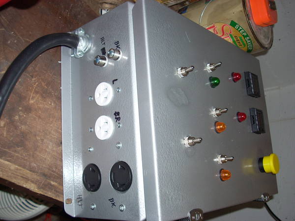
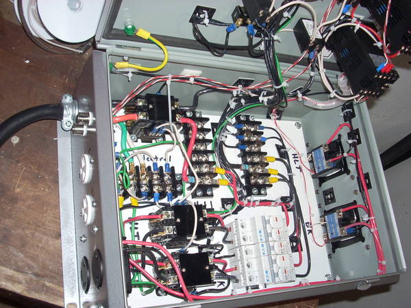
My power routing is - into the case as 6/3 from the spa panel into the neutral and ground terminal blocks and into the 50 amp contactor for the two hots. From the main contactor into a red and black terminal block. From the terminal blocks, I split out the two hots into (2) 25 amp dual pole DIN mount circuit breakers and (1) 15 amp single pole DIN breaker. The 15 amp fed the 120V bus and the (2) 25 amp CB's fed into their own 40 amp contactor controlled by simple spst toggle switches - I really like being able to positively kill a circuit that is controlled by SSR's. The contactors feed to the outlet with one leg broken (controlled) by the (40 amp external heatsink from Auber) SSR on the way there. I also utilized PJ's estop circuit and it works flawlessly.
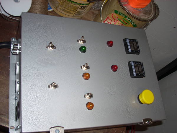
The 3 fuses are the estop circuit, the PID's and the individual circuit contactors and they are all 1 amp fast blow fuses. The PID's are Auber 2352's and I ordered the LED indicator lights from Mcmaster, I went with 120V LED's and they all seem to work fine, even the element firing indicator lights. Yay!
I don't really have a circuit diagram, but it is certainly based on PJ's published stuff here and looking at other builds. I just wired it one sub-circuit at a time and worked my way out by doing the big power stuff first, then the control wiring and outlets and finally hooking up the PID's and temperature sensors last.
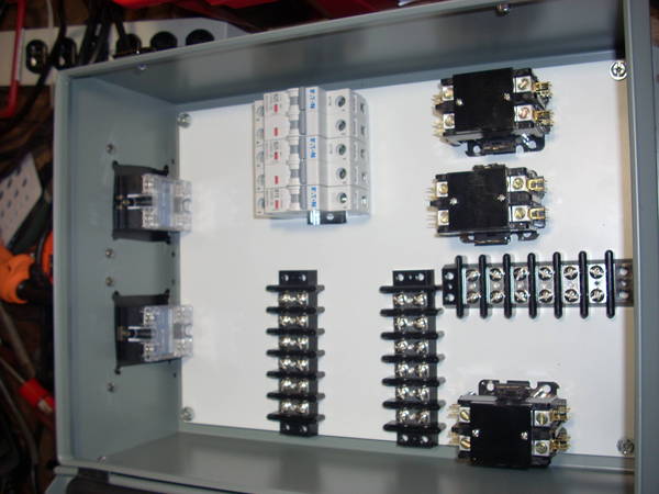
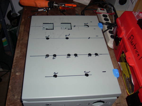
layout of the internal components first
then figure out layout of the door components so there is easy room for everything
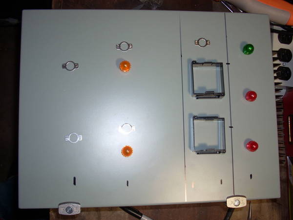
I changed it up a bit before I did the final cutting of the box. I'm pretty happy with the layout. It would have been neat to use DIN terminal blocks as the power distribution busses, but I went with terminal blocks as they are what I knew.
I designed so that I could fire up to two 5500 watt elements at the same time, if I need to. I figured it was just a bit more layout at the beginning to not be mad that I hadn't done it later. I'm going to go with 4500 watt elements, at least initially to give the system more headroom. I can always change the elements later.
It's going to be a 3 tier setup with a 10 gallon e hot liquor tank, a 13 gallon cooler MLT and a 15 gallon keggle. I haver a pump and plate chiller that I'll use to cool the wort and pump it into the fermenters.
My power routing is - into the case as 6/3 from the spa panel into the neutral and ground terminal blocks and into the 50 amp contactor for the two hots. From the main contactor into a red and black terminal block. From the terminal blocks, I split out the two hots into (2) 25 amp dual pole DIN mount circuit breakers and (1) 15 amp single pole DIN breaker. The 15 amp fed the 120V bus and the (2) 25 amp CB's fed into their own 40 amp contactor controlled by simple spst toggle switches - I really like being able to positively kill a circuit that is controlled by SSR's. The contactors feed to the outlet with one leg broken (controlled) by the (40 amp external heatsink from Auber) SSR on the way there. I also utilized PJ's estop circuit and it works flawlessly.
The 3 fuses are the estop circuit, the PID's and the individual circuit contactors and they are all 1 amp fast blow fuses. The PID's are Auber 2352's and I ordered the LED indicator lights from Mcmaster, I went with 120V LED's and they all seem to work fine, even the element firing indicator lights. Yay!
I don't really have a circuit diagram, but it is certainly based on PJ's published stuff here and looking at other builds. I just wired it one sub-circuit at a time and worked my way out by doing the big power stuff first, then the control wiring and outlets and finally hooking up the PID's and temperature sensors last.
layout of the internal components first
then figure out layout of the door components so there is easy room for everything
I changed it up a bit before I did the final cutting of the box. I'm pretty happy with the layout. It would have been neat to use DIN terminal blocks as the power distribution busses, but I went with terminal blocks as they are what I knew.