Step by Step build a 110v portable PID controller

Homebrew Talk - Beer, Wine, Mead, & Cider Brewing Discussion Forum

Help Support Homebrew Talk - Beer, Wine, Mead, & Cider Brewing Discussion Forum:

This site may earn a commission from merchant affiliate links, including eBay, Amazon, and others.
That's 12.5A, that + a pump might be cutting it close for a 15A circuit. I can't find a diagram on that Leviton so I can't be much help in regard to wiring. Once you get it in hand there will be a diagram on the box.

Okay, looks like I will have to get the parts and then touch base. I plan to use the pump linked below though which says on the site it pulls 1.05A so shouldn't I be fine with that and the 1500W element? Thanks again for the help!

http://brausupply.com/products/brew-pump-24v
 
I plan to use the pump linked below though which says on the site it pulls 1.05A so shouldn't I be fine with that and the 1500W element?

You're looking at about 13/15 amps so I suppose you should be fine, so long as we're not talking about more than 3 hours of continuous use. What size is the circuit breaker you are putting this on?
 
You're looking at about 13/15 amps so I suppose you should be fine, so long as we're not talking about more than 3 hours of continuous use. What size is the circuit breaker you are putting this on?

15 amps. I definitely wouldn't get close to more than 3 hours of continuous use.
 
15 amps. I definitely wouldn't get close to more than 3 hours of continuous use.

Finally, is this for a ebiab as in the first post?

I only ask because depending on what you are doing I might wire it so the element can't fire unless the pump is switched on.
 

Nl9mYbO.jpg


For community review

Option #1) Wired as themightyquinn's diagram, element switch enables element and turns on the PID
IWmcab2.png


Option #2) PID is always on, element switch ONLY switches element. This way you can program your PID before the element goes hot. Might should add one more "Light" switch at the input to switch power to the whole box.
pmpwhaT.png
 
Last edited by a moderator:
Thank you! However, I'm not quite sure I understand what you mean in option #2 when you say "element switch ONLY switches element."
 
Thank you! However, I'm not quite sure I understand what you mean in option #2 when you say "element switch ONLY switches element."

In option #1 when you flip the element switch the PID controller is then powered on as well as enabling the heating element to be controlled by the SSR. This is the way it was wired in the first diagram that you asked about.

In option #2 the PID controller is independent of the element switch. The PID will always be on as long as you're plugged into the wall. The element switch is just a manual disconnect for the heating element. This way you can just monitor the temperature or program the PID without the element being able to fire off before you're ready. This is probably the way I'd do it.

Disclaimer: I'm just some guy on the internet. You should get some more experienced opinions first.

I guess I don't see much of a difference since whenever I use the PID I'll be using the element as well. Does anyone have any pros to one way over the other?
 
I guess I don't see much of a difference since whenever I use the PID I'll be using the element as well. Does anyone have any pros to one way over the other?

If your PID can be powered on while your element is powered off, then you will be able to read the temperature. That's how I would go.
 
I guess I don't see much of a difference since whenever I use the PID I'll be using the element as well.

If it were me, I would go with option #2 also.

You say you will be using the PID the same time as the element....... but one day, something will happen. A buddy show up, kids do something stupid, wife interrupts you with... what ever!, but something will happen, and 5 minutes flies by and "poof" your heating elements toast!

I program industrial controls, and I always have to qualify a pump (prove status and flow) before I turn on any equipment, it's just good practice.

:mug:
 
Looks like option #2 is the way to go. I greatly appreciate all the advice.
 
What did you use for your element enclosure to go into the kettle?? Maybe I missed that?
 
Nl9mYbO.jpg


For community review

Option #1) Wired as themightyquinn's diagram, element switch enables element and turns on the PID
IWmcab2.png


Option #2) PID is always on, element switch ONLY switches element. This way you can program your PID before the element goes hot. Might should add one more "Light" switch at the input to switch power to the whole box.
pmpwhaT.png

Hi Guys,

After much time reading through threads similar to this I've decided to build a slightly modified Countertop Brutus 20. I have a two pot system with a 10 GA mash tun with a 10 GA kettle equipped to do 5 GA batches. I'm putting in a 1500W element in the kettle to utilize during a RIMS cycle during the 80% volume mash (followed with the other 20% volume room temperature sparge water).

I'll also use the element to heat the wort in the boil alongside my gas stove. Here's where I need help, I have all the parts to wire up my control panel but I wanted to verify a wiring diagram that works with my setup.

I figured this was the best place to post because this control panel is closest to mine. The above Diagram option #2 (that was first mentioned by themightyquinn and then modified by thekraken) is exactly what I'd like to wire my control panel to.

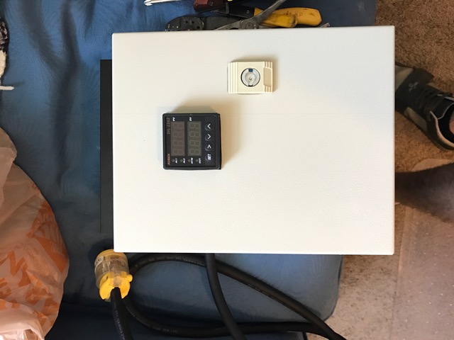
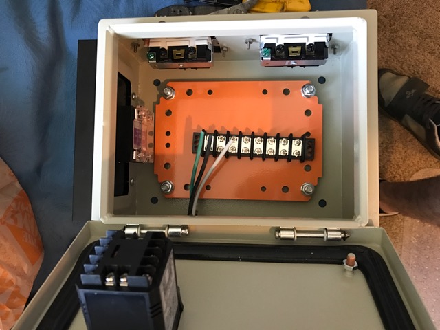
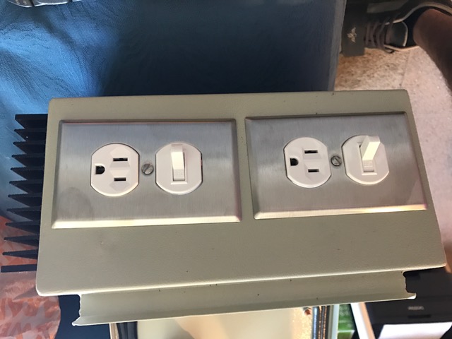
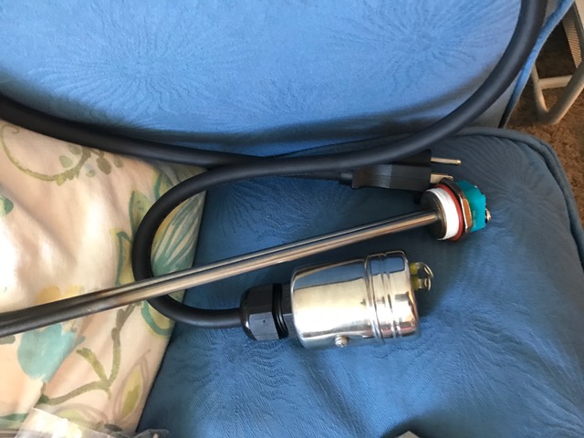
Here's some pictures of what I have so far.

IMG_0815.JPG


IMG_0816.JPG


IMG_0817.JPG


IMG_0818.JPG


IMG_0819.JPG
 
Last edited:
Hi Guys,

After much time reading through threads similar to this I've decided to build a slightly modified Countertop Brutus 20. I have a two pot system with a 10 GA mash tun with a 10 GA kettle equipped to do 5 GA batches. I'm putting in a 1500W element in the kettle to utilize during a RIMS cycle during the 80% volume mash (followed with the other 20% volume room temperature sparge water).

I'll also use the element to heat the wort in the boil alongside my gas stove. Here's where I need help, I have all the parts to wire up my control panel but I wanted to verify a wiring diagram that works with my setup.

I figured this was the best place to post because this control panel is closest to mine. The above Diagram option #2 (that was first mentioned by themightyquinn and then modified by thekraken) is exactly what I'd like to wire my control panel to.

Here's some pictures of what I have so far.

@dropabeet did you wire your controller according to the #2 diagram? If so did it work? I'm looking to do something very similar and would like to know if the diagram is correct (I understand that the ground / neutral may be different according to the switch I purchase).

Thanks in advance
 
I'm too looking for a controller and just did a quick cost tally on the parts based on today's prices and come up with $103 from Amazon and $69 from Auberins...Net $172 round numbers... So let's say $190 to 200 even complete assuming shipping and some odds and ends that one may or may not already have... I'm thinking to go with the basic EZ-Boil Controller instead which only costs a few dollars more...
http://www.auberins.com/index.php?main_page=product_info&cPath=53&products_id=560...

ez boil unit is much better than a pid..I have used and own both...

May I aso suggest you check ebay and sort by price... You will likely find the same seller from amazon selling on ebay for less. I usually do. I would strongly recommend a pt100 temp sensor like this. http://www.ebay.com/itm/RTD-Pt100-T...560657&hash=item1eb2a071b4:g:lL0AAOSwqBJXXWGy

or this one which is better yet..
http://www.ebay.com/itm/RTD-PT100-T...946264?hash=item280fedfa98:g:1SAAAOSw-zxWm6lk

I have both types and preffer the second type since the plugs are easier to use and the cable doesnt kink and is stronger than the stainless braided stuff.

also look at mager brand ssrs, they are the supplier of the ssrs auberins rebrands and sells for double the price plus shipping...

this one is the same ssr as auber sells only with a heat sink for $15 shipped..
http://www.ebay.com/itm/Mager-40A-S...637494&hash=item5b2516545a:g:MWoAAOSwo0JWJzxJ

you can built this exact enclosure for about $100... 120v plugs and outlets are cheap compared to 240v.
 
I realize this is an old thread, but I just found it and I'm converting my pot using Disintegr8or's design. What part was used on the pot to connect the thermocouple?
 
The kraken Did you build your box ?

Sorry I'm responding a year later... better late than never right?

I didn't build this box. I did build a 240v box inspired by this thread. All it is is a 240v "light" switch for on off and a linear potentiometer connected to a $3 arduino for faux pwm to a ssr. Works great for boil controller, and cheap too.
 
Thanks for this post. I just built one and I love it. I got my hands on a turbo 500 boiler brand new for $50 and use this with is like a grainfather setup only I use it to do a precise mash only and run off to my boil kettle.
 
I'm almost done with this build. I wasn't clear about what to use to attach the heat probe, but did plenty of research. It's all good.
 
@dropabeet did you wire your controller according to the #2 diagram? If so did it work? I'm looking to do something very similar and would like to know if the diagram is correct (I understand that the ground / neutral may be different according to the switch I purchase).

Thanks in advance

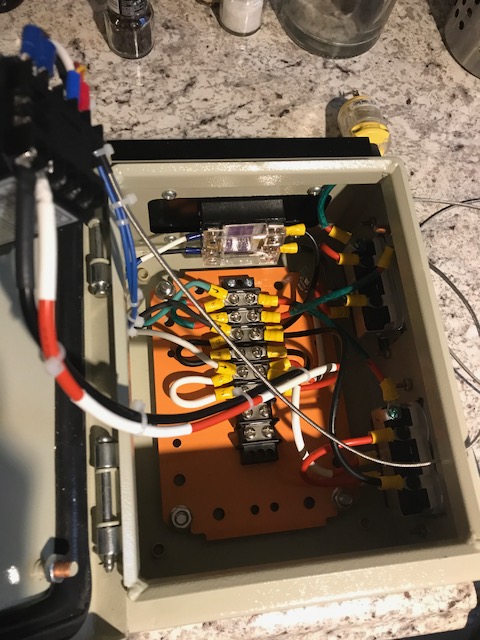
@MusicalBrewer Sorry for the late response. Yes I went with option #2, works just as described - as long as your wire the switches correctly. Here's a picture of the finished interior.

IMG_1720.JPG
 
So to clarify does the original wiring diagram (without intergrated pump) allow for the pid to be powered on while the Element is switched off?
 
Affirmative.

If you want the PID to have power when ever it's plugged into the wall you could modify the original schematic like so:

oAKY8Td.png


now the switch cuts power to the SSR and element only.

Whether or not this is advisable, idk. I personally would like to have a "master" switch to kill power to everything which the original drawing achieves, and a second switch for element on/off. Light switches are cheap.
 
Last edited:
If you have a main AC on/off switch, its easier to just use a small DC switch to turn off the SSR control signal (+) for the element.
 
The problem with that is if he SSR fails on the on state you could have the signal switch turned off but the element circuit would still be hot and not know it.
 
The problem with that is if he SSR fails on the on state you could have the signal switch turned off but the element circuit would still be hot and not know it.

If there wasnt a signal switch, you wouldnt know the SSR was stuck on either......
 
Easy enough when you know there is a problem. The point is that if there is a failure a switch on the 120v line will still behave as expected. For example a failed ssr won't be the cause of a dry fire, where as with the configuration you're suggesting you could plug in the controller and have power going to your elements and not know it, dry firing and ruining an element. A switch on the AC side avoids this particular scenario. A dry fire with a switch on the AC side is purely operator error.
 
Last edited:
Fair enough. I suppose that's a pretty safe way of doing it. I guess i live life on the edge.
 

Attachments

  • 20180406_184514.jpg
    20180406_184514.jpg
    3.1 MB · Views: 118
Back
Top