PuckeredPenguin
Well-Known Member
I have searched multiple times looking for info on my particular situation and either I have over looked the correct answer, haven't found one that addresses my issue, or I just havent connected the right dots:cross: At any rate here is:
Project: Motorize my grain mill.
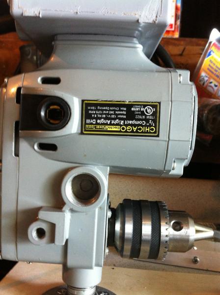
Power source: HF Right Angle 2 speed drill (yes I know cheep, but it will work)
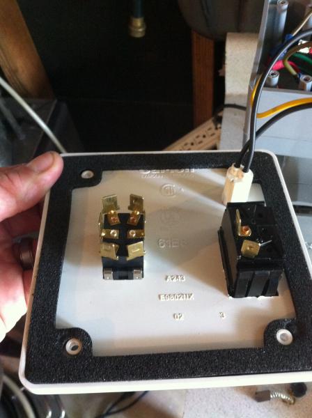
Controls: 4x4 Elect Junction Box w/cover, SPST Master Power Switch, DTDP 20A toggle switch (for directional control) and wires.
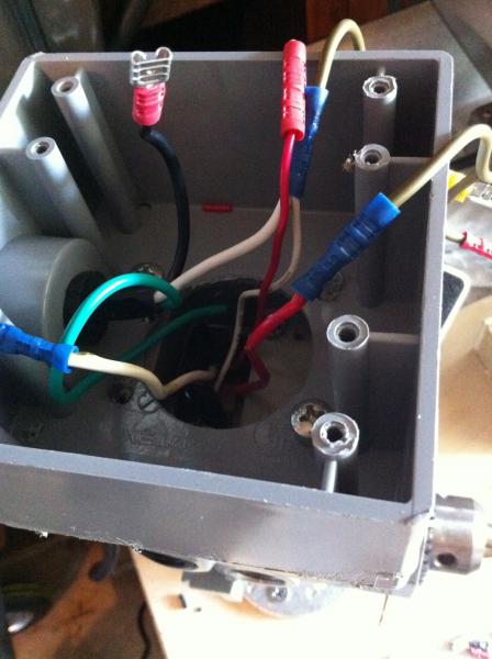
Here is the problem I have run into, the motor has 4 wires going into it 2 red and 2 white: The smaller white and red wires go to the carbon brushes at one end and the larger white and red wires go to the windings.
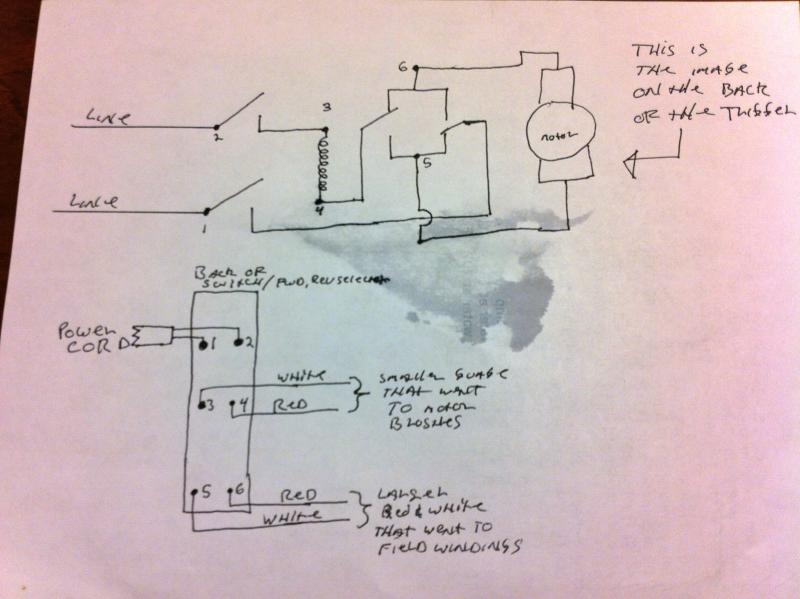
So what I had gathered from other posts on here and from my basic elec knowledge, is that the way the motor was reversed was to switch the direction of current flow through the wires going to the windings by wiring the DPDT switch: See picture.
My plan was to just marry up the whites and reds, connect them to one side of the DPDT switch, have Power in connected to the middle terminals, and crossed jumpers ( connected to the first terminals) to the other switch terminals. But before I tried this something just didn't seem right, so here I am looking for some scolding, possibly a little help and advice.
Thanks in advance
Nick
So I get it if I only had two wires coming out of the motor but I have 4 So any of you EE's out there or fellow DIY-ER'S who have a solution or could at east point me in the right direction I would greatly appreciate it. I have also included some pics of the motor in it's current state. Once I get it all dialed in I will post some completed shots


Project: Motorize my grain mill.
Power source: HF Right Angle 2 speed drill (yes I know cheep, but it will work)
Controls: 4x4 Elect Junction Box w/cover, SPST Master Power Switch, DTDP 20A toggle switch (for directional control) and wires.
Here is the problem I have run into, the motor has 4 wires going into it 2 red and 2 white: The smaller white and red wires go to the carbon brushes at one end and the larger white and red wires go to the windings.
So what I had gathered from other posts on here and from my basic elec knowledge, is that the way the motor was reversed was to switch the direction of current flow through the wires going to the windings by wiring the DPDT switch: See picture.
My plan was to just marry up the whites and reds, connect them to one side of the DPDT switch, have Power in connected to the middle terminals, and crossed jumpers ( connected to the first terminals) to the other switch terminals. But before I tried this something just didn't seem right, so here I am looking for some scolding, possibly a little help
Thanks in advance
Nick

So I get it if I only had two wires coming out of the motor but I have 4


