PWM..Show us How

Homebrew Talk - Beer, Wine, Mead, & Cider Brewing Discussion Forum

Help Support Homebrew Talk - Beer, Wine, Mead, & Cider Brewing Discussion Forum:

This site may earn a commission from merchant affiliate links, including eBay, Amazon, and others.
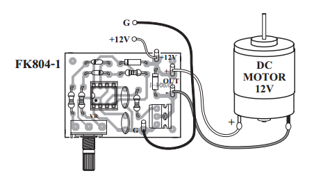
While powered and intended to pulse, check voltage between G and the other side of the closest resistor, R4.
(this is pin three, but you are less likely to short against pin 2 or 4 accidentally.

I - If this voltage pulses, then the board is good except for the power transistor... remove it and the resistor, solder a wire into the hole of the resistor nearest the G terminal and run to your SSR...

II -if this voltage does not pulse, check voltage between pin 1 and pin 4 directly on the 555
a - if no voltage, find break or short
b - if voltage, check voltage between pin 2 and pin 4 with the POT turned in a few different positions
1 - if voltage is variable, replace 555 and/or cap
2 - if voltage does not vary, check for open/break near POT and R2,R3
a - remove pot and test/replace
b - if still not fixed, buy a new kit and have a high school electronics kid assemble for you...
 
Well, it was the Pot. I ordered a few online after testing the one I had (Which worked fine at one time!) and noticed it was going full on at Zero and was not stopping at 500K at the high end. Very messy swipe in the middle too.

Anyway, I just soldered it at work and can test it next brewday. Time to start mounting it in a box.
 
Have any of you actually put the PWM between the PID and the SSR and did it work?

In this case, are you using the PID for mash control, then switching the PID to 100% output and controlling with PWM?

I suspect that would work fine, but I haven't designed a circuit like that. I have two separate kettles for HLT and BK, so I have two output circuits.

If you were using a single vessel, I can see how that might be nice, but you could also wire a selector switch in and bypass the PID altogether.
 
Yes, I do BIAB so the HLT, mash tun, and boil kettle are one and the same.
I had a PID with the manual feature, but that went bad so I'm using one I got of eBay which doesn't have the manual feature. I like the idea of a knob instead of buttons to control the rate of boil anyway.
 
I want to try hooking them up in series so as to have one less hole in my control box. If it doesn't work, then I will use a switch.
 
I realize this is an old thread, but I'm trying to wire the PWM using the bakatronics circuit and can't figure out the wiring because most of the links provided here are dead. Where does the 240V get wired to on the board?

bakatronics.png
 
I have one of these on an electric brewing panel that I recently bought with a rex 100 pid. The guy I bought it from left town before he could show me how to use it and while trying to figurre it out I fried the ssr. How(manual or auto) to set the PID and at what temp for boil and what level to set POT? IT also doesn't have a GFCI but I had an electrician friend add a spa panel GFCI but it would not stay on so it was removed. Any help would be great.
 
Plusultra - PID is not for the boil, you do not temperature control a boil kettle, you power control it with PWM...

The PID is likely for a HLT or RIMS that needs temperature control, but theoretically, they could be using it for something else and we should not go down that road unless needed

This thread is for the PWM, so if you have questions about your PID or your specific panel, I would highly suggest that you start a new thread, and include detailed part number information of the PID and work up a drawing that identifies all terminals correctly.

If you have a bakatronics PWM board and have questions about it, detail where each connection on the board goes, and relate to us how it may be different from that diagram above your post..
 
Thank you for the reply. I'm obviously not up on this system and until your reply had not traced out all of the wires. I figured the 2nd PID would control the BK and didn't understand why or how the POT would also control it. I guess you just do a visual and then alter the boil by using the POT. My second PID is for the Mash. OOPS! Through all of my reading and your response I get it. Sorry if I messed up this thread but I really appreciate your help.
 
Buy this: PWM DC Motor Speed Controller, 1.5 Amps
Replace C1 with a 2.2uF capacitor to lower the frequency.
Use a 12V wall wart as a power supply to the PWM board.
Connect the output of the PWM board to a SSR to control your boil.

This is how I did it and I'm very happy. Cheap, easy, responsive control.
Hey, I've recently come to the conclusion that the power controllers I've been using like the above are no good (and scarily dangerous), and I'd like to do something like you suggested although not being in the us (UK) I'm not totally sure what I want in terms of controller and relay. I gather I'm after a zero crossing relay and a NO type? The power I'm controlling is 7k so I suppose I'm wanting 32A or will 25 suffice?

The main thing is identifying what pwm controller will get me to a reasonable frequency, frankly all of this was completely foreign to me until I read your post.
 

Latest posts

Back
Top