
JVD_X
Well-Known Member
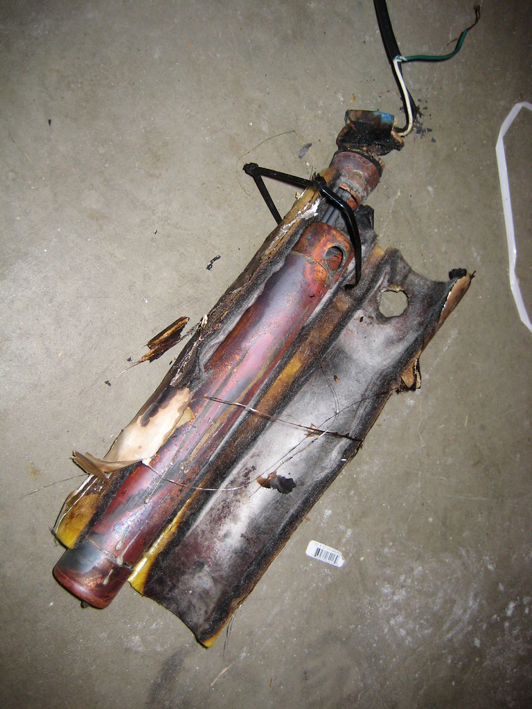
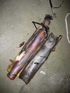
Well, I burned out my heating element. I didn't realize I had a very very slow running mash... welp. During the meltdown, the plastic around the element base melted away and POP went the GFCI.
Plastic everywhere.
I ended up having to do a decoction to get the mash up to temp. That was a pain because I wasn't ready for it and I had never done one before.
With that said... I think I like decoction mashing and plan on trying more in the future!
Plastic everywhere.
I ended up having to do a decoction to get the mash up to temp. That was a pain because I wasn't ready for it and I had never done one before.
With that said... I think I like decoction mashing and plan on trying more in the future!


 )
)