Mash Tun Manifold overengineered?

Homebrew Talk - Beer, Wine, Mead, & Cider Brewing Discussion Forum

Help Support Homebrew Talk - Beer, Wine, Mead, & Cider Brewing Discussion Forum:

This site may earn a commission from merchant affiliate links, including eBay, Amazon, and others.

ernestmyname

Well-Known Member
Joined
Mar 31, 2009
Messages
53
Reaction score
0
Location
Clemson, SC
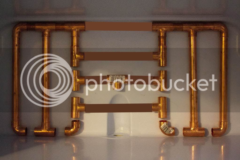
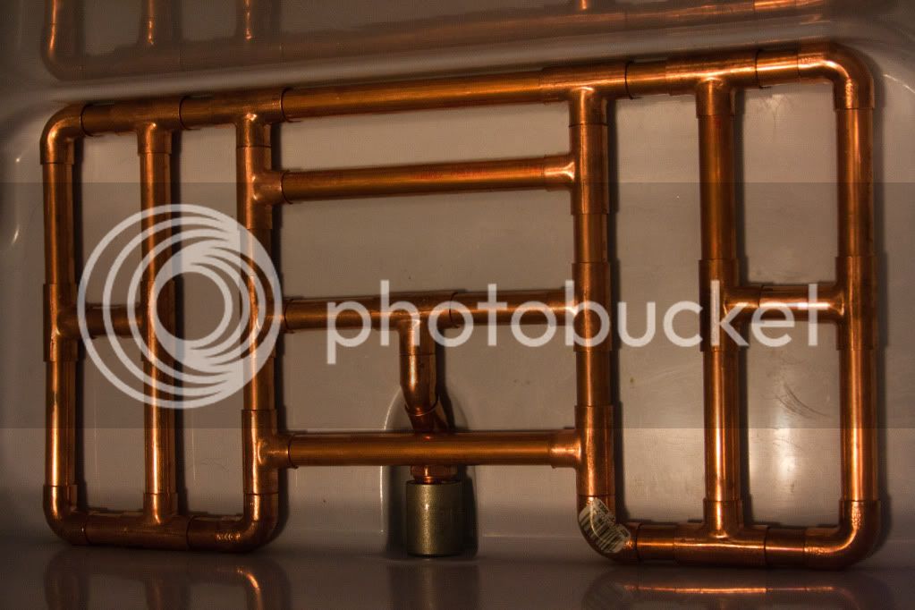
I was given this rectangular cooler and am considering using this setup for my mash tun manifold. It isn't official but I was wondering what you guys think. Cost really isn't an issue since I got to return my 10 gallon igloo cooler! :ban: I really wanted to incorporate two different drain locations, thinking that it would make the draining a little more uniform. The only downside to this setup I can see is I will have to solder the joints to ensure a good siphon. Otherwise, I will lose a lot of wort at the end of the drain. It will also be more difficult to get that last little bit of wort out the grain. Thoughts?

IMG_8829.jpg


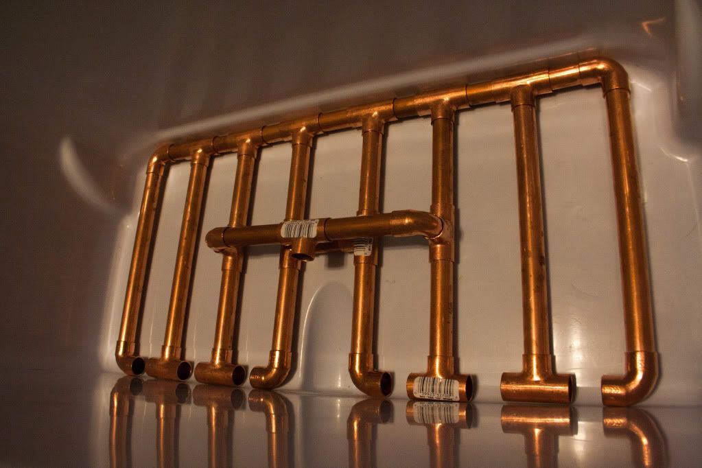
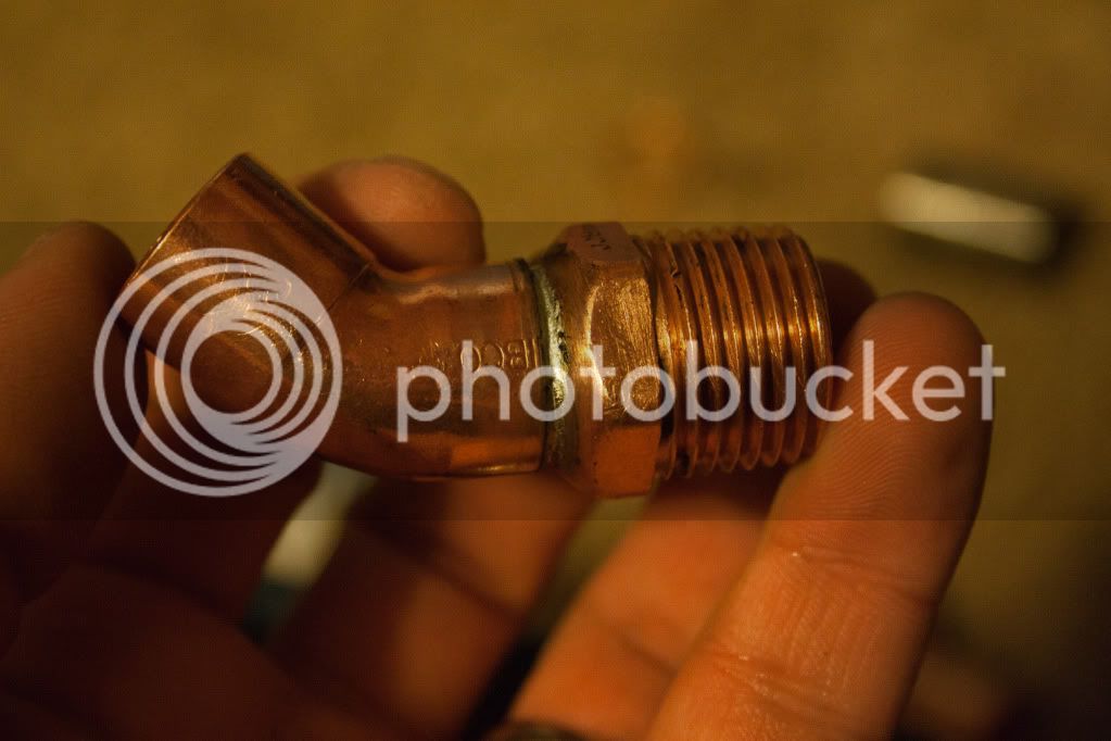
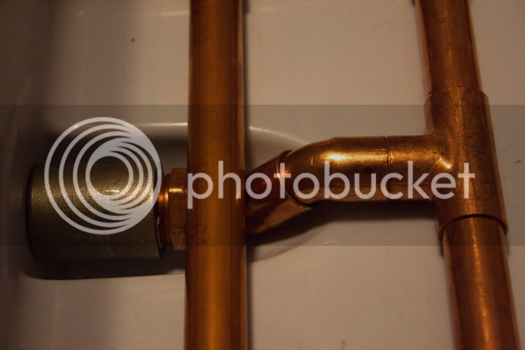
BTW, to clarify, I planned to connect the drain tube to the exposed T fitting pictured. Possibly with high temp tubing to allow it to be connected and disconnected easily.

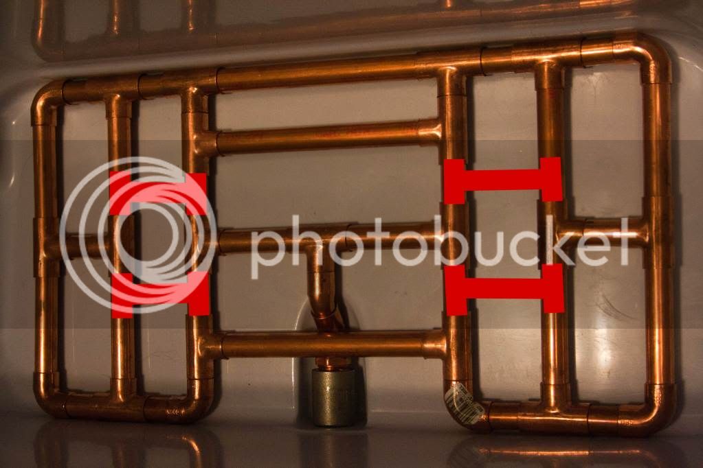
To clarify further, the fittings on the closest side have not been populated with the connecting pipes. :D
 
I can't imagine loosing syphon - even if you dont solder any of it. The runners are drilled all over the place, which is the path of least resistance. I would leave it just finger fit tight and see how it does. You may want keep it at least in sections if you ever have to give it a total clearing out down the road.

and it looks like you can go flexible righ into that center spanner, and delete the raised t-bar. With the drain tube above the entire manifold, that might be your set fluid level when draining. If that made sense. the manifold body looks like it could retain 12-16 ozs!
 
My understanding is if the water level went below the raised portion and air was able to get by the fittings, it would lose siphon and would only drain to basically the bottom of the raised portion. Those parts, at least, would need to be soldered.. Originally, I was going to have three drain locations and use tubing for all of them. but, the center was too narrow for a T. I could for sure use tubing and cut down on the total height significantly.
 
If you have the holes facing the bottom of your tun you should leave very little liquid in you system and that little bit is not a concern anyway.

However if you must, fill up the tubing when assembled but not drilled and empty in a measured container, add this extra to your sparge and voila!

I agree with steakandale about solderning some but not all of this for cleaning!

Looks good to me, good luck!
 
So the question of whether or not this thing was over-thought is pretty self-explanatory.. :eek:

If you thought it was ridiculous now, just wait. I will hopefully post pics of the new, final, design tonight. many changes were made but for the good. :rockin:
 
It will certianly work as is. But I thought I'd suggest changing the orientation by 90 degrees. The Tees in the picture are on the long length of the cooler. I would put the Tees along the short length of the cooler, only to simplify construction and cleaning.

Just a thought. Have fun.
 
WOW! Thats around 50 pieces of copper! I would guess that you will lose a siphon at the highest point of an unsoldered joint? The goal here is to fly sparge?

It is beautiful, I'll give ya that!
 
But I thought I'd suggest changing the orientation by 90 degrees..

I used the orientation it is in at the moment based on Palmer's "how to brew". With the T's along the long side of the cooler, it ensures I don't drain near the wall... I am wondering if my new idea is even worth the change. It would basically make the draining slightly less uniform but would allow the highest point to be as low as the other copper members.
 
So this is an alternate design.. If I went this way, I would solder all T's that are in the center of the cooler and put slots in them as well as the pipes. Do you guys like option A or option B? I have already mocked up the lowest member in the picture and it will actually go just behind the street 45 that will go from the bulkhead to the T connector.

IMG_8832edited.jpg
 
I think you have the same area of coverage either way, so whichever works easiest for you. The only change I would suggest is putting the T for your drain on the piece closest to the drain, that way it can also angle down and get more wort out of the tun.
 
I think you have the same area of coverage either way, so whichever works easiest for you. The only change I would suggest is putting the T for your drain on the piece closest to the drain, that way it can also angle down and get more wort out of the tun.

It would actually be more difficult that way.. A street 90 up from the bulkhead and a T is actually taller than I can achieve with two street 45's out of the bulkhead and over to that center drain.
 
It would actually be more difficult that way.. A street 90 up from the bulkhead and a T is actually taller than I can achieve with two street 45's out of the bulkhead and over to that center drain.

Whatever works the best is what I'd go for. Actually, if you take the T that you have on the mock up and move it closer to your bulkhead, you might not need any 45s or 90s to get the job done (this is what I was aiming for earlier). If you use high temp hose to the T and a couple of stainless steel hose clamps it should work out well. Something like this (but not quite the same design):
Basically, as long as you aren't getting stuck sparges be happy and use whatever works for you.

Picture014.jpg


Picture017.jpg
 
So I finally got some time to mess around with the manifold.. I am going to try one more thing that I think will help uniformity before I call it complete. Then it will be time to cut the slots. But this is what I have now...

The drain hole in the cooler was too small for my bulkhead, 1/2" copper fitting, and 45 elbow. I had to make the fittings a little smaller/shorter. Since there was significantly less contact area, I went ahead and soldered this piece..

IMG_8846.jpg


I really like the way it turned out..

IMG_8851.jpg


The highest part of the manifold is literally resting on the bottom of the cooler. And the drain is below that. :rockin: Considering how much volume the bulkhead takes up I am guessing I should be able to drain all but a couple ounces of wort.

IMG_8854.jpg


BTW, this will require a lot more effort but this is what I want it to look like before I call it quits. It isn't nearly ridiculous enough as is. And the only prescription is more fittings!. :D I should add that if I hadn't been able to return my beverage cooler I would have never spent this much on my manifold.. When I finish it I will post up a price list. I could have probably bought something pre-made that would have had better efficiency but it wouldn't have been nearly as fun...

IMG_8851edit.jpg
 
looks really clean..

Yeah, other than the animal hairs that are stuck to some of the T's.. :D I definitely need to get some alcohol to those things to get the glue off that held the bar codes on.. I soaked all my fittings in PBW but it didn't dissolve that type of glue...
 
haha, I have a great pyrenees and 2 cats (I have a lab/pit mix also, but he's got short fur) at home - I've got fur all over everything. It'll settle out into the trub :)
 
Once I get a hold of a cut-off saw things will start looking a lot more interesting. The T's I have hilighted in red will need around an 1/8 of an inch taken off in order to cram them all in there. Then they will be soldered and notches cut into the T's as well as the regular pipe. I haven't completely figured it out yet but I am going to solder only the T's that need notches in them.. Yet I still want to be able to get it apart enough to clean it easily.. Updates in the near future! I can't wait to do my first all-grain batch!
 
I like and dont think it is over kill. It's BA!

This was mine for a 5 gal MLT. All dry fitted and I get every last drop out.

SANY0421.jpg
 
So I finally got some time to mess around with the manifold.. I am going to try one more thing that I think will help uniformity before I call it complete. Then it will be time to cut the slots. But this is what I have now...

The drain hole in the cooler was too small for my bulkhead, 1/2" copper fitting, and 45 elbow. I had to make the fittings a little smaller/shorter. Since there was significantly less contact area, I went ahead and soldered this piece..

IMG_8846.jpg


I really like the way it turned out..

IMG_8851.jpg


The highest part of the manifold is literally resting on the bottom of the cooler. And the drain is below that. :rockin: Considering how much volume the bulkhead takes up I am guessing I should be able to drain all but a couple ounces of wort.

IMG_8854.jpg


BTW, this will require a lot more effort but this is what I want it to look like before I call it quits. It isn't nearly ridiculous enough as is. And the only prescription is more fittings!. :D I should add that if I hadn't been able to return my beverage cooler I would have never spent this much on my manifold.. When I finish it I will post up a price list. I could have probably bought something pre-made that would have had better efficiency but it wouldn't have been nearly as fun...

IMG_8851edit.jpg

so where's the pricelist? don't forget to factor in the increase cost of materials :D
 
I think most things in brewing are over engineered, it looks great. I had something similar setup when I was running a cooler. Let us know how it works.
 
Back
Top