Trouble with Control Panel...Please Help

Homebrew Talk - Beer, Wine, Mead, & Cider Brewing Discussion Forum

Help Support Homebrew Talk - Beer, Wine, Mead, & Cider Brewing Discussion Forum:

This site may earn a commission from merchant affiliate links, including eBay, Amazon, and others.

Tfire136

Active Member
Joined
Nov 25, 2010
Messages
42
Reaction score
1
Location
Dighton
Whats up everyone,

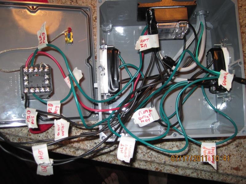
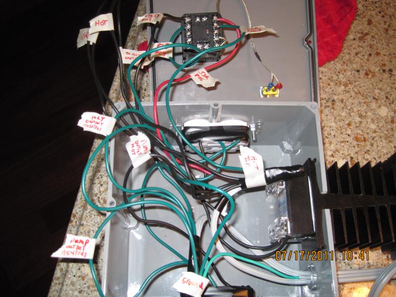
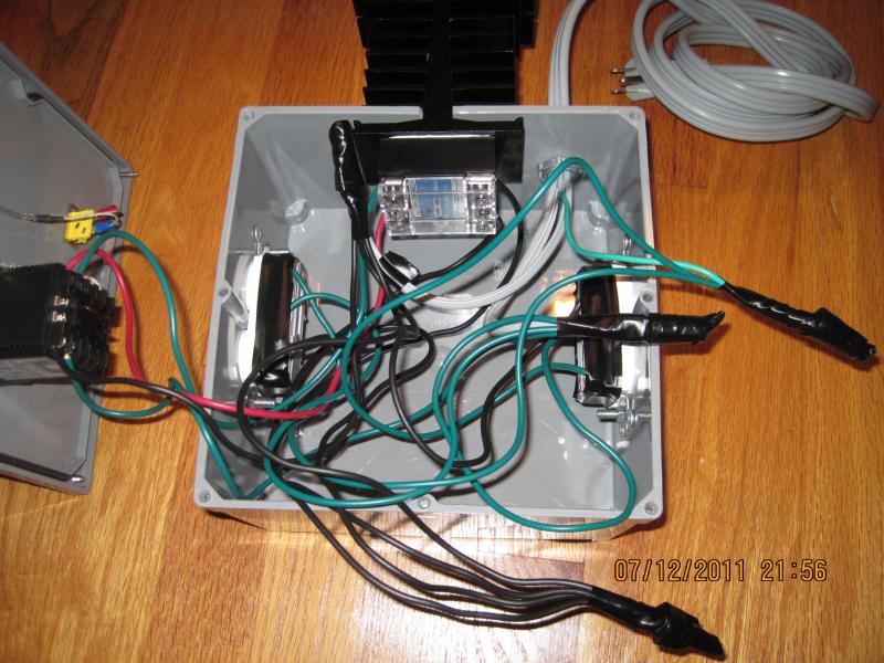
I am in the middle of my Countertop Brutus build and tested out the HLT hooked up to the control panel for the first time. I have run into a couple bumps that I am hoping to get help with. My dad and I wired up the control box with the PID, SSR and 2 outlets for the pump and the HLT. We ran the hot into the box and jumped to everything that needed power with the use of wire nuts. we also used another jumper that had the 2 SSR wires and a hot wire, then hooked it to the HLT outlet. Everything is grounded no problem and the neutral wires seem to be in the right place. When I did my test run, the PID turned on and the probe was holding the proper temp within 2 degrees (I verified with a thermometer). My issue is that the SSR never seemed to open and close. The OUT light on the PID did not light up. When I ran the autotune, the element seemed to heat up as if I plugged it directly into an outlet. I set the autotune for 150 degrees, and when it hit 198 degrees I shut it off figuring that something was wrong. Everything seems to be working great except for the heat to the element not being controlled. I plugged a light into the kettle outlet and it never turned on and off.....just stayed constant which tells me that the SSR may not be working properly. I know if anyone can help me get this thing up and running (safely) it will be you guys. Thanks!

P.S I tried to attach a couple of pictures (hopefully it works lol). The black wires are hot and the SSR wires, and the green wires are neutral and ground.
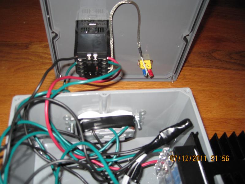
IMG_2062.jpg


IMG_2063.jpg


IMG_2061.jpg
 
I also just double checked to polarity between the PID and the SSR and everything looks good. If anyone needs more picture just let me know and I will post more. Thanks.
 
Were they new SSRs? If they are used, they can, and often do, fail in the on position (always hot). Your light bulb test indicates that might be the case. Also, check the voltage from your PID low-voltage leads to the SSR. If the SSR doesn't receive a signal, it won't activate.

It's real hard to trace your wiring due to just two colors. So I can't comment there.
 
Just a couple more pictures I took with everything labeled....I figured it may help follow everything.

IMG_2064.jpg


IMG_2065.jpg


IMG_2066.jpg
 
Were they new SSRs? If they are used, they can, and often do, fail in the on position (always hot). Your light bulb test indicates that might be the case. Also, check the voltage from your PID low-voltage leads to the SSR. If the SSR doesn't receive a signal, it won't activate.

It's real hard to trace your wiring due to just two colors. So I can't comment there.


Its a brand new 40A SSR from Auber. I will check the voltage.
 
I went back and check out the PID contol settings. I found that the "OUTY" setting was set to 1 which disabled the SSR output. I changed it to 2 which is "SSR PID control Output". The "OUT" light and the light on the SSR is now blinking in sync. I plugged a lamp in and it still does not flash at all. I guess I can try filling the pot with some water and running autotune again....any other thoughts or settings I should change. I changed the HY band from 3 to 0 and made sure that the K type probe setting is selected. Maybe this thing is wired right and it is a program problem with the PID??
 
Only other thing that comes to mind is to try a light bulb test with the output from the SSR directly. Bypass the outlet altogether. It's still really hard to trace your wiring from the pictures. But if you take the outlet out of the path, that will at least help you isolate the offending circuit. I'm assuming your pump is manual? And that the pump outlet is always hot? Is there a possibility that you've are testing with the wrong outlet? Just throwing out ideas...
 
Only other thing that comes to mind is to try a light bulb test with the output from the SSR directly. Bypass the outlet altogether. It's still really hard to trace your wiring from the pictures. But if you take the outlet out of the path, that will at least help you isolate the offending circuit. I'm assuming your pump is manual? And that the pump outlet is always hot? Is there a possibility that you've are testing with the wrong outlet? Just throwing out ideas...

Thanks for the ideas....I am running autotune right now and will see what I come up with. The pump outlet is manual, and is switch activated. How would I conduct a light bulb test with just the SSR??? I just want to do it safely. Would having the 2 SSR output wires connected to a hot wire have anything to do with it ie: should I maybe try just connecting the 2 SSR output wires to the hot on the outlet and leave the hot wire out of the picture?? I will try and take a couple more pictures. I am also just throwing out ideas at this point.....its getting frustrating to say the least. Thanks again.
 
Thanks for the ideas....I am running autotune right now and will see what I come up with. The pump outlet is manual, and is switch activated. How would I conduct a light bulb test with just the SSR??? I just want to do it safely. Would having the 2 SSR output wires connected to a hot wire have anything to do with it ie: should I maybe try just connecting the 2 SSR output wires to the hot on the outlet and leave the hot wire out of the picture?? I will try and take a couple more pictures.

You could just take the two ssr outputs and wire those directly to the light bulb. Your idea of just having the ssr ouputs feed one outlet (without the additional hot leg) alone is probably a good idea. Either way, you should isolate the PID/SSR combo to make sure they are working correctly. I think it's in your wiring.
 
Reelale....thanks for the input. Tried the light bulb thing, and it did not work. This thing has been driving me nuts and more importantly has cut into my brew time. I am going to post a thread and see if there is a member who is experienced with this stuff who I can send it to (and compensate) for getting this thing up and running. Its all put together and would take someone who knows what they are doing 30 seconds to figure it out.
 
Reelale....thanks for the input. Tried the light bulb thing, and it did not work. This thing has been driving me nuts and more importantly has cut into my brew time. I am going to post a thread and see if there is a member who is experienced with this stuff who I can send it to (and compensate) for getting this thing up and running. Its all put together and would take someone who knows what they are doing 30 seconds to figure it out.

A clear wiring diagram would help a lot. It is almost impossible to cypher the wiring as you have it. One thing that doesn't help is that you are using green wire for both your ground circuits and your neutral circuits. I tried my best to follow your connections to and from the SSR. No dice. That is the critical issue at this point and I cannot see it at all.

Sorry.
 
Reelale....thanks for the input. Tried the light bulb thing, and it did not work. This thing has been driving me nuts and more importantly has cut into my brew time. I am going to post a thread and see if there is a member who is experienced with this stuff who I can send it to (and compensate) for getting this thing up and running. Its all put together and would take someone who knows what they are doing 30 seconds to figure it out.

No problem. Hope you get it working. A clear diagram of your wiring will allow someone here to troubleshoot it on-line. I have the Auber 2352, but it sounds like your PID is a different model if you can switch between SSR and relay output. I can send the PID parameters if you think that would help. Also, just remembered, when you test, you need to set the PV value close to the SV value (temperatures close together). And keep your temperature sensor close to the light bulb so it reads the temp change. If there is a large gradient, the PID will send signal for full power. And since that temperature doesn't change unless your temperature sensor picks it up, it will always stay on. That's how I tested mine anyway.
 
A clear wiring diagram would help a lot. It is almost impossible to cypher the wiring as you have it. One thing that doesn't help is that you are using green wire for both your ground circuits and your neutral circuits. I tried my best to follow your connections to and from the SSR. No dice. That is the critical issue at this point and I cannot see it at all.

Sorry.

Thanks P-J...... as soon as I get home from work tonight I will put that together and post it. I am going to sketch it out.....that may be the best way to go.
 
Would having the 2 SSR output wires connected to a hot wire have anything to do with it ie: should I maybe try just connecting the 2 SSR output wires to the hot on the outlet and leave the hot wire out of the picture??
Ok... this is the comment that set of an alarm for me.

The SSR does not have 2 "output" wires.

Two of the terminals are labeled "+" and "-", and those are for the DC control signal from your PID.

The other two terminals are labeled "1" and "2". One of those should be connected to the source of power in yor panel and the other should be connected to your heater element's receptacle. (It doesn't matter which one you connect to the receptacle, it just matters that one goes to the receptacle and the other goes to your hot line).

When the SSR control is active, terminals 1 and 2 of the SSR are bridged together allowing current to flow through the SSR and to the receptacle.

YES!! That was it. Walker, I read your post and a light bulb went off lol. How can a relay control power output if it has no electricity??....it can't lol. I now see exactly how the PID / SSR works. I added a hot wire to the SSR and another line from the SSR to the outlet......works great! I ran the autotune mode and am in the process of testing manual mode to boil. I noticed that the PID was reading about 3 degrees low of what the actual temp is, but I read that it can be adjusted in the settings menu. Thanks everyone for helping me get this up and running.


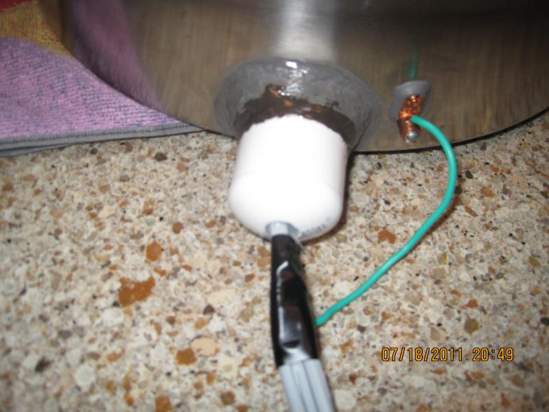
On a side note, I used a ton of JB to seal the element to the pot. everything is water tight and looks good. I added a PVC cap to cover the element and instead of filling the cap with JB, I filled it with aquarium grade silicon which apparently is only rated up to 140 degrees (didn't realize it at the time). The silicon seems like it may be getting soft by what I can see at the end of cap where the plug is sticking out. Would adding a little JB to the end of the cap keep everything sealed up just in case the silicon got to soft??

Thanks again!!

IMG_2071.jpg
 
woah.... you actually sealed the element directly to the pot with JB Weld?

What will you do if you ever have to replace the element?!
 
woah.... you actually sealed the element directly to the pot with JB Weld?

What will you do if you ever have to replace the element?!

Start drilling the other pot I have lol.....I actually drilled the hole for the element to low on the pot. I was unable to get the element nut on the inside of the pot. At least I don't have to worry about it being water tight. This was my first project where I actually used some of these tools I have laying around the house.....its been a learning experience lol.
 
I actually drilled the hole for the element to low on the pot. I was unable to get the element nut on the inside of the pot.

You could have JB Welded just the nut, and on the outside of the pot. Then you would have a place to just screw the element into the pot and you could remove it whenever you wanted. :D
 
More importantly what will he do when the JB Weld fails and hot liquid starts pouring out?

I'd get out a chisel, remove the JB Weld and have a proper nut welded on if you can't do it yourself.
 
yeah, I was wondering about the JB Weld failing. I've never used it to seal up something like a kettle, but I'd be a little worried about it failing.

You've got ground fault protection, right TFire?
 
yeah, I was wondering about the JB Weld failing. I've never used it to seal up something like a kettle, but I'd be a little worried about it failing.

You've got ground fault protection, right TFire?

I do....not a bad idea about having the nut welded. I will have to look into that. I have done 3 tests so far which have all looked good, but that certainly does not mean the JB couldn't fail in the future. Now that I have put all this stuff together I have picked up some great tips, and future builds should go smooth. This Countertop Brutus is absolutely perfect for my purposes. The only thing left to do is build the CFC and hook everything to the pump. I do think the pot I used is too big (a 9g Bayou Classic). I still have to add the insulation and hope it can hold a good boil. Thanks again for everyone's input.
 
Back
Top