Stir plate not changing speeds

Homebrew Talk - Beer, Wine, Mead, & Cider Brewing Discussion Forum

Help Support Homebrew Talk - Beer, Wine, Mead, & Cider Brewing Discussion Forum:

This site may earn a commission from merchant affiliate links, including eBay, Amazon, and others.

carkom

Active Member
Joined
Dec 9, 2010
Messages
32
Reaction score
6
Location
Bend
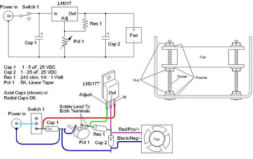
So I've been reading for like 2 hours now and I can't find a solution to my problem. I used the schematic below.

Voltage regulator - LM317T
Resistor - 330 ohm
Pot - 5K-Ohm 0.5W linear-Taper from Radio Shack
Capacitor's - 0.1uF 50WVDC Ceramic Disk (both)
Fan rating - 12V 200mA
Power supply output - 12.5V 0.64A

When I plug the fan in it starts up and my pot doesn't change the speed in the least bit. What am I missing?

2746854079_cc609a0d77.jpg
 
FWIW, if the pot has three legs, there will be a fixed resistance between two of them equal to the pot's value. The third leg is attached to the wiper and provides the variable resistance relative to either of the other two. The wiper is usually the center leg.

That is why the circuit layout indicates that two of the legs are shorted together. Make sure you have shorted the wiper leg to only one of the other legs. And not the two fixed legs together as this will simply short across the entire pot and result in no variable resistance.

In addition, make sure that the legs of the LM317 are correctly connected and isolated.
 
The Pot is good (tested with a multimeter, goes from no resistance to around 5000). I checked, and the middle leg is the wiper which is what's jumped. The LM317T is connected right.
 
You dont want to short the center leg to one of the other legs like you have it. you want to use the center leg and 1 of the 2 side legs. Try just removing the resistor you have across both legs and just attach it to the center leg. I bet that will fix the issue.

EDIT: Also wanted to add if after you do that the knob works 'backwards' you can switch the wire you have on the side leg to the other side to have it go the other way.
 
Connecting the wiper to one of the fixed contacts has nothing to do with why the OP's implementation isn't working. Indeed, that is a recommended way to connect a potentiometer, as the resistance across the pot will never go infinite as can happen when a wiper doesn't make good contact with the resistance surface.

The pot wiring is fine. Something else is wrong...

Cheers!
 
Is the DC voltage measured across Cap2 changing with Pot1 adjustment? If so, what is the range?

The circuit is predicted to produce about 12 volts when Pot1 is adjusted for 2000ohms, which is less then half of the available adjustment It will not rise above that, given your input voltage. In addition, it will take about 6 to 8 volts to get the fan spinning, which is at about 900 to 1300 ohms. Therefore, most of your speed(voltage) adjustment is during a fairly limited area of Pot1 adjustment.

FWIW, I fine tuned my LM317 circuit by making changes to Res1 and Pot1 plus an additional fixed resister in series with Pot1. I determined what minimum and maximum voltages were necessary and adjusted the circuit to approximate them at the full range of Pot1.
 
It turned out to be a defective regulator. I replaced it and it's working now. As you said raouliii it's very sensitive to changes in the pot and maxes out after about a quarter turn. What resistor are you using, my calculations tell me that a 550 ohm resistor would give me a more desirable range. Thoughts?
 
There are LM317 calculators online which use a 1.25(1+Pot1/R1) approximation such as this one.

A few considerations to maximize adjustability: You really don't need any outputs below maybe 5v and you can't obtain outputs over 12v. A fixed resistor in series with Pot1 will raise the minimum.

Something like R1=1K, Pot1=5K and Rfixed=3.5K results in a theoretical output range of 5.6v (Pot1=0) to 11.9v (Pot1=5k). Adjustments can be made depending on available values and actual results.
 
This is a great idea. Do you have a diagram of where the "in series" resistor should go? Thanks!
 
This is a great idea. Do you have a diagram of where the "in series" resistor should go? Thanks!
Relative to the schematic it can be placed in between Pot1 and the - buss along the bottom. Relative to the diagram, place it between the left leg of Pot1 and the - terminal of Cap1. You are basically replacing Pot1 in the original with the series resistance of Pot1+Rfixed.

A series connection of resistors looks like this: ---{Pot1}---{Rfixed}--- and their values simply sum together.

Keep in mind that the calculations are somewhat theoretical in that there are tolerances associated with resistors but those values should get you close. There is quite a bit of flexibility. If you can't find 3.5k then a series connection of 2.8k and 700 would work or even a 3.4k or 3.6k total.
 
just curious, why the over complication with the stir plate? Here's a picture of mine - simple and works great.

under.jpg


It's just a 25ohm pot, pc fan, a rocker switch, and a 12v power supply (washer and hd magnet sit on top of the fan).
 
just curious, why the over complication with the stir plate? Here's a picture of mine - simple and works great.
.......

It's just a 25ohm pot, pc fan, a rocker switch, and a 12v power supply (washer and hd magnet sit on top of the fan).
A simple rheostat / voltage divider circuit doesn't have the fine control that a voltage regulator circuit provides. In addition, the potentiometer must be rated such that it can dissipate the heat generated internally at low fan speeds. 12v across 25ohms requires over 5 watts of heat dissipation capacity.

A voltage regulator circuit is simply a more elegant solution to fan speed control. The discussion above centers around designing the circuit such that the full range of the potentiometer only adjusts the fan voltage between the two usable extremes, which maximizes adjustability. A simple voltage divider circuit doesn't provide that.

PWM is an even more elegant, and complex, solution.

Gotchya, so basically you're making it more "sensitive"
 

Latest posts

Back
Top