Automated HERMS system

Homebrew Talk - Beer, Wine, Mead, & Cider Brewing Discussion Forum

Help Support Homebrew Talk - Beer, Wine, Mead, & Cider Brewing Discussion Forum:

This site may earn a commission from merchant affiliate links, including eBay, Amazon, and others.
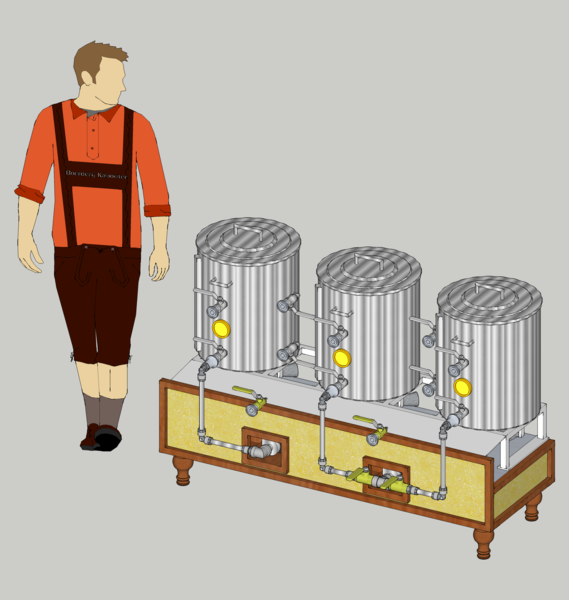
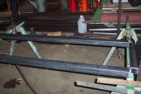
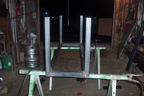
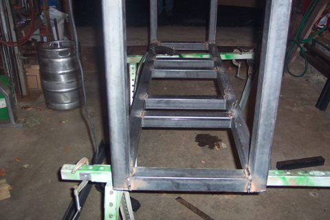
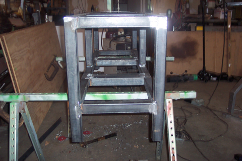
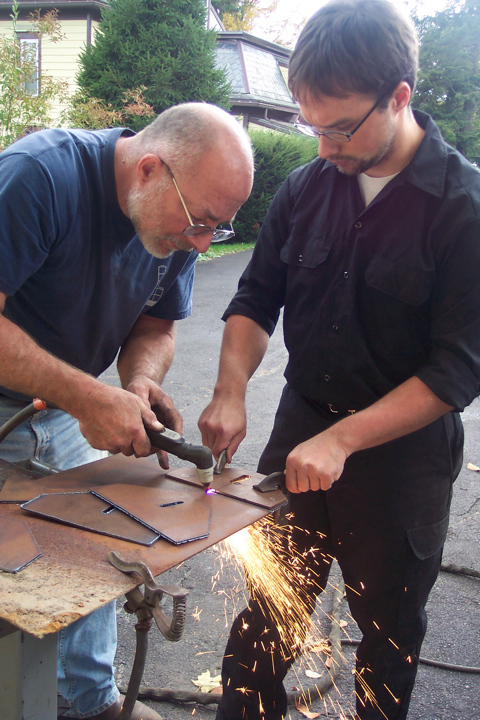
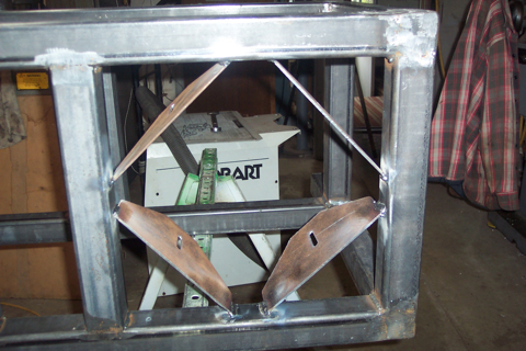
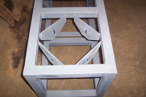
I have no idea how many elephants this stand will be able to hold... I do know that they guy welding this will though! So I am giving him this design and he can make the final decisions as to what support pieces we need and where. I took out the two completely unnecessary supports that were in to top middle sections.

Here is the result...

stand4.jpg


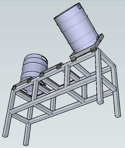
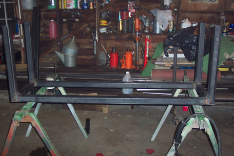
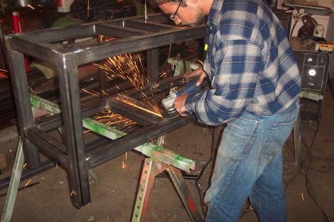
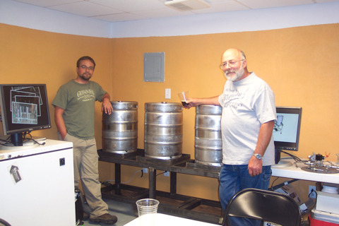
As far as storage space, Maybe some tools/spare parts/fittings while in use but I dont want to use it for regular storage. Might lower the stand even more so that the kegs are easier to get at. Definitely putting casters on (not shown).

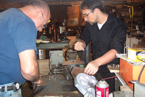
The pumps will mount somewhere under similar to the brutus. Again, I am planning on handing the welder one of the pumps and saying... have fun. I dont think we can mount ours as close as the brutus though due to the fittings and valves that need to be connected. Headed home now to pick up the burners(NB order has arrived!) and give everything to the welder!
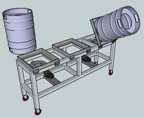
 
Wow my friend, I have to say that I do not like your tippy dumps in this direction. Brutus will not support your kegs this way. It will flip over! I am not sure if your intentions are to maybe tip a pot and rest it on a can or something, but this configuration is inviting something bad to happen. This is a reason that I didn't include it in my Brutus design...
 
I'm fairly certain they will work. I saw in person a 55g drum configured very similar to this which operated with no problem. I figured that if two are up and one is down, that should be enough weight to counter balance everything. Most of the time the kegs will be empty and this is just an easier way to tip them to clean them out. The mash tun is the only one that would have any weight inside of it.

I found some casters on McMaster that we will be ordering shortly.

Casters
Caster Inserts

I further re drew the model to make it look more like the brutus as we no longer need the excessive supports. The height has been altered to 24" per leg + 5" for the caster. (this was so we could more easily cut up one bar into 4 legs) and some similar things were done with the length, shortening it from 5.5' to 5.4' to make a 5' section work for all of the longest cross beams. The design only uses pieces of 3 different sizes. The third size is directly related to the size of the tippy frames once they are fitted to the kegs. Those size pieces will make up all of the supporting pieces.

A few things we changed, hopefully for the better.... The pumps are moved under the burners so that the center of the pump head is in the center of the stand. Their will be a shield between the burner and the pumps of course. This will allow us to more easily run the tubing without it running into itsself or things catching on it. It also allows us to put some sheet metal in the front with our logo on it to dress things up a little and make it a little nicer to look at.

stand6.jpg

And thats where we have things set right now. if anyone has some suggestions, like what would make our tippy dump better and not fall over, or how to shield the pumps etc then let us know.
 
That sounds like a lot of work for something that is really just an added convenience. I think connections and connectors will be too cluttered with an A frame design.

It is the same design as beerthirty's (yes I know his is more stable)
DSCN2363.JPG


Also, we could make the left and right kegs dump left and right instead of towards the front and only the mlt in the middle would flip frontward. That should make it more stable.
 
I wouldn't worry about the tippy-dumps. Worse-comes-to-worst just stick a saw-horse under the mash when emptying it out. You don't need to pass OSHA codes or whatever.

Also, I finally got around to updating my pump sketch. If you download my new one it is accurately dimensioned.

That stand and the height look much better to me.

Another sketchup tip: I modified the person that shows up to be my height and dimensions. That way I can put myself into my drawings and get a better feel for size and space. For example:

Brewery.png
 
I think I still have an older version of that drawing. You have tri-clovers in this one. I cant find those in the 3d warehouse. Can you send me your sketchup file? I would love to start sketching out some of the parts. Also, I only saw the one march pump you did with the inlet in the front and outlet going up. We have the one with left and right in/out. I saw another model done by someone else that shows this model. Have you updated yours since then?

Also, does anyone have a how-to on coiling SS tubing?
 
You could move the pivot points to the ends for the outside keggles. This would give more stability to the frame when tipping. I would also make the mlt one of the outside keggles since that is the most dangerous to dump due to the weight and heat of the spent grains. The HLT and BK are normally empty and only tipped for cleaning.
 
A few of us made it up to Utica to visit the F.X. Matt brewing company, better known for Saranac and Utica Club but also now contract brew for boston and pete's wicked ale. It was a good time. Our welder was away for the weekend and we hope that he will begin working on welding the brew stand today! Also picked up a few of those white plastic folding tables from Sams Club. These will be our work benches to put sanitized equipment. We can easily clean them and they look to be built well. Also, I was able to put a few coats of paint on the kegerator to touch up all of the scratches and other marks created while drilling the shank holes. Soon, the kegerator will be complete!

Still shopping around for a 12" SS lid. It's quite a bit harder than you would think. most stuff sold is crap or only sold with pots and pans. How can they sell so many pans without lids and then not sell any lids seperate??? Might have to switch to glass or something. We need to have lids in hand asap so we can give them to the welder to cut up the kegs. Any suggestions? Walmart/target etc is about all we can come up with.
 
I also wanted SS lids. I had a tough time finding a place that will sell just lids. I found the easiest way to get Stainless lids would be to buy a skillet with a lid I like and use the lid.

I ended up going to a restaurant supply store and going with Aluminum lids. They are cheaper and readily available. I figure I'll probably make changes and the cheaper ones will be easier to replace.


I also considered glass. Trouble is with a Brutus system you will have to drill it.
 
Inching closer to the party this weekend. Still lots left to do. Talked to our welder Adam, he says he is ordering the steel tubing today, it will arrive tomorrow, he will have it welded, sanded, and painted by friday.... that sounds impressive.

Looks like we wont have the keggles ready for the party though as we cant find a good SS lid. Going to have to order them online in the future. We did order the casters though, so those should be ready to snap on when the frame arrives.

A short video, and what will later be a podcast, is being edited from video we shot inside and outside the brewery. We will be shooting some video of the party and tastings etc to roll into the video before it is released as a podcast.

We might not get around to posting updates on the parts and assembly right away but we plan on posting pictures of everything as soon as the party is over this weekend.
 
we spent the last few days working on our kegerator... I couldnt resist posting pictures here. Going to start a new thread later that shows the entire build process...

After what feels like forever, our kegerator is complete, just in time for our first party! Here is a picture of it in the brewery.

kegerator1.jpg


It can hold 5x corny kegs (5gal each) or one 1/2bbl keg and 1 corny. 4 taps, (tap handles are not yet done) We managed to do something I dont believe has been done before. We integrated the tap handles directly into the lid instead of building a separate wood collar. Here is a closer look at the inside.

kegerator2.jpg


You can see the 4 kegs connected. here, a board is propping up the lid right now as the weight is too much for the spring to handle. We will have to replace it.The origonal lid and seal are still intact. In the back you can see the gas line coming in. The black squares are cutouts in the lid where the taps are installed and the beer lines can come in. Plastic clips keep the hoses out of the way so that removing and installing kegs is much easier.

kegerator3.jpg


These are the two Micromatic secondary regulators for pressurizing the kegs. They were a little pricey but worth every penny as the knobs easily adjust. We used two regulators for a variety of reasons. One, is that we could use the kegerator to force carb two kegs while using the second regulator to serve two kegs. Another is we could connect a bottle filler to bottle beer directly from the keg. In the small container between the gauges is the temperature probe for our temperature control circuit we built. Suspending it in a small container of water gives us liquid temperature inside the kegerator instead of air temperature, much more accurate.

kegerator4.jpg


A hole in the rear of the lid and a few rubber gromets lets the CO2 line in. Using a special quick disconnect we can easily disconnect the CO2 supply.


kegerator5.jpg


There is our temperature control circuit in operation. The read light tells us it is too hot, the yellow says the compressor is on. The temperature sensor wire is in gray in the picture. The other wire is connected to a solid state relay turning on the compressor.

kegerator6.jpg


And here is a close up shot of the lid. This is showing the back side of the taps and how we can easily access them to remove them for cleaning.

Everything is ready to go and the beer is chilling. It wont be long before our new kegerator is put to the test serving 20 gallons of our beer!
 
Very nice setup you have drawn up here - gonna probably use alot of this when I'm ready to prototype my own system.

You ever consider the BCS-460 for your control and automation?
 
I'm impressed with the progress you've made in such a short time!

It doesn't sound like you are interested in proportional control of your flow during sparge. But earlier there was some discussion about it and I thought about an ultrasonic level indicator that is often used by home automation nuts (my other money-draining addiction.)

The Maxbotix Ultrasonic level sensor is relatively cheap (between $25 and $90) and people report good success using them to measure water levels in things like irrigation tanks.

Even if it isn't useful for your build, I thought someone might use one in another build.
 
Take a look at the LLE Series liquid level sensors by Honeywell.
They are a LED and photo-transistor system that come in plastic or stainless 1/2". Suppy voltage from 5 to 12 VDC. I was thinking about one with a time delay to maintain the liquid above the mash during full time pump circulation.
They can operate from -40 to 257*F, operate off 15mA.
The only added item I would add that would need to be readjusted for each new mash would be the 8 pin electronic timer control knob to a rate of drop that your liquid level above the grain bed lowers at due to different grain amounts, crush amount plus the different filtering flow rates of your mash. As the level lowers less pressure of the liquid above the grain will slow this flow rate down hence a self tending liquid level once the timer is adjusted. I have a collection of IDEC Electronic Timer type RTE-P11, 120 volt 120/240 VAC contact rating with the adjusting knob and mini switches for a range of 1 sec to 10 hr. Two sets of NO & NC contacts plus the power.
SquareD is another 8 pin timer #9050 JCK16V20, 0.1-10 minutes but only has a min to max adjusting knob. Also rated 1/3 HP 120 volt contacts NO, NC in the collection from a job site.
My plan is keep collecting parts as this will work with the BCS 460 I already have.

Using a couple used LM34 temp probes operated from 5 to 30 VDC with less than a 90uA current drain a cube power supply or a 9 volt battery will supply it with a digital meter for internal deep well fermentation readings. This will free up my BCS 460 on the brew stand as a single unit at one house with the fermenters at another house. Ideas to think about for your future build.
 
Brewbeemer,
Will those LLE Series liquid level sensors be accurate enough to read volumes to the quart/litre, or just accurate enough to maintain a general amount of liquid above the mash?
 
We held our tasting party this weekend and the turnout was great, the weather , however, was not. It begain raining as soon as the party started. That did not detour people from kicking 3/4 of our kegs! We are still uploading pictures from the party and adding up info from the surveys. We have about 40-50 for each of the beers we served.

Our welder, Adam, came through with a nearly complete brew stand only minutes before the party began. Here are some pictures of him welding the stand together. He promptly took it back to finish up mounts etc and paint it.

More pictures and progress coming soon now that the tasting party is over.

weld1.jpg


weld3.jpg


weld4.jpg


weld5.jpg


weld6.jpg


weld7.jpg


weld8.jpg


weld9.jpg


weld10.jpg


weld11.jpg
 
Trying to figure out what stuff we still need to complete our brewing system. Hope to test out some of the hardware/software tonight. We need barbed TC fittings and silicon tubing. Need some plumbing odds and ends for hooking the gas up. Need new O-rings for the lock nuts. We need 3 SS lids asap. Need to construct a mill cart at some point before we brew. Thats about all I can think of... I'm sure we are missing something....
 
Trying to figure out what stuff we still need to complete our brewing system. Hope to test out some of the hardware/software tonight. We need barbed TC fittings and silicon tubing. Need some plumbing odds and ends for hooking the gas up. Need new O-rings for the lock nuts. We need 3 SS lids asap. Need to construct a mill cart at some point before we brew. Thats about all I can think of... I'm sure we are missing something....

It's called extra cash, never enough and fun time brewing learning your new brewing system is what's missing. Looking good bet the pressure was on with your welder, hate being pressed for time when welding.

Once chased cracks Tig welding a 72 BSA gas tank that had sharp edges like an old 350 Honda tank of the early 70's era. The tank owner and 3 my friends hovering over my shoulders whole Tig welding paper thin steel. Had at the end 11" of welding, dressing with flap wheel, brown primer then adding solvent looking for dark damp spots in the primer then Tig some more. Friends always in a hurry hovering. In a hurry stick a tungsten makes for a cranky welder.

I was told that VHT automotive paint rated to 1,200*F for exhausts will be off the market soon, anyone else hear about this? Tet another attack by the EPA?
 
Talked to our welder again today. He is finishing up the mounts for the burners etc and putting on the hinges for the dump system. After that its being ground down again and primed and painted with hi temp paint. It should be done by next weekend. We ordered some SS lids from Sears which should be here by then. When he drops off the completed stand we will give him our kegs + lids to cut up. I think we may end up drilling the holes in the sides our self but we will see.

More pictures of the build process when we get them.
 
search sears and walmart for stainless steel lid and you will find them. I think they both carry the same brand. Ordering online from a sears store means free shipping to your house...

A quick question.....

We are planing on having a proper analog control panel for manual control over everything while we are building the automated aspect and for other purposes like cleaning etc. So the basic concept is this, every *thing* (valve, pump, etc) is controlled via relay via a 5v dc signal to switch either 12vdc, 24vac, or 120vac to the device that wants to be turned on. We are going to therefore build a relay board or two that will manage these connections from Micro Controller -> relays -> valves But we are going to also hijack the abilities of the relays so that we can either manually trigger the relay with a switch or with the micro controller. With that in mind here is a picture of what the control panel might look like....

panel.png


The colored circles represent LED's and the colored squares represent toggle switches with different colored missile style safety covers. The outside of the cover would be painted or labeled to indicate which thing the switch controls. The LEDs would light up on the board regardless of if the manual switch or the micro controller triggered the device to turn on. In this way we can know that, for example, our pump is not plugged in or burnt out but the relay is working etc.

so question is....

What do you think about this idea?

and... we want to connect everything up in such a way that it can all be taken apart and put back together for cleaning etc and everything has nice wiring and plugs etc. So that means that each valve needs a 2 conductor plug on it and a patch cable to connect valve6 to connector 6 on the relay board. I was thinking of water proof automotive connectors or something along those lines. Does anyone have a suggestion for waterproof connectors that we could use for this purpose?
 
I’m not sure if I completely understand what you’re trying to do here. Are you looking to:

A: Have the Micro controller drive everything, and by adding manual control really just add toggle switches as inputs to the Micro controller and then have the Micro controller coded to know what to do with these inputs?

B: Wire all the *things* independent from the Micro controller directly to toggle switches?

I apologize if I’m completely missing what you’re saying, but I’m struggling with this concept myself right now. Option A seems more appealing to me because programming makes far more sense to me than wiring, but then I have a single point of failure if the Micro controller I’m using dies.

The issue really comes down to I’d like to have the my manual controls override my programmed controls, and can’t figure out a way to accomplish this without wiring everything twice and having a control toggle switch for manual or automated control.
 
Brewbeemer,
Will those LLE Series liquid level sensors be accurate enough to read volumes to the quart/litre, or just accurate enough to maintain a general amount of liquid above the mash?

These sensors will not give you an output corresponding to the amount of liquid present. They will only detect if there is a liquid present or not.

From the Honeywell LLE Series Liquid level Sensors Data sheet:

http://stevenengineering.com/tech_support/PDFs/31LIQUID.pdf

DESCRIPTION
The enhanced series of liquid level sensors incorporates a photo-transistor trigger which provides a digital output that denotes the presence or absence of liquid. The mode of operation is derived from the principle of total internal reflection. An LED and photo-transistor are housed within a plastic dome at the head of the device. When no liquid is present, light from the LED is internally reflected from the dome to the photo-transistor. When liquid covers the dome, the effective refractive index at the dome-liquid boundary changes, allowing some light from the LED to escape. Thus the amount of light received by the phototransistor is reduced and the output switches, indicating the presence of liquid. This method of liquid level sensing is very fast, and almost instantaneous for water.

This sensor http://www.automatedsonix.com/son50.htm may be for of what you are looking for. It puts out a current proportional to the volume of fluid in a tank or has a RS-232 direct connection to a computer.
 
I really think the MPX5010 pressure sensor from Freescale is the way to go for this. I have yet to test it, but this is what I plan to use to measure volume. You'll need to create an initial look-up table to convert voltage input to height to volume, but you'd only need to do that once. If you had a uniform shaped kettle, keggle's not going to be uniform, you could just write a formula to use on the fly.

The issue is in the MLT you're never going to get an accurate reading for volume as the displacement from the grains will make measuring volume inaccurate. I was hoping to use one of these in the MLT to tell if there was liquid under the grain bed and thus how fast or slow I needed to run the pump.

The following datasheet and white paper helped me understand a great deal of this.

http://www.freescale.com/files/sensors/doc/app_note/AN1516.pdf

http://datasheet.digchip.com/311/311-3-099693-MPX5010.pdf
 
using a sensor I thought of one way to measure water in the MLT.... Water in HLT before transfer to MLT - water in HLT after transfer to MLT = water in MLT.... throw in evaporation rate and grain absorption etc.

About the switches.... it goes Micro controller ---5v--->relay---->device but instead of just the micro controller output connected to the relay, also connect a switch that can throw 5v at the relay. put some diodes on it to protect everything and now the relay can be activated by either a manual switch or micro controller. In this way less wires are taken up on the micro controller for each switch etc going in and if the micro fails or is doing something else, the system can have manual over ride while it continues to do whatever.

While teaching the micro controller to brew we can use the manual controls to activate valves etc to begin brewing before its fully automated too.
 
FWIW,
Here is a wet sensor for level measurement that could be used for level control http://cgi.ebay.com/NEW-LEVEL-MASTER-SENSOR-PRESSURE-TRANSDUCER-TRANSMITTER_W0QQitemZ290348023551QQcmdZViewItemQQptZLH_DefaultDomain_0?hash=item439a173eff&_trksid=p3286.c0.m14, plastic body would need to be mounted on tubing a couple inches away from the heat of the mash tun. Here is the MSI cut sheet for the sensor http://www.meas-spec.com/downloads/LM_Series.pdf, the unit on Ebay is 0-2 psi (0-54") range.
 
Without going with all the above units I also thinking about those two probe continuity probe sensors one short leg one long leg. This for the low level pump shut off with another unit set higher with the same probes or with both electrode probes the same length for pump on and off. Adjustable spacings for your desired liquid depth above the mash plus made adjustable the whole assembly to your different mash volumes. Easy to clean, simple and can take being banged around by a mash paddle. Just need the proper controller with contacts for your circulation pump.
 
Without going with all the above units I also thinking about those two probe continuity probe sensors one short leg one long leg.

I use the same setup with three probes to fill my brewing water tank.
Only two of the three probes shown, number three is behind pipe.

300L_Water_Tank_Sensors.jpg


Cheers,
ClaudiusB
 
This looks pretty cool. It will read out in gallons or liters. The resolution has a little to be desired but at $125 from Digikey it is worth considering. The down side for those who plan to automate is that it has no input or output for automation.

http://www.ssitechnologies.com/FT_DIG.html

Digital%20Fluid-trac%20Barrel%20Level%20Sensor.JPG

Sawdustguy; you might be onto something here, check a little deeper on the Digi-Trac with their 2 wire and 3 wire connected non contact liquid level sensors. Then can be used to build a automated system. They are located around the world as well the US and the next area code from my location. Prices would be the question. The 2 wire is a voltage output unit of .5 to 4.5 volts, with a input 10-32 VDC. The 3 wire a resitive output current sink 20-200mA. Both ultra sonic units accurate to plus or minus .125". Maybe bull8042 will chime in on these units? This may be a double reply I didn't see the first one posted.
 
The stand is welded, painted, and complete. The burners and pumps are being mounted and its going to be delivered later tonight. We will pop the wheels on it and take pictures to post asap. It took us some time to order the lids and actually get them in. The kegs will be modded next. Now that we have the stand done it will be much easier to figure out where to drill the wholes. Stay tuned for some pictures later.
 
Random snow all weekend means we cant take delivery of the frame yet due to traveling in bad weather. Progress is still being made however, the welder has all of the parts and is now cutting the kegs up to fit the lids on and holes to bolt the kegs to the frame. We are told the hinges for the dump system are pop riveted on and can be drilled out to replace with larger "baskets" to hold larger vessels in the future. We are pretty excited about that.

Still working on the electrical side of things. Due to the design of the 12v pumps we have, we may be able to very easily modify them to a standardized plug format of some kind. We were thinking of using the "barrel" style connector found on most electronics used for power. We could put flush mount female connectors in both the pumps and the control box and use male-male jumper cables to connect the pumps to the control panel. We want to be able to remove all wires from both the control panel and pumps so we can move or work on them or clean them. Twisting off a pump threaded onto a pot will be very annoying if it has a wire attached.

For the digital temperature sensors we will be using stereo phono (headphone) jacks. They are already well made and put together where the temperature probe meets the hi-temp wire, its just a matter of putting a simple jack on the end.

A few other connectors need to be worked out still. The pumps have standard AC plugs on them already, it will be easiest to continue to use standard AC plugs for this purpose, even though they look crappy. We need connectors for the gas valves which are 24vac. The connectors on the valves themselves are the spade type, I am assuming we could use the same "barrel" style connector with the right gauge wire for 24vac and it would work fine as well.

We are still working out how the electronics will be laid out. Everything is either going in one big box or things will be separated out into relay boards/power supplies and the controller hardware with something like a serial cable connecting the two.

If anyone has suggestions on what type of connectors to use we would love to hear them! everything is 2 or 3 conductor. Waterproof would be nice but we haven't found anything reasonable in waterproof.
 
What PWM controller are you planning to use, and with what motors? I've been looking around MarchPump, but am unsure what motor I want to go with as most of the PWMs I'm finding want 12 or 24v.
 
Here is a quick picture of the current idea for how to lay out the electronics and connections. 3 separate boxes, a control box with the arduino micro controller, manual switches, LCD screen, buttons. A box that all the valves + sensors plug into that is mounted on the underside of the frame. And a third box that does all of the AC conversions and holds the hotter SSR relays for the 24v and 120v going to the gas valves and pumps. This way we can leave the two boxes mounted to the system and then plug and move the control box wherever we need it.

Control.png


Suggestions?
 
We had our brew stand delivered last night while we were brewing a pale ale. We have tons of pictures to share but it looks like it may take a few post to do it. So lets start with the pictures where we last left off when the brew stand was half finished for the party.

Here is our two welders/machinists that worked on the stand.
weld12.jpg


They then brought back the stand to their shop after the party and kept working on some of the details. Here they are cutting the heat shields/burner mounts with a plasma torch.
weld13.jpg


Welded mounts in place
weld14.jpg


Fabrication of mounts
weld15.jpg


Burner with mounts attached
weld16.jpg


Welded to the frame
weld17.jpg


Their welder acted up at the end and they wound up stick welding the remaining supports.
weld18.jpg


Primer
weld19.jpg


More primer
weld20.jpg


Even more primer
weld21.jpg
 
Back
Top