Help modifying diagram for 2 power inputs

Homebrew Talk - Beer, Wine, Mead, & Cider Brewing Discussion Forum

Help Support Homebrew Talk - Beer, Wine, Mead, & Cider Brewing Discussion Forum:

This site may earn a commission from merchant affiliate links, including eBay, Amazon, and others.

johnp

Well-Known Member
Joined
Jun 23, 2010
Messages
139
Reaction score
8
Location
SD
In another thread I started, I explained that my 220 service has two hots and a ground and no neutral. A couple members suggested I run both my existing 220 and my existing 120 into one control box.

This is the schematic for the panel I'd like to build. As you can see, its got 2 elements, 1 pid, and two pumps, for a 3 vessel, single tier herms. (thanks P-J)

Auberin-wiring1-a4-4500w-30a.jpg


Could any one help modify it for two power inputs? (110v and 220v)

Also, how would i add gfci protection? For the 120 line, would it be best to install a gfci breaker in the main panel? Can my 220 line still be run through a spa panel? If so, how would this diagram be modified for h-h-g?

power-panel-6.jpg


Any help or advice is greatly appreciated!
 
First issue: You are dealing with NEW electrical work. Therefore it must comply with current electrical code. The 3 wire power is indeed 2 hots and a ground (current code).

I suggest that you have an electrician pull new wire for your system (4 wire - black, red, white and ground).

Play it safe, do it right & do not play 'You Bet Your Life!'
 
First issue: You are dealing with NEW electrical work. Therefore it must comply with current electrical code. The 3 wire power is indeed 2 hots and a ground (current code).

What do you mean that they are new? Both the 220 and 120 are already installed and were already installed when I purchased the home in 2008.
 
What do you mean that they are new? Both the 220 and 120 are already installed and were already installed when I purchased the home in 2008.
The wiring is not complete based on the pictures and information you posted. Therefore it is new work and MUST comply with current code when the wiring is completed.
 
Gotcha! Thanks for your help! But your saying my existing h-h-g wiring would work for that spa panel diagram? maybe I was reading that wrong, I thought it was hot-hot-neutral coming from the main panel, in the diagram.
 
Gotcha! Thanks for your help! But your saying my existing h-h-g wiring would work for that spa panel diagram? maybe I was reading that wrong, I thought it was hot-hot-neutral coming from the main panel, in the diagram.
That would have been true if the wiring was completed prior to the changes in the NEC.

The typical dryer (at that time) was a 240V - 120V device. It was powered with a 3 wire circuit (hot, hot & neutral) With todays code a 3 wire circuit for 240V is hot, hot & ground.

New plan different ball game.

Please think this whole thing through. If something goes wrong you are WAY out on the covereage you might think you have.

You only have one chance to do things right.

Be very careful.

P-J
 
P-J, just to clarify: I believe he does have H-H-G for his existing wiring. Does that conform to code if one is using 240V circuits only (no 120V)? If it does not conform to code, then we can ignore the rest.

If it does, then I would think one could wire the spa panel with H-H-G in and H-H-G out, and get GFCI protection. Is that correct?

As to the original questions, your 120V would be a completely separate circuit, and the best way to get GFCI protection is to just get a 120v GFCI outlet at a hardware store, and replace your current wall outlet. Inside your control panel you would need an input for 240v and a separate input for 120v. You would run the 240v H-H-G to your elements, your 120v H-N-G to all of your 120v devices, and and bring all the grounds together the same as you would if you only had one input. Worth a diagram, assuming that there is not a code issue.

Yes. You have it right.

He is welcome to develop a diagram for that application and then be within current code.
 
Yes. You have it right.

He is welcome to develop a diagram for that application and then be within current code.

That was actually my original question, can someone help me modify the control panel diagram I posted, to have two power inputs - 220 for the elements, and 120 for everything else.
 
P-J, just to clarify: I believe he does have H-H-G for his existing wiring. Does that conform to code if one is using 240V circuits only (no 120V)? If it does not conform to code, then we can ignore the rest.

If it does, then I would think one could wire the spa panel with H-H-G in and H-H-G out, and get GFCI protection. Is that correct?

As to the original questions, your 120V would be a completely separate circuit, and the best way to get GFCI protection is to just get a 120v GFCI outlet at a hardware store, and replace your current wall outlet. Inside your control panel you would need an input for 240v and a separate input for 120v. You would run the 240v H-H-G to your elements, your 120v H-N-G to all of your 120v devices, and and bring all the grounds together the same as you would if you only had one input. Worth a diagram, assuming that there is not a code issue.

And thank you for clarifying my original post. I must not have typed it out correctly, but what you said is exactly what I'm after.
 
I am not a diagrammer (nor an electrician), but if you want to take a crack at it I don't think it is that complex. Let's see if I can describe it somewhat clearly:

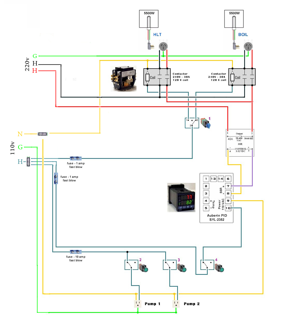
1) Where your 240v feed enters the panel, you don't have a neutral (you have H-H-G), so the yellow lines do not emerge from the 240v feed
2) You will add a 120v feed (from a GFCI outlet), with H-N-G, and the yellow lines will emerge from that neutral
3) You need another color because you have 3 Hots. Most of your devices are 120v, so fewer changes to the diagram if we change the blue H from the 240v feed to black where it really powers a 240v device. So from the 240v feed, change to black 6 lines (1 to each contactor (not the coil), 1 from each contactor to its outlet, and 1 from each outlet to its element)
4) From the 120v feed you added, show your hot as the remaining blue lines, and remove the blue line emerging from the 240v feed
5) For the ground on the 120v feed you added, take the lower green line shown coming out of the 240v feed, and move that so it emerges from the 120v feed
6) You will want to tie both of these grounds together where you connect it to your panel, assuming a metal panel

I think that does it, but you definitely should have someone more qualified bless it before building.

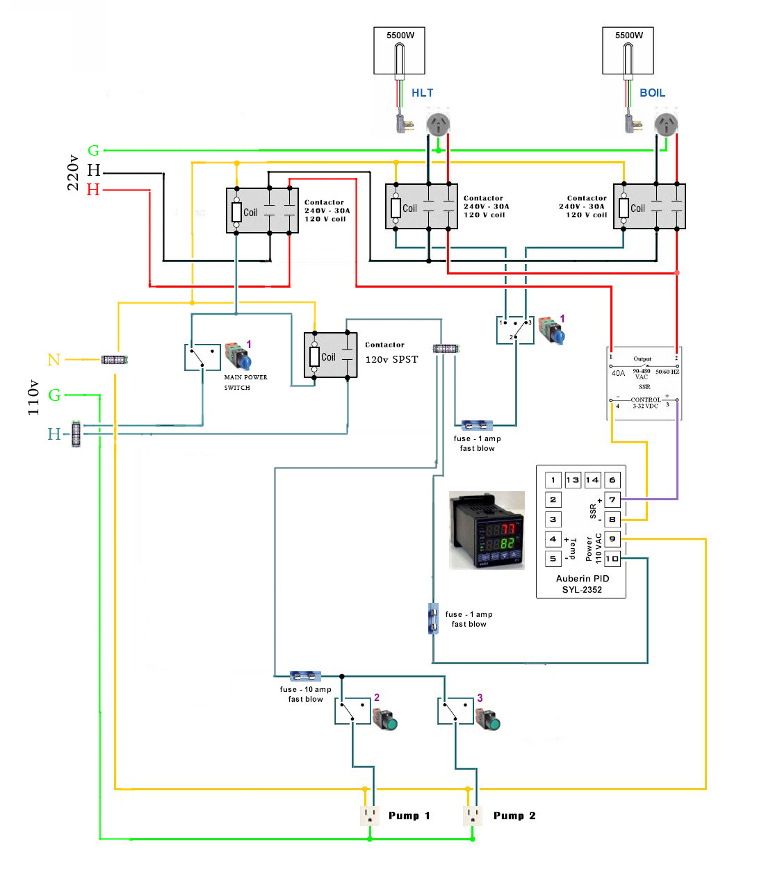
On another note, I would recommend that you have a way to turn off both power feeds in the panel, with a single switch (could be an e-stop switch if you like).

P-J does this with 240v by shunting a bit of current to ground and tripping the GFCI. You would need an equivalent setup for the 120v circuit, but that is way out of my league. In that configuration, hitting the e-stop trips the GFCIs so there is no power to the panel. There are plenty of arguments around that solution, but I will not get into them here.

The other option is to have another contactor, and have the main power switch control the 120v coil, and have the hot lines run through the contactor. In your application (3 hots), you would either need a triple pole, single throw contactor, or you could wire a DPST for the 240v hots and a SPST contactor for the 120v hot, with each coil wired 120v in parallel from the switch. In this configuration, when the switch is closed your contactors allow power to flow into the panel, when the switch is open it is the only thing in the panel that is energized. I favor this solution, and it would also allow you to remove the switch (4) that powers off the PID. The main switch would power up the panel, the PID would be on when the panel is on, and switches (1-3) allow you to control power to the elements and pumps.

I hope that helps.
 
jeffmeh, thank you for the detailed response.

I took a crack at the mods in your first scenario, how does it look?

znsjE.jpg


I'm interested in doing it the way you described in the second scenario though, I just dont have the skill to design that kind of schematic correctly. I took a shot at it but its probably way off. How does this one look?

CwqKB.jpg


As for the spa panel: HHG in, and HHG out, right? How different will the diagram for that be? I posted the original diagram in my OP.
 
I think you nailed it, although as I stated previously you should have someone more knowledgeable than I bless it before moving forward. You do have both switches above labelled "1," but you drew the left one as a two-way switch so it is correct.

For the spa panel, I think it would go like this, in terms of changes to the picture you posted:
1) Change the yellow line entering from the left to green
2) Change the yellow line that goes from there to the grounding bus to green
3) Remove the white pigtail
4) Remove the yellow line emerging from the breaker

As I said, I think that will work, but please have someone else confirm. Good luck.

Edit: Actually, there is no reason to have three ground wires (in from the left to the bar, from the left bar to the right bar, and exiting from the right bar to the right). Just go directly in from the left to right bar, then from the right bar out to the right.
 
Wow. I'm very impressed with your drawing skills.

Good job.

Thanks P-J, does that mean the schematics are correct?

A few questions!

1. Are the red and black wires the only ones that are 10 gauge, and everything else would be 12 gauge?

2. Does there need to be a 1 amp fuse before the main panel switch like there is before the other switches?

3. Is the contactor controlling power to the 220 lines the same as the other two contactors for the elements? http://www.auberins.com/index.php?main_page=product_info&cPath=2_31&products_id=129

4. Can anyone find a link to where I can find a SPST contactor for the 4th contactor?

5. Will all these contactors still fit in this auber enclosure? http://www.auberins.com/index.php?main_page=product_info&cPath=7_34&products_id=143

6. Can the receptacle for the elements be the twist lock kind, instead of the type shown in the diagram? http://www.amazon.com/gp/product/B0...=1789&creative=390957&creativeASIN=B003AUNPG8

That's it for now but I'm sure I'll think of more later.
 
FYI, I edited my last post regarding the spa panel to simplify a bit. Good luck.
 
jeffmeh said:
FYI, I edited my last post regarding the spa panel to simplify a bit. Good luck.

Thanks Jeff.

Can anyone else confirm that the modified schematics are correct? Thanks!
 

Latest posts

Back
Top