Edits/Updates
- Linked up various posts throughout the thread on the build
- Posted the final schematic below
- Posted the Bill of Materials here and in post #60
- Added my "What I would do differently" in post #61
It's time to start the build thread. Inspired by Kal's setup and a bunch of threads here, I've embarked on my own electric brewery upgrade. I've been successfully brewing all grain with an orange cooler and a 10g blichmann over propane for a number of years. The beer has been great. However, the consistency has been sketchy to recreate batches -- mostly mash temps and boil-off rate. Moving to HERMS and electric should address the consistency -- and it's just fun to build stuff. I'm also moving up to 10 gallon capacity.
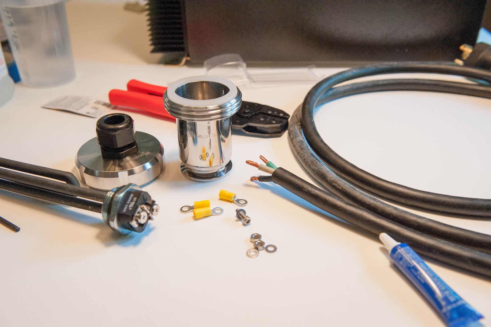
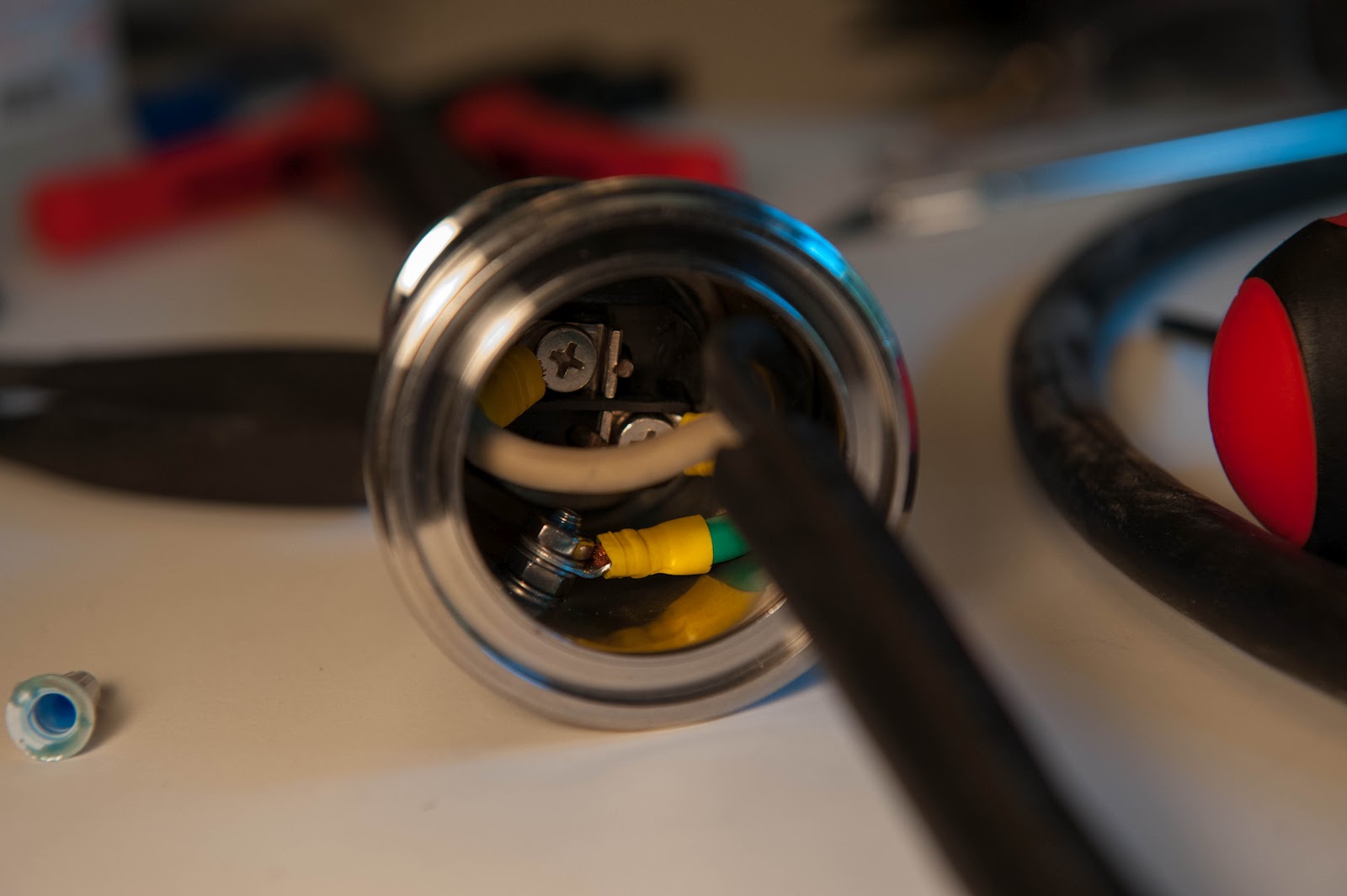
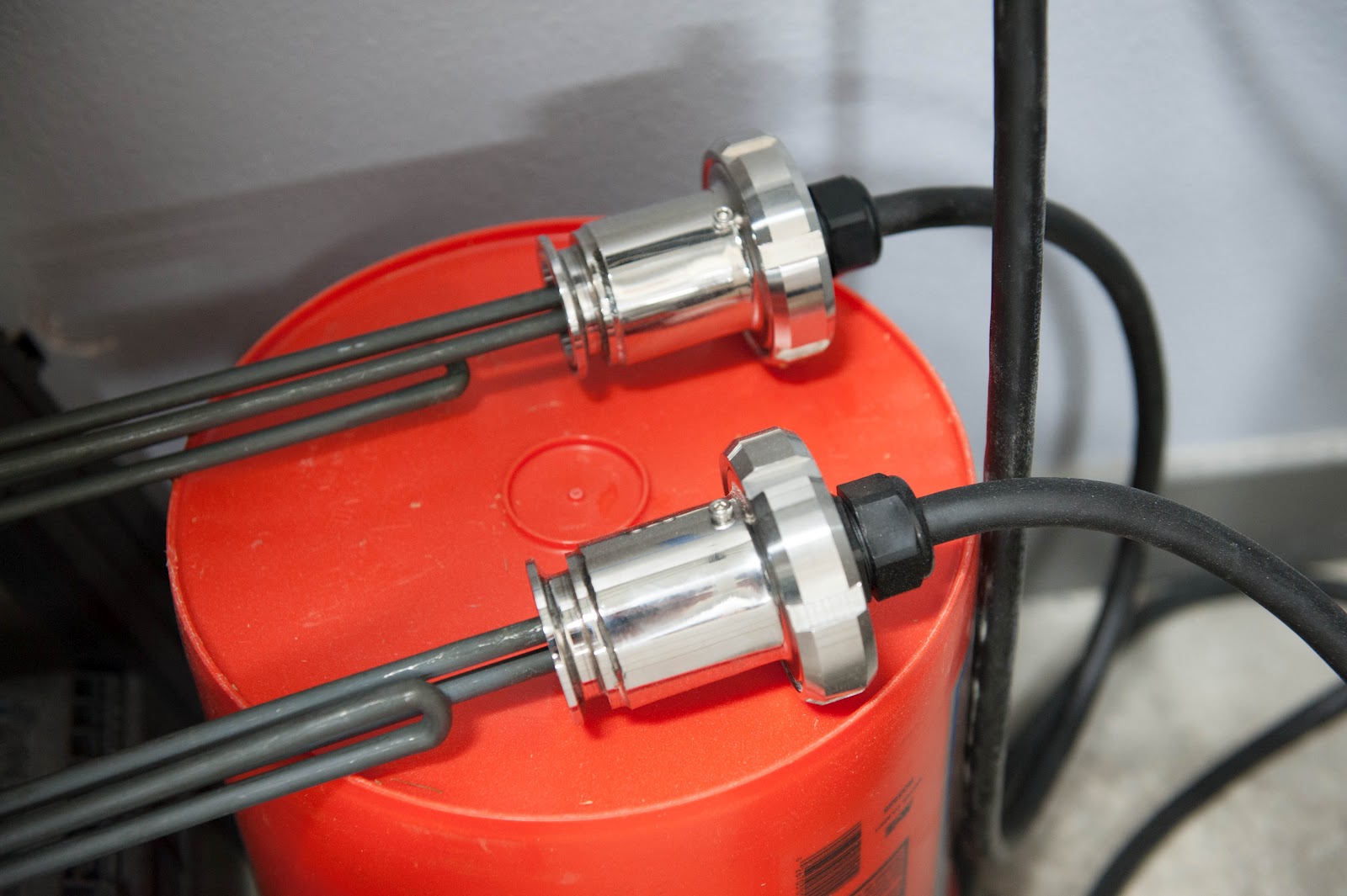
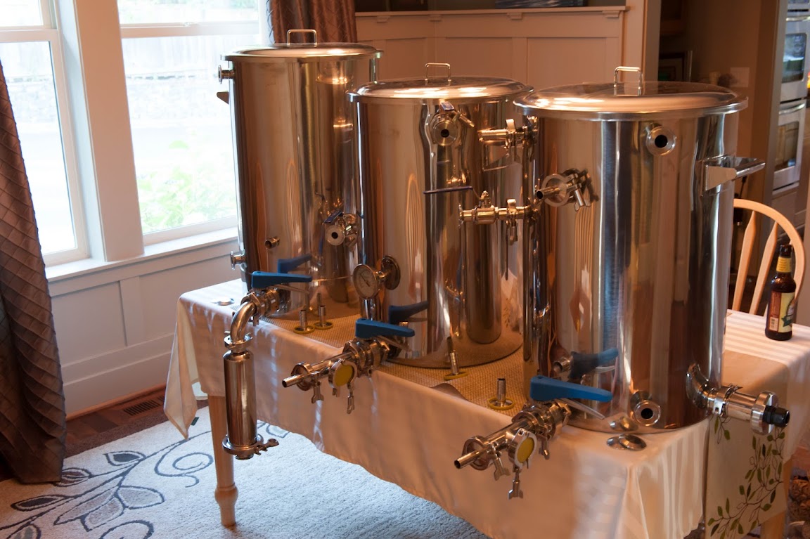
The kettles are finally here, a 20 gallon setup from Stout Tanks with additional fittings for electric elements. I think I have all the control panel parts and my electric permit is in hand to run the new circuits in the garage.
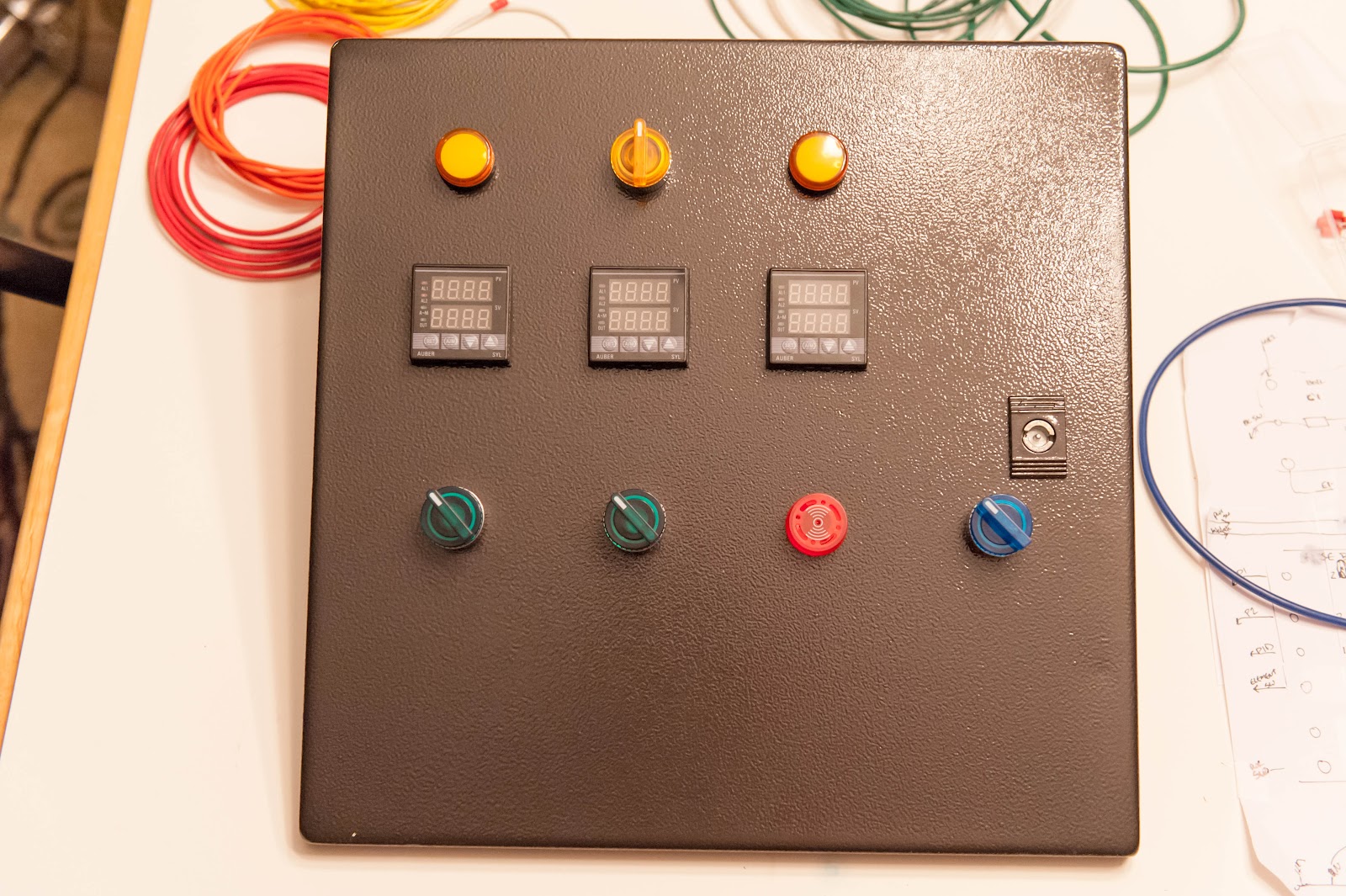
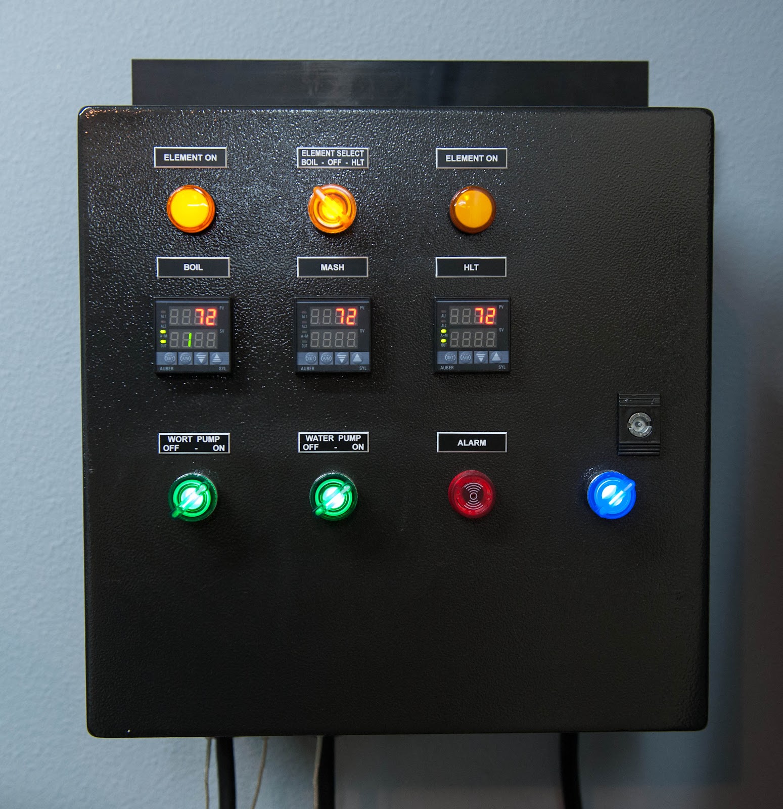
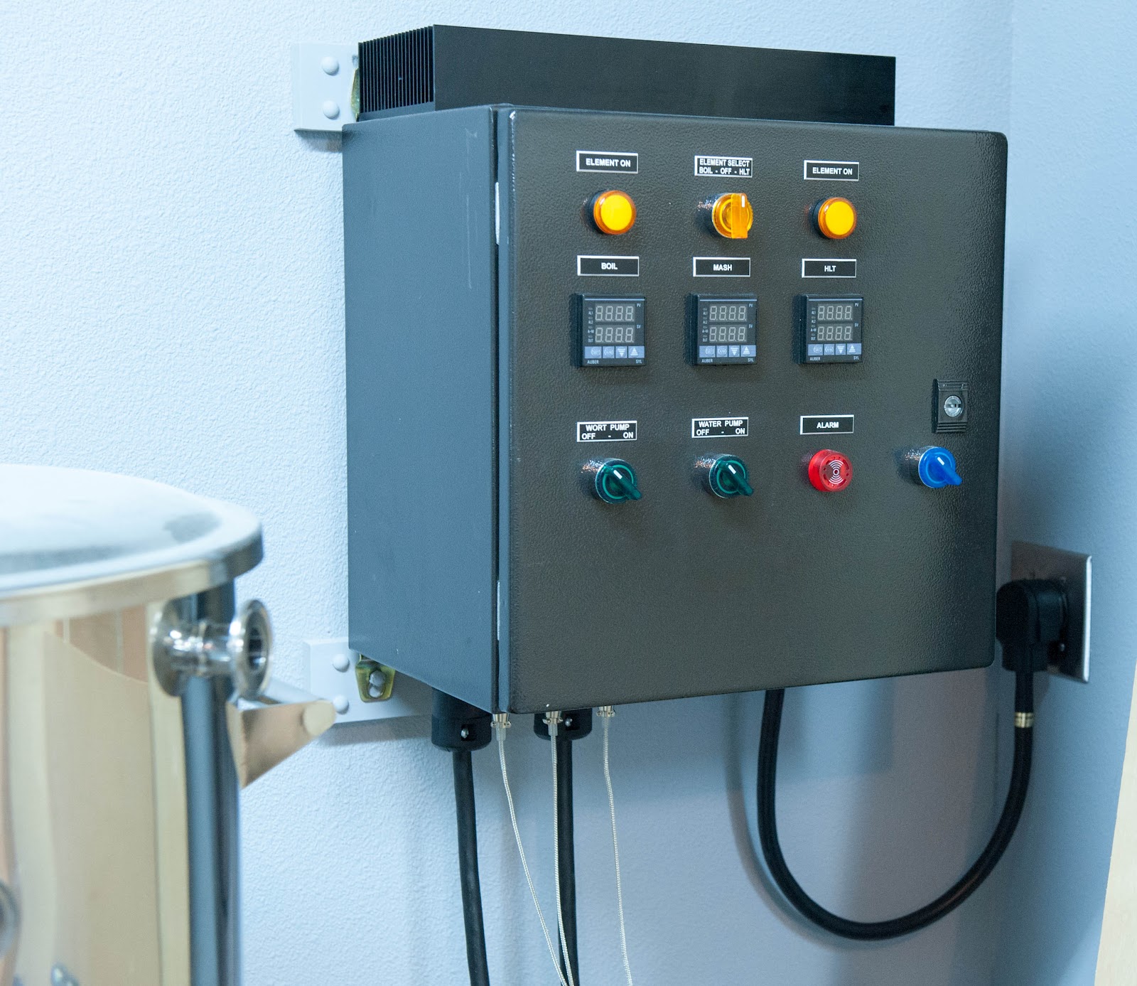
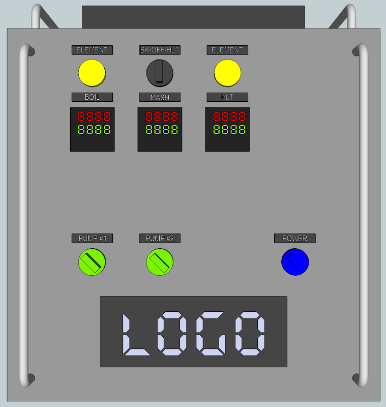
The control panel is a 'light' version of Kal's. I dropped the voltage/amperage meters, the timer and the alarm switches -- but kept all 3 PIDs. I also combined the switches and pilot lights where possible. I have some future plans to switch from the Auber PIDs to Arduino control -- slowly.
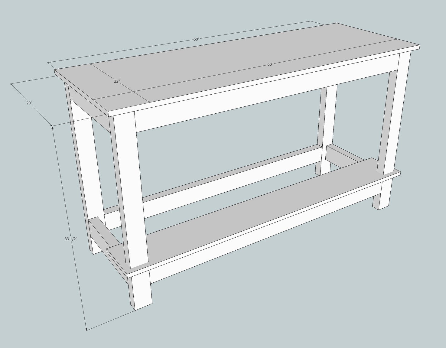
The TODO list isn't too long, but I'll keep a running log of projects here. This includes adding the new circuits (30a and others), the control panel build and the brew space. I've convinced myself I can build a concrete bench/countertop for the kettles; should be fun.
Before...
After...

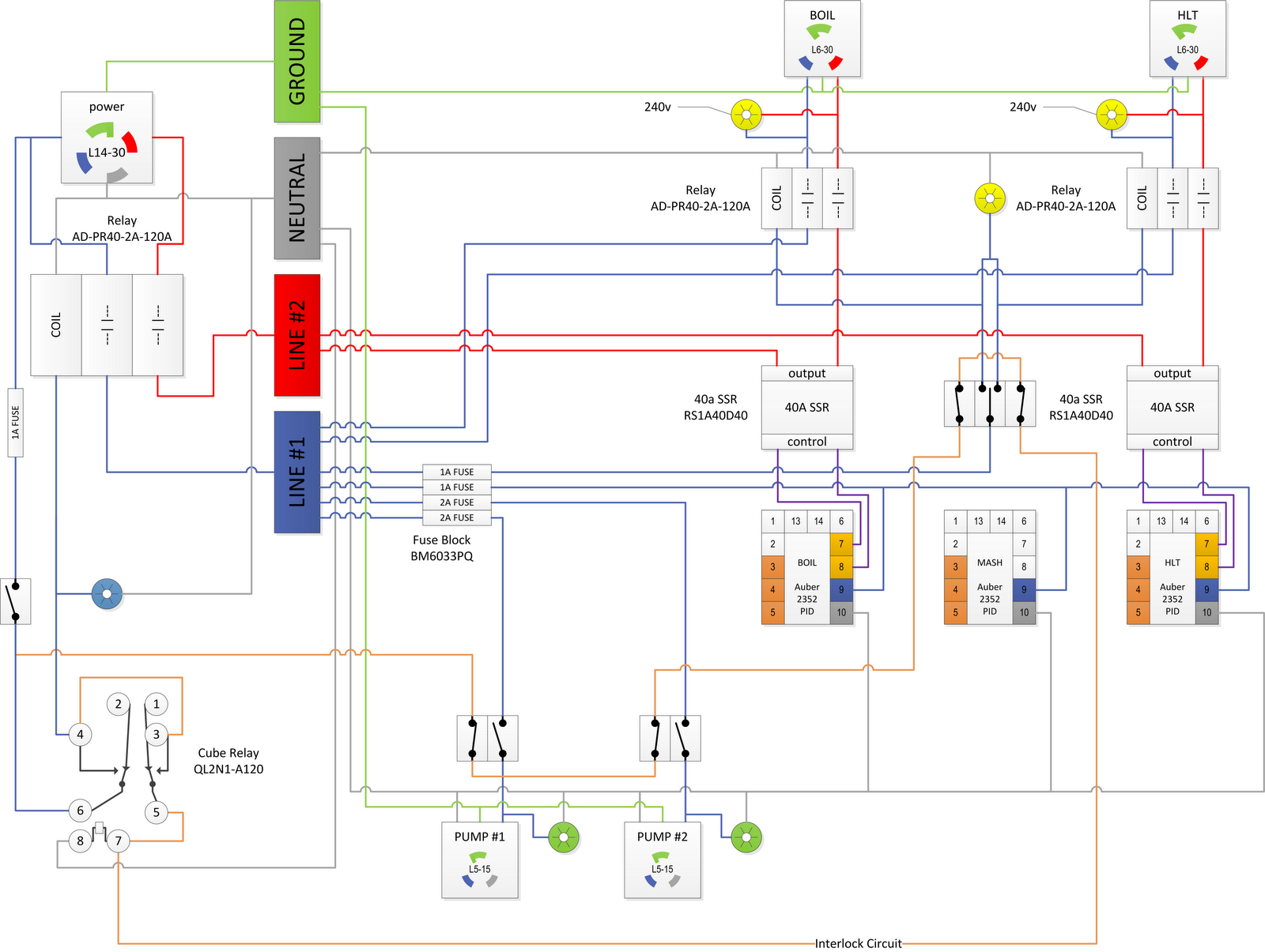
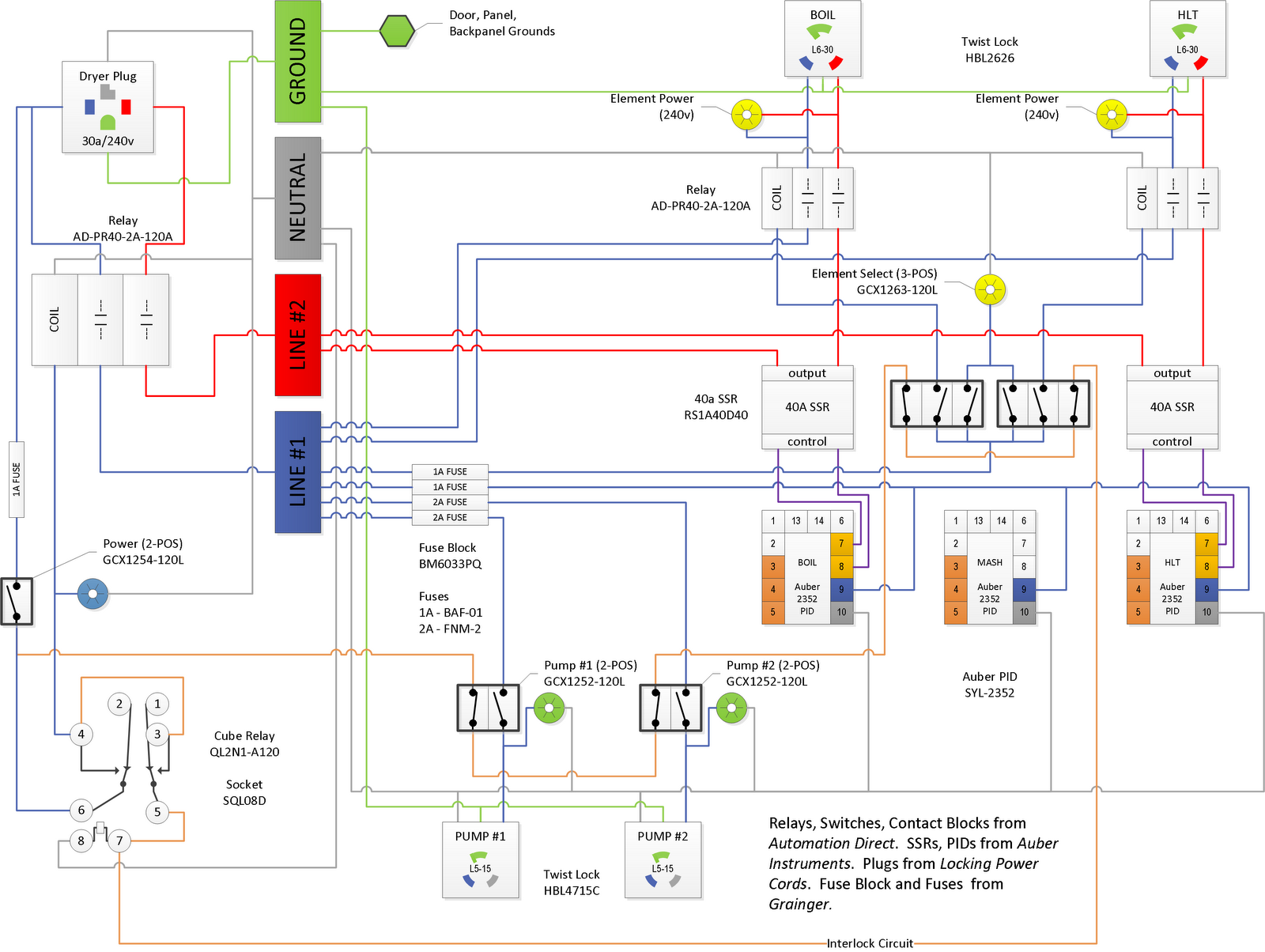
Final Schematic
Available as a PDF or Visio
Bill of Materials
https://www.dropbox.com/s/w1e8w9kr0okyuwp/Parts.xlsx
Commentary in post #60
Build Updates
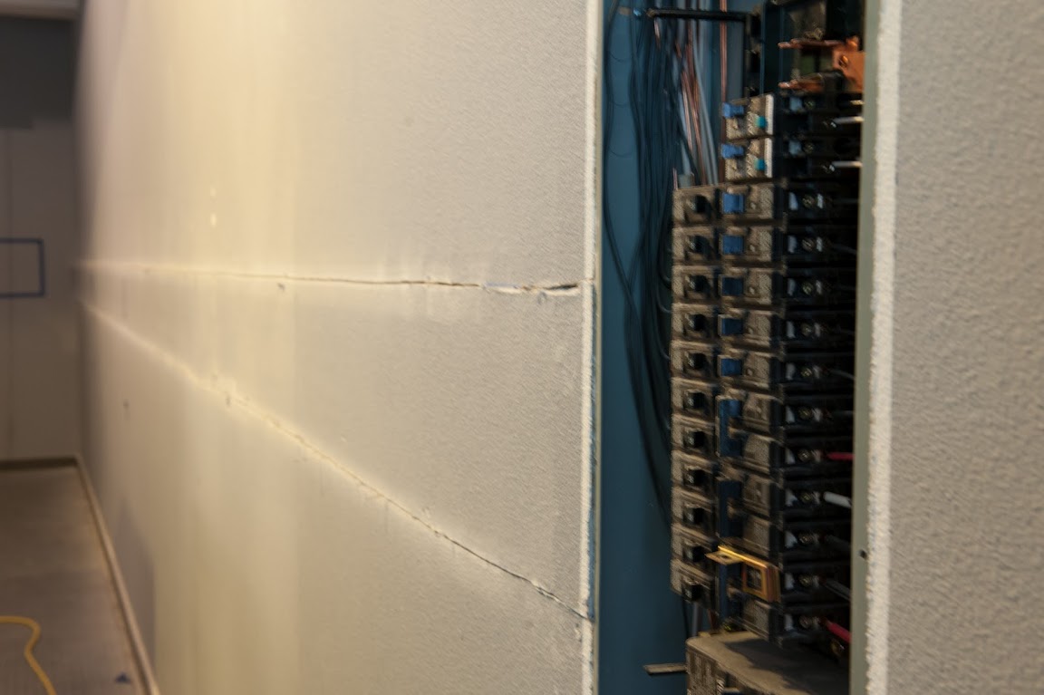
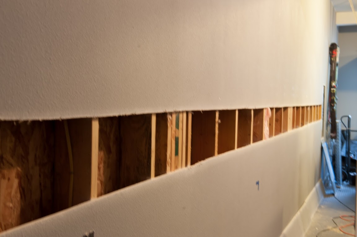
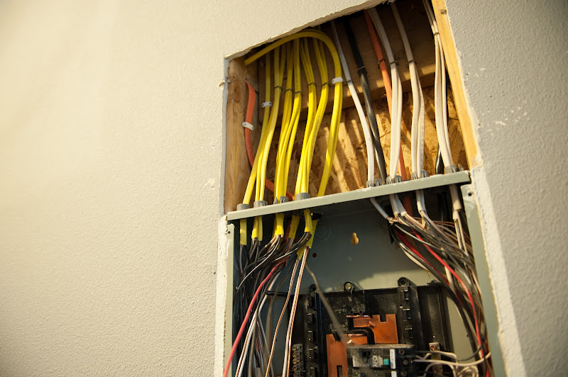
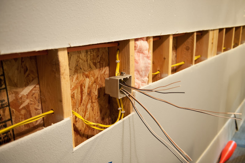
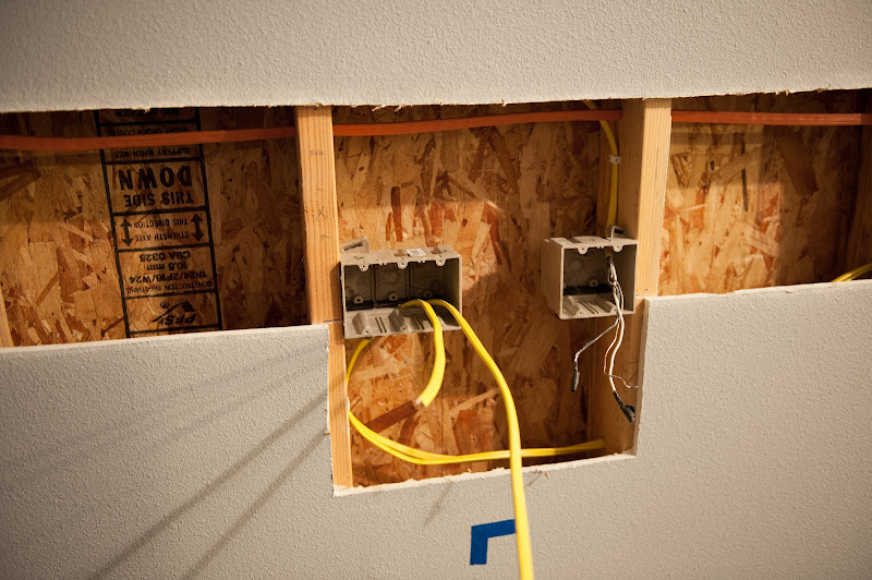
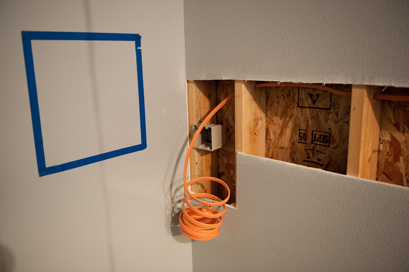
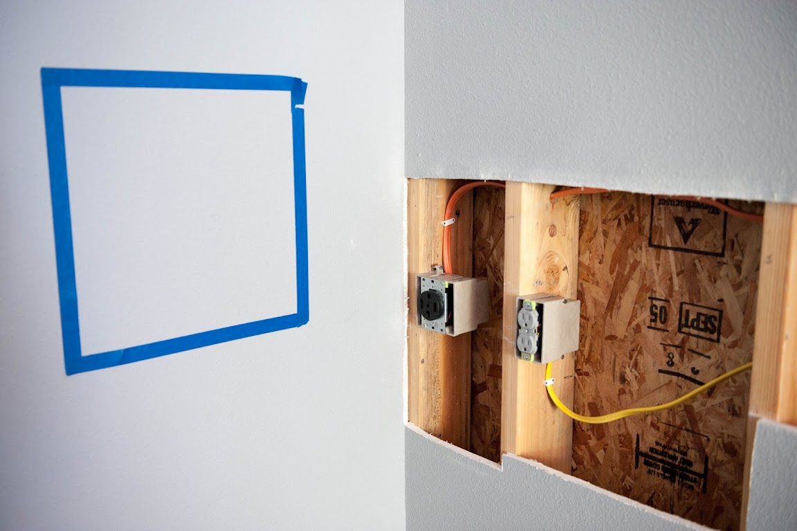
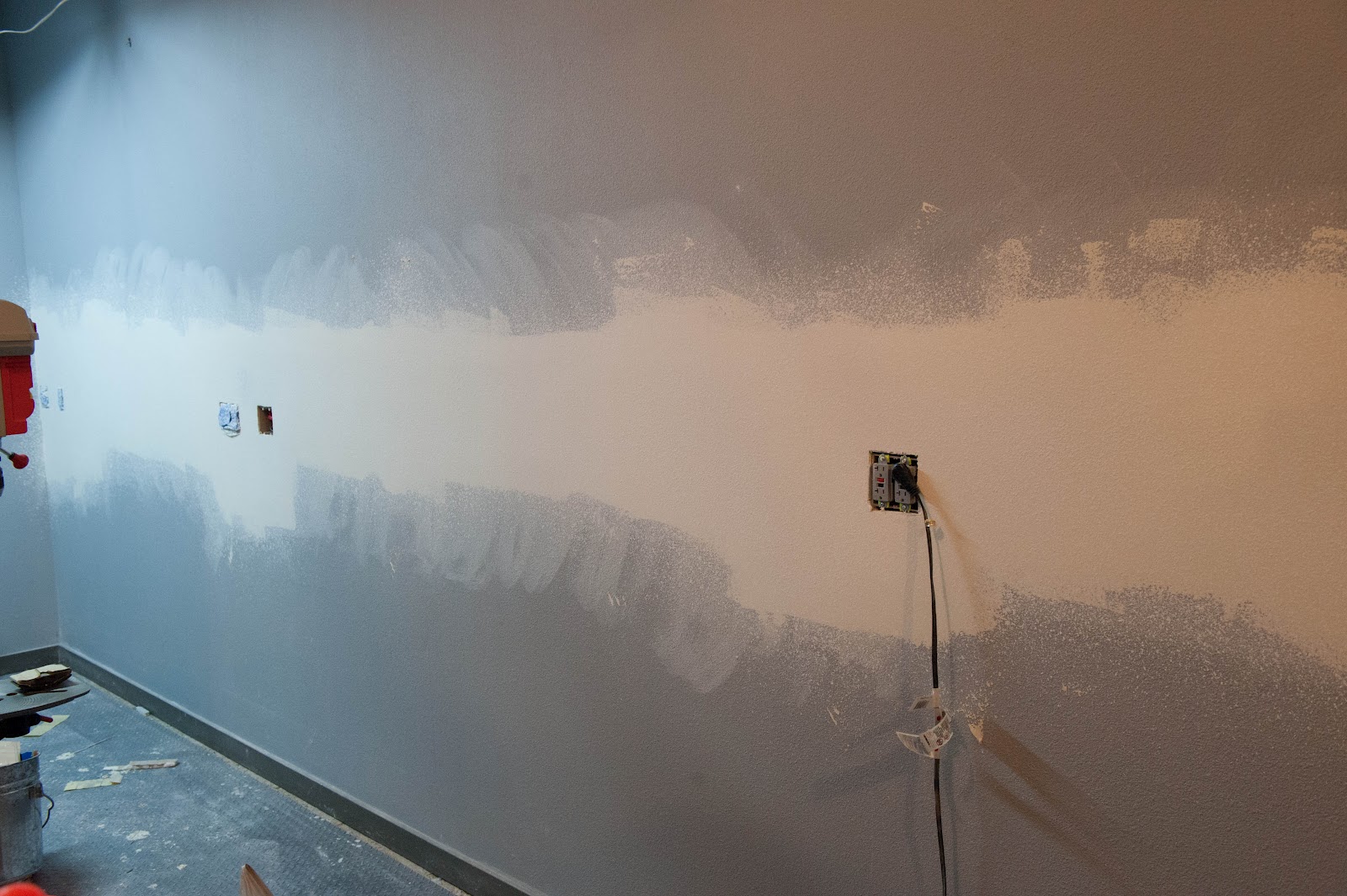
Installing the new 30a wiring & Drywall back on

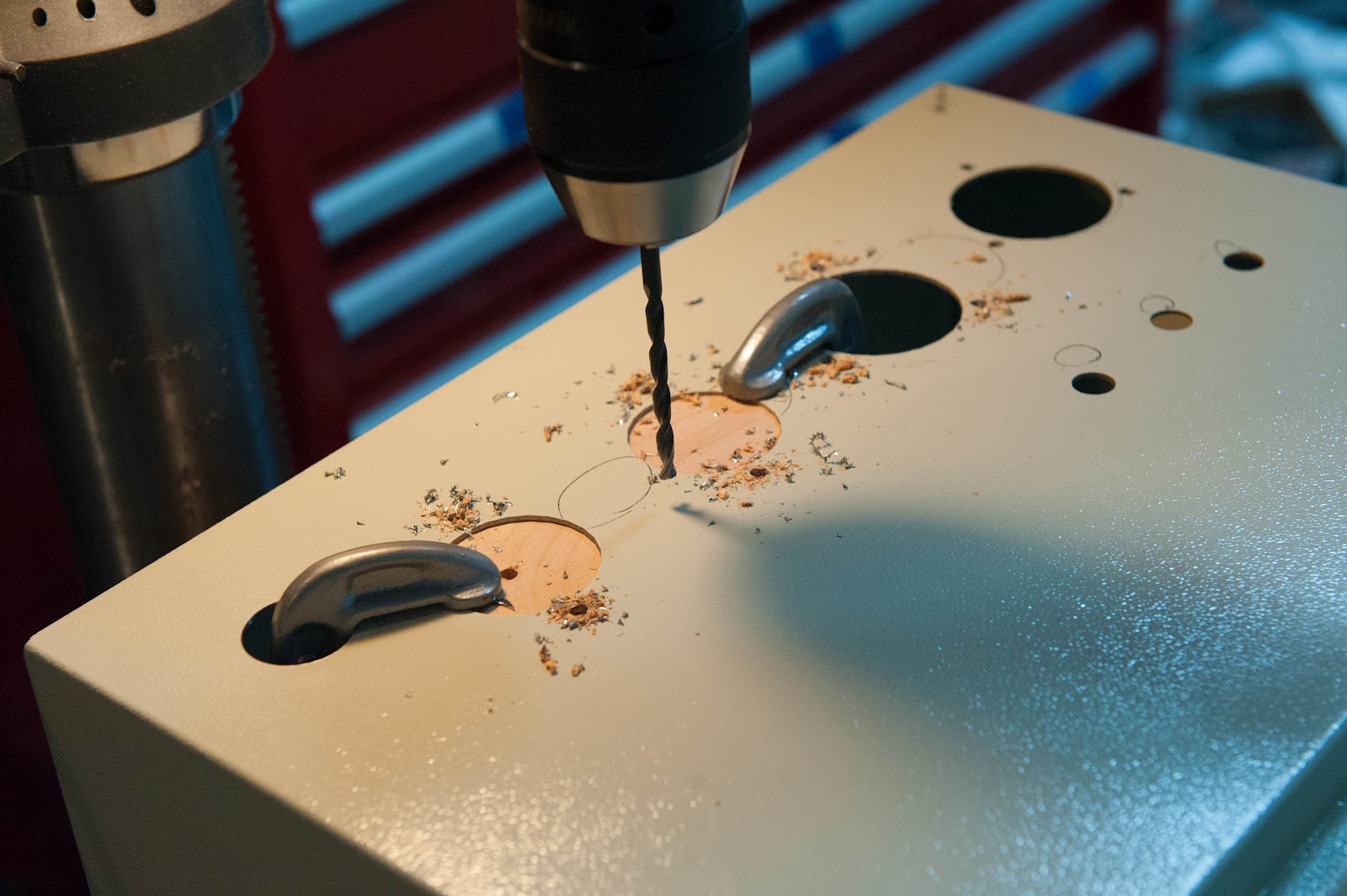
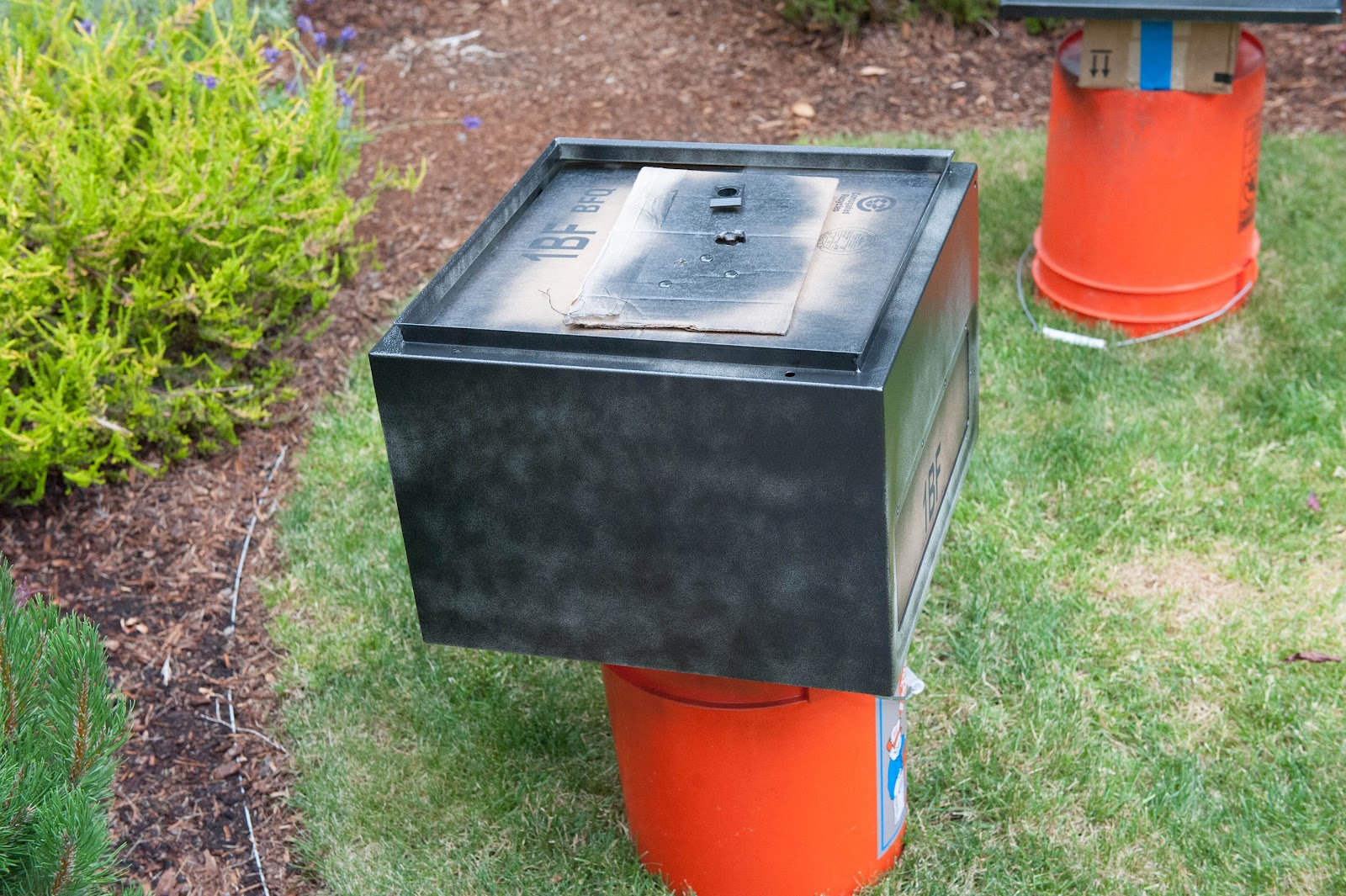
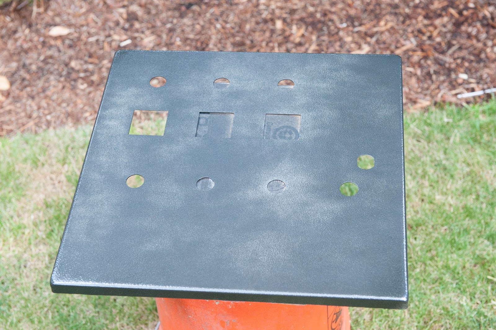
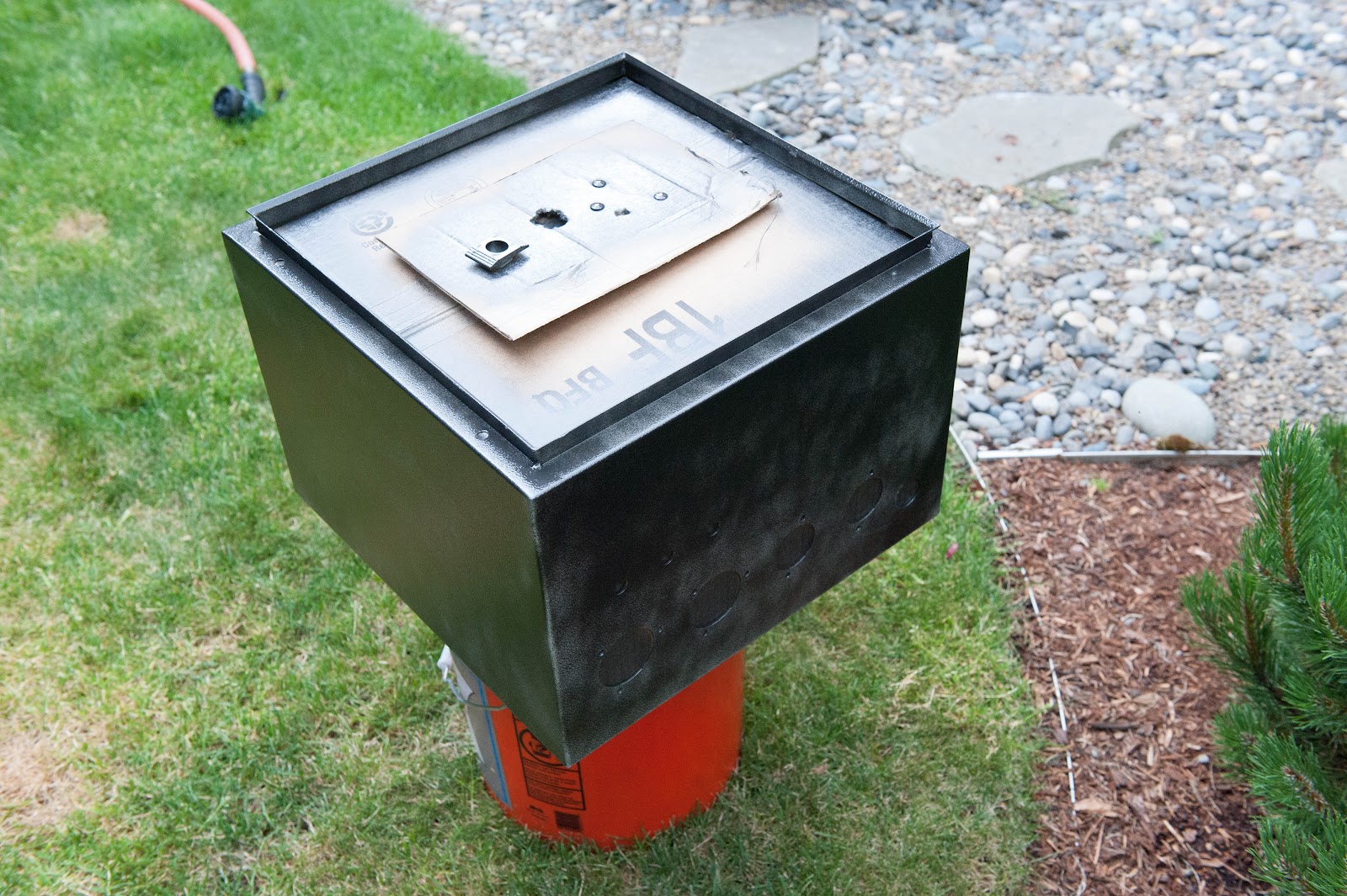
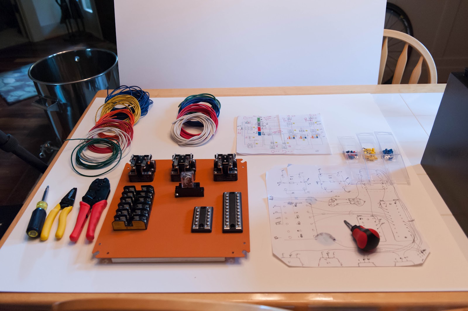
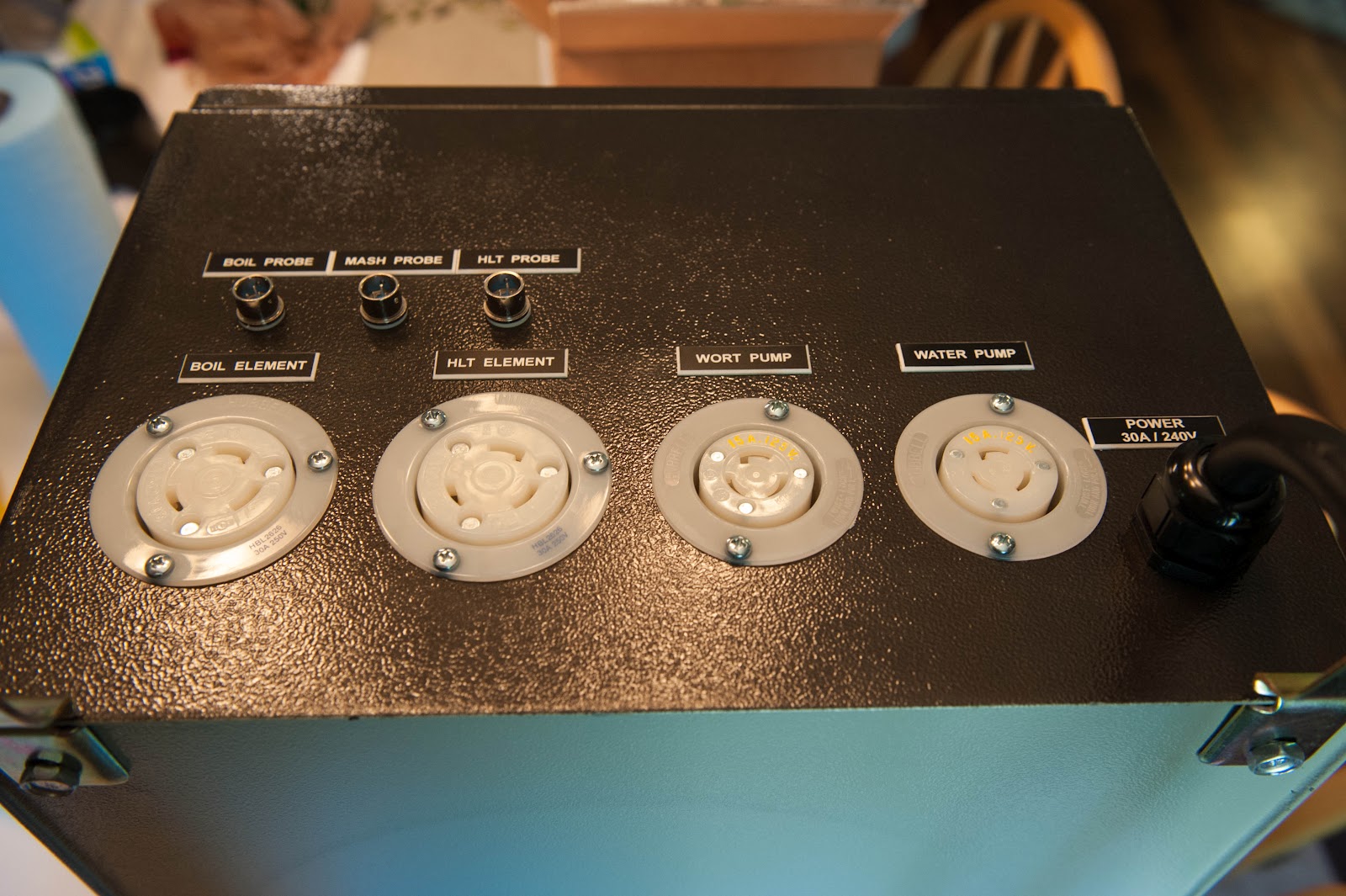
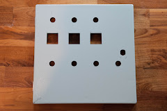
Waterjet Cut Panel
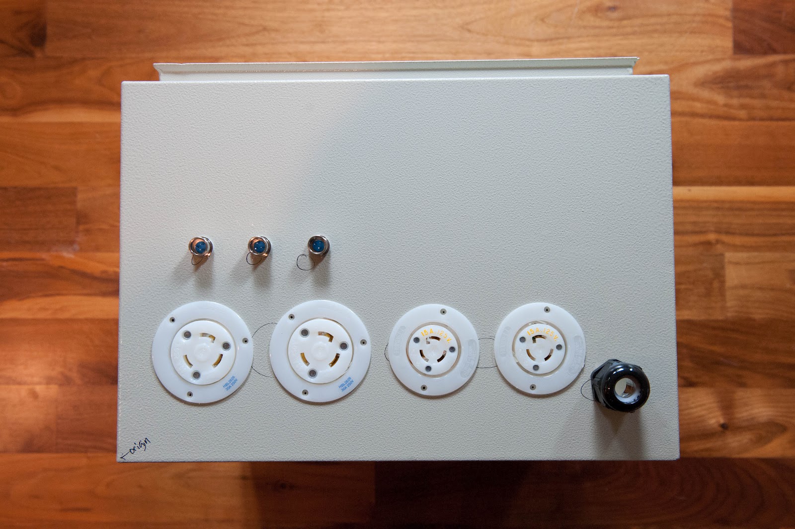
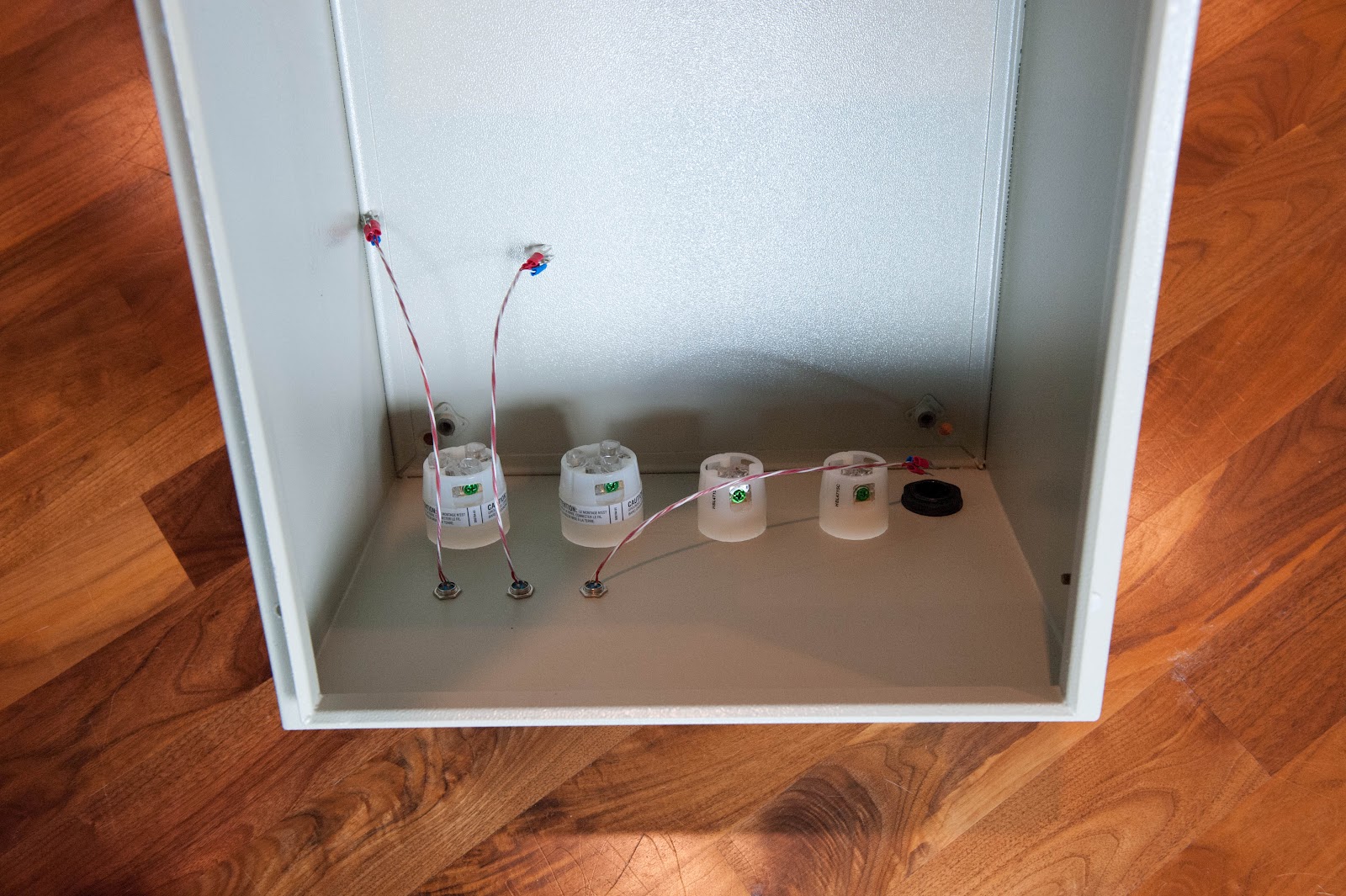
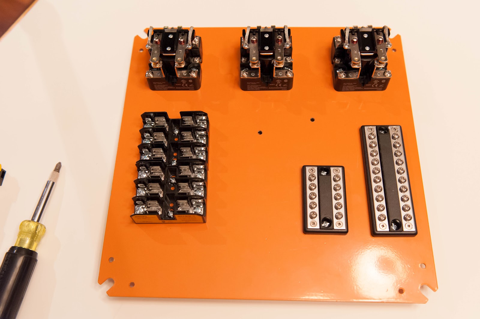
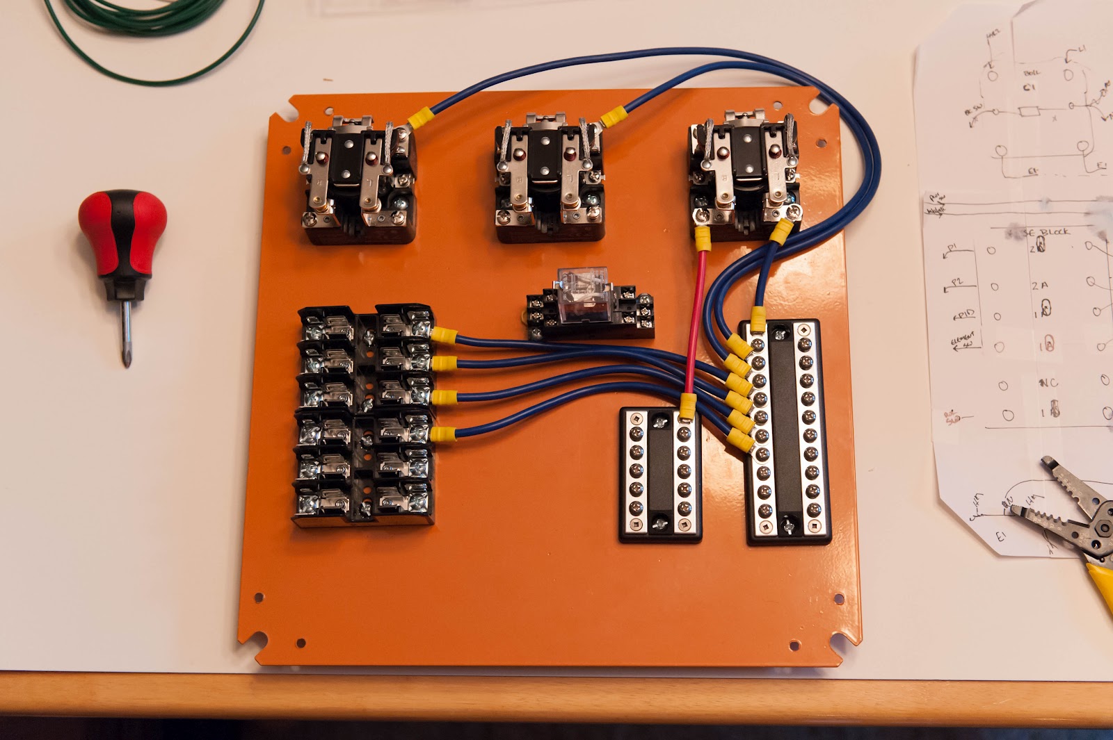
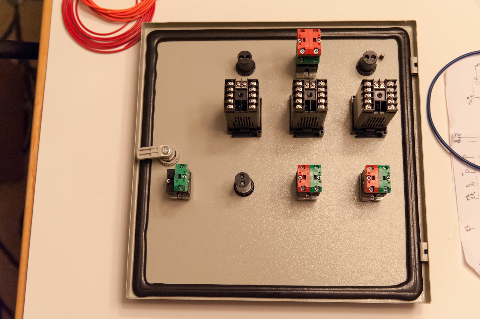
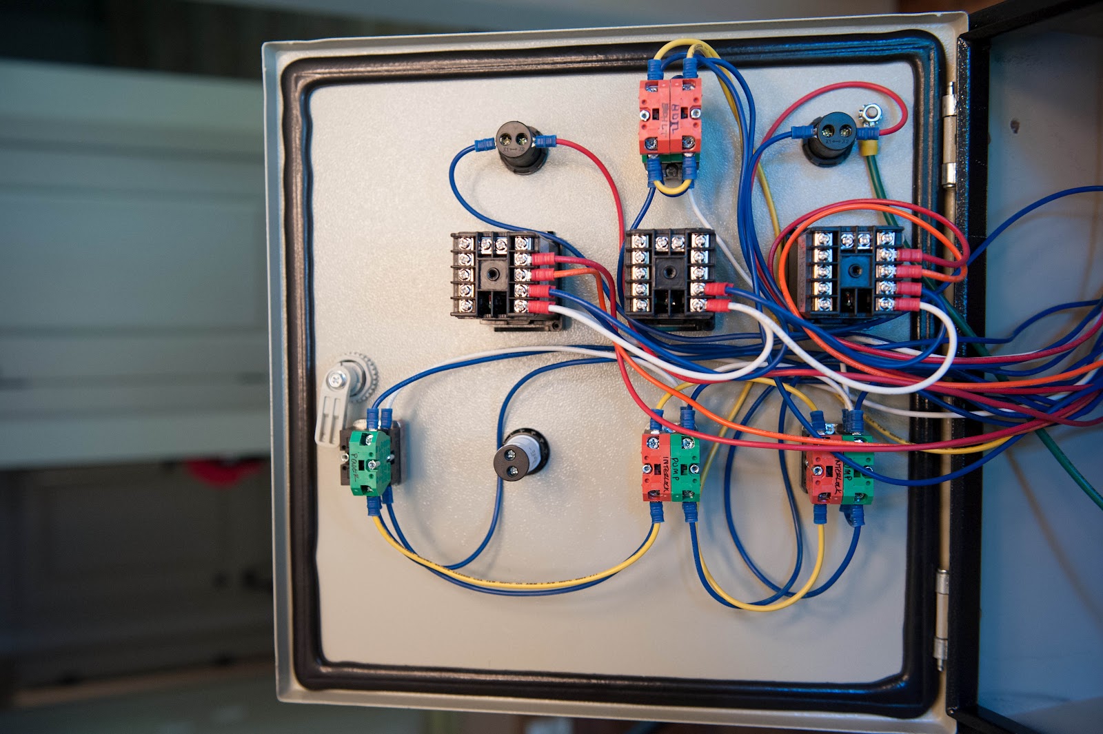
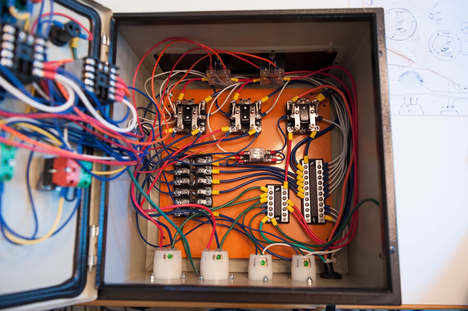
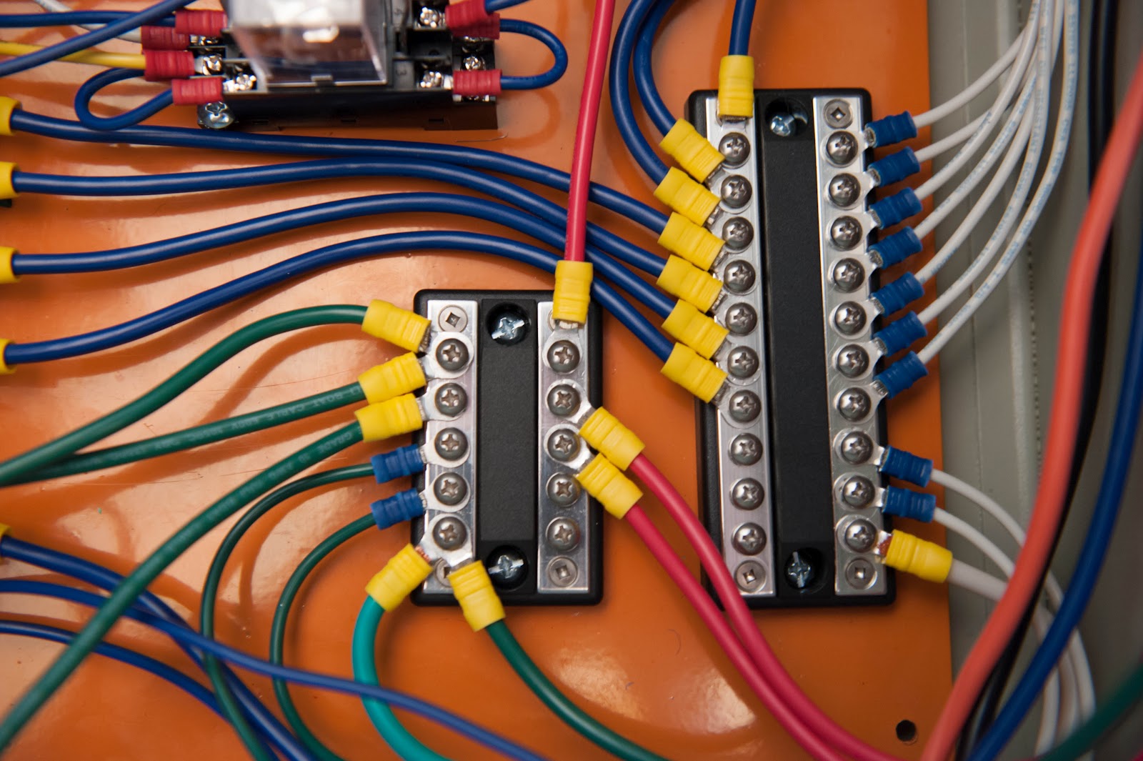
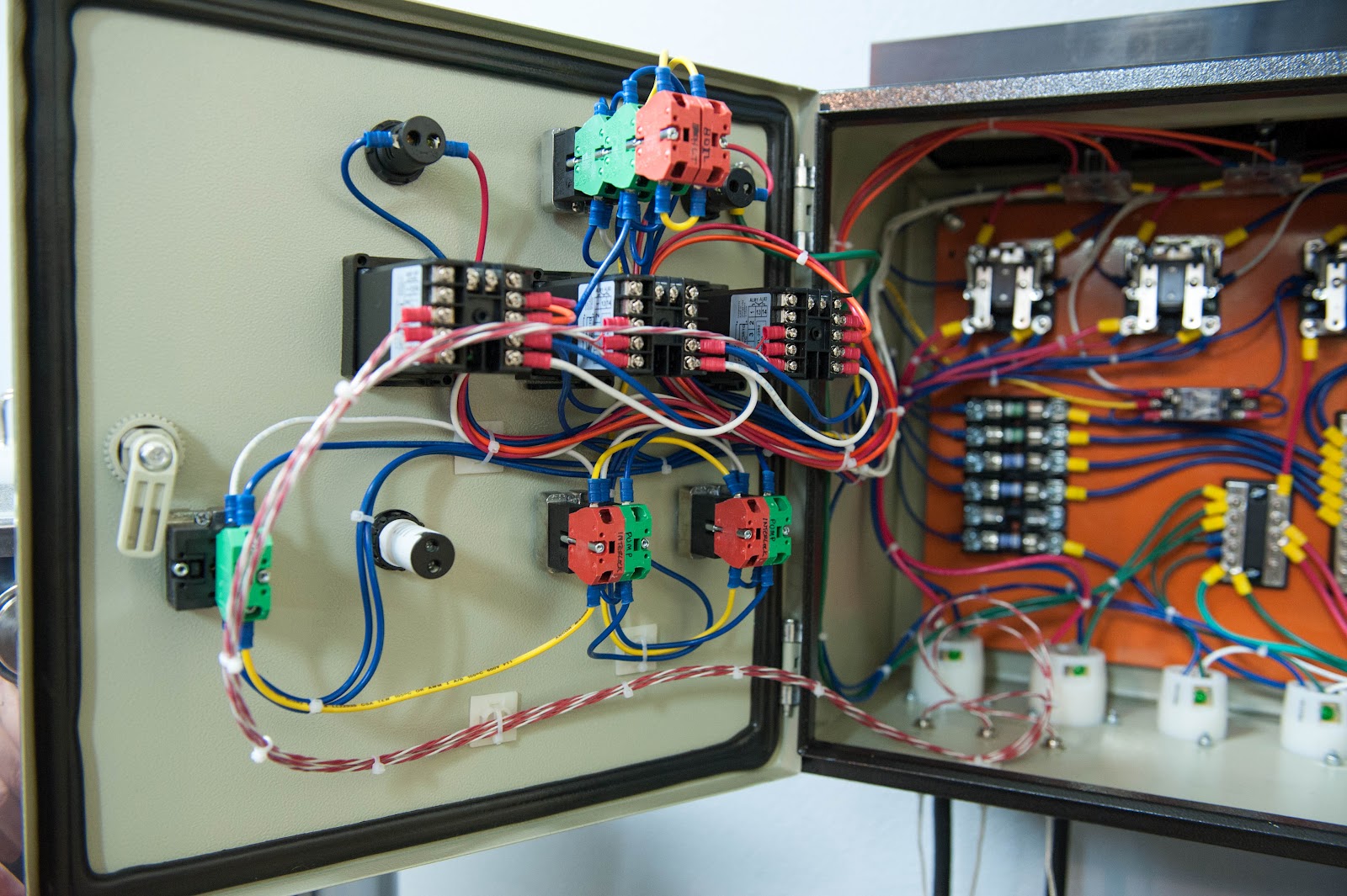
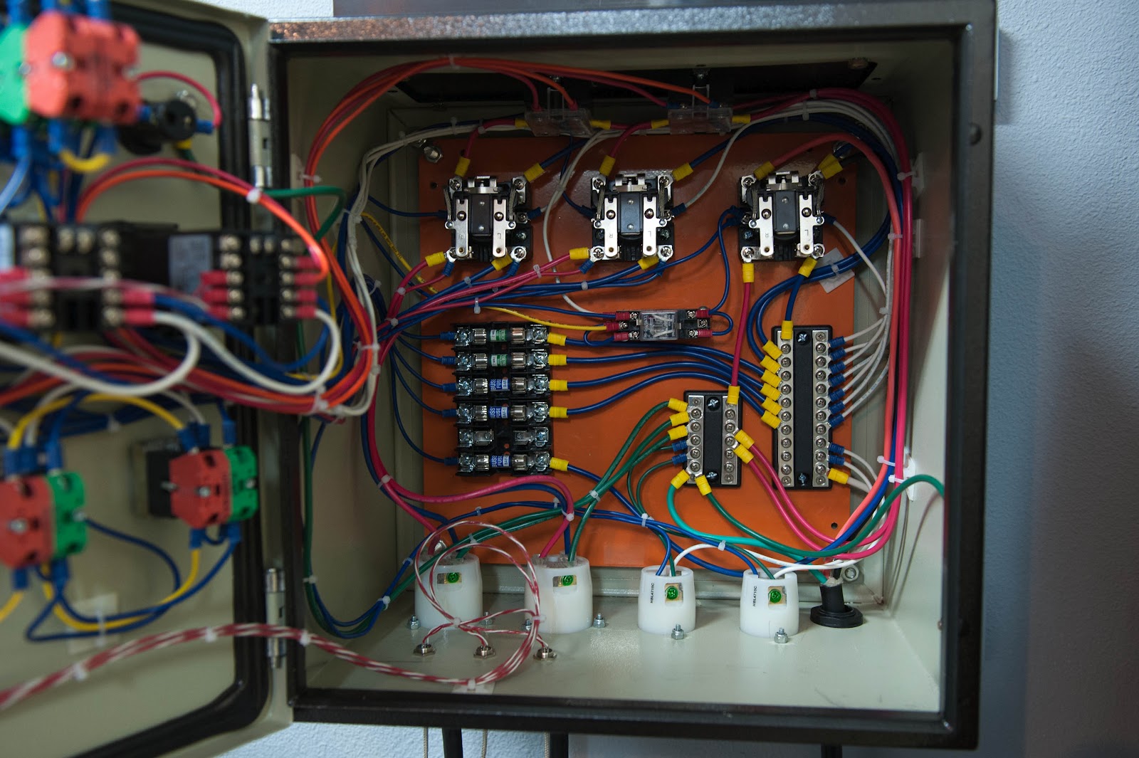
Wiring the Panel

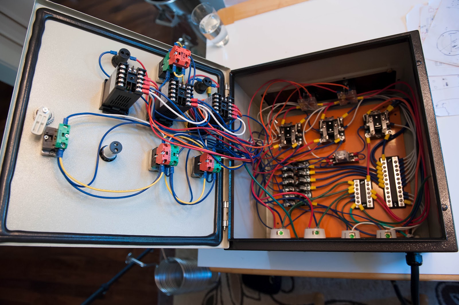
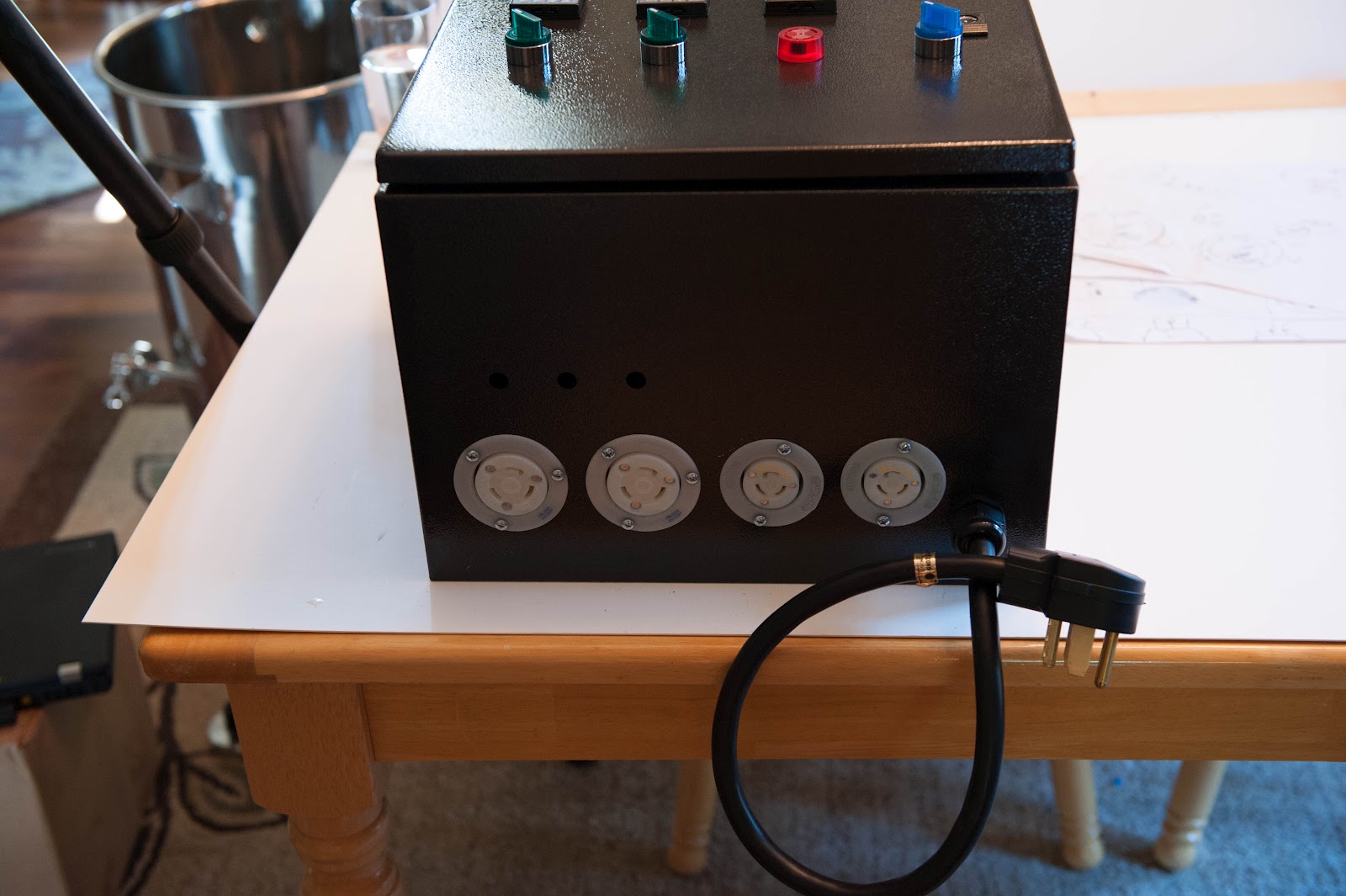
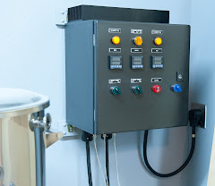
Panel is tested and installed
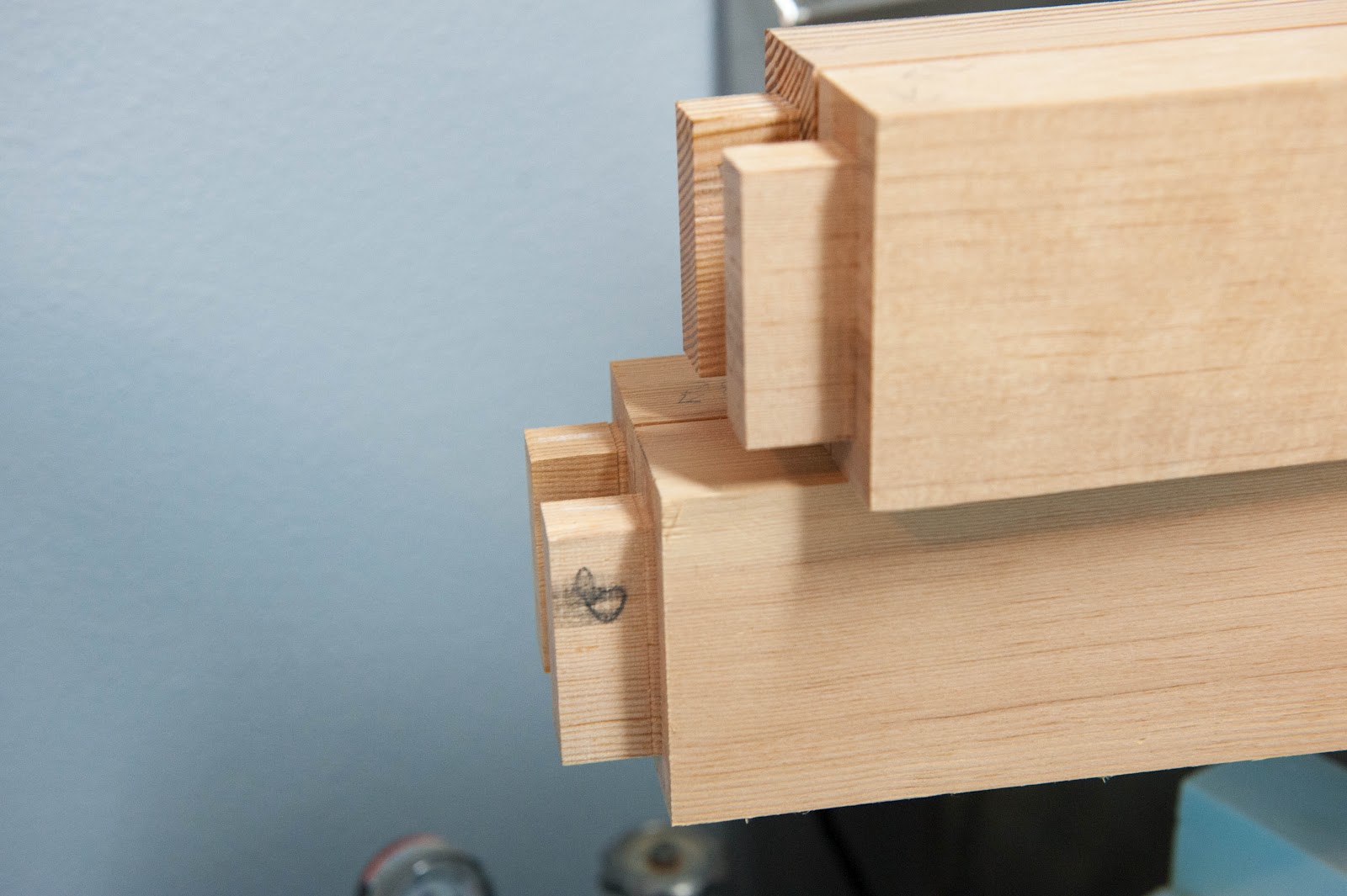
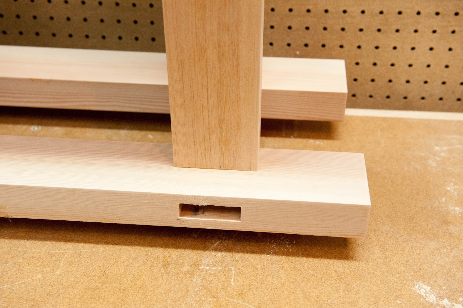
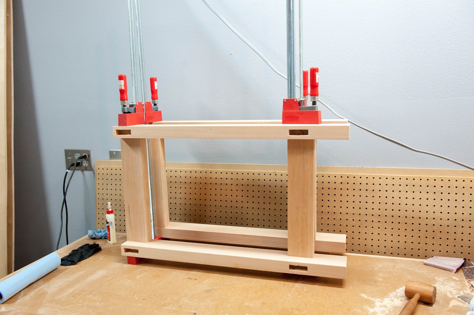
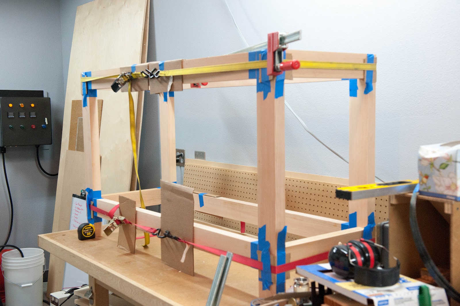
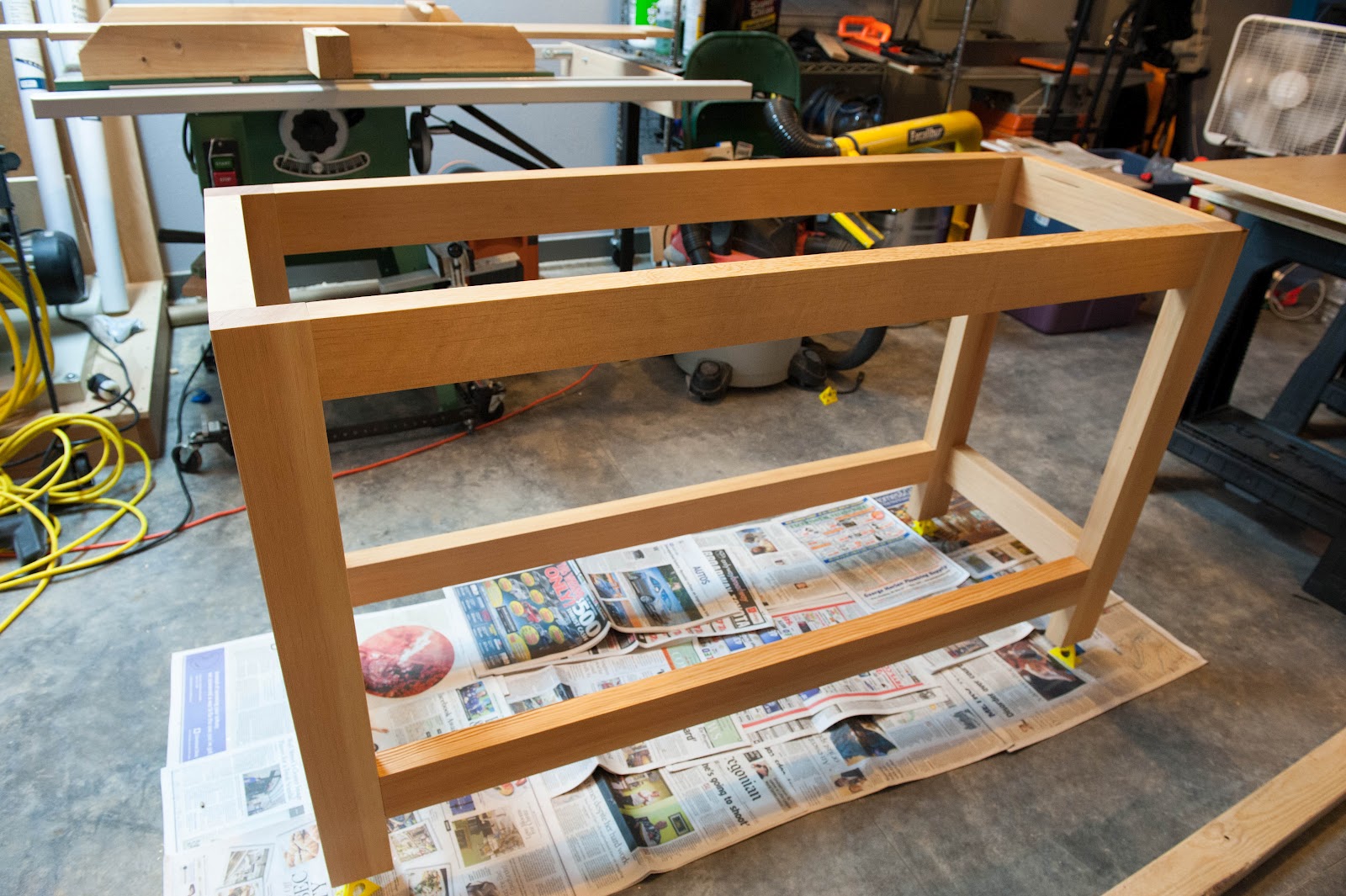
Building a Bench

- Linked up various posts throughout the thread on the build
- Posted the final schematic below
- Posted the Bill of Materials here and in post #60
- Added my "What I would do differently" in post #61
It's time to start the build thread. Inspired by Kal's setup and a bunch of threads here, I've embarked on my own electric brewery upgrade. I've been successfully brewing all grain with an orange cooler and a 10g blichmann over propane for a number of years. The beer has been great. However, the consistency has been sketchy to recreate batches -- mostly mash temps and boil-off rate. Moving to HERMS and electric should address the consistency -- and it's just fun to build stuff. I'm also moving up to 10 gallon capacity.
The kettles are finally here, a 20 gallon setup from Stout Tanks with additional fittings for electric elements. I think I have all the control panel parts and my electric permit is in hand to run the new circuits in the garage.
The control panel is a 'light' version of Kal's. I dropped the voltage/amperage meters, the timer and the alarm switches -- but kept all 3 PIDs. I also combined the switches and pilot lights where possible. I have some future plans to switch from the Auber PIDs to Arduino control -- slowly.
The TODO list isn't too long, but I'll keep a running log of projects here. This includes adding the new circuits (30a and others), the control panel build and the brew space. I've convinced myself I can build a concrete bench/countertop for the kettles; should be fun.
Before...
After...
Final Schematic
Available as a PDF or Visio
Bill of Materials
https://www.dropbox.com/s/w1e8w9kr0okyuwp/Parts.xlsx
Commentary in post #60
Build Updates
Installing the new 30a wiring & Drywall back on
Waterjet Cut Panel
Wiring the Panel
Panel is tested and installed
Building a Bench
")