DIY electronic fermentation chamber heater

Homebrew Talk - Beer, Wine, Mead, & Cider Brewing Discussion Forum

Help Support Homebrew Talk - Beer, Wine, Mead, & Cider Brewing Discussion Forum:

This site may earn a commission from merchant affiliate links, including eBay, Amazon, and others.

Nebuch

Member
Joined
Dec 16, 2008
Messages
22
Reaction score
0
My house temperature fluctuates a lot during the day. My basement goes from 68 F to 56 F throughout the day. For the Ales i plan to brew during these cold months, I plan to make a temperature controlled chamber. At the moment I'm only focusing on heating the chamber. When spring comes I will setup up a cooling element too.

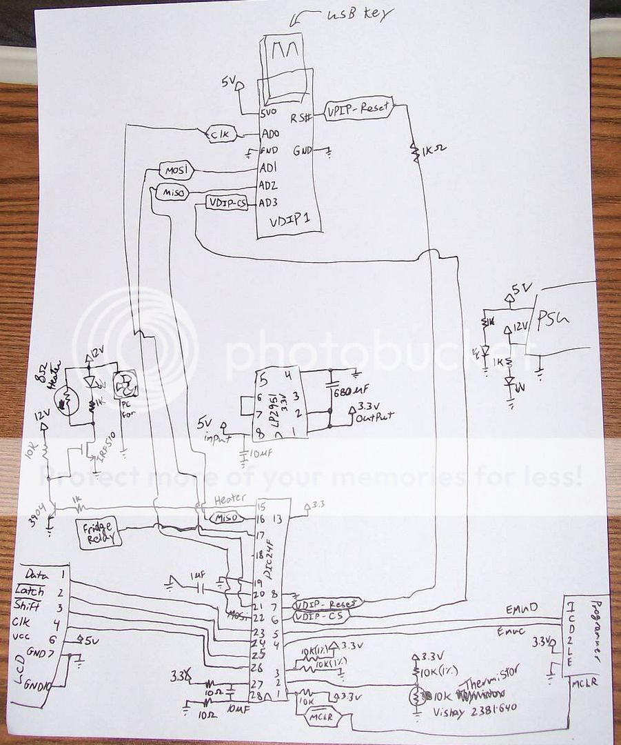
Coincidentally, I had all the pieces i needed lying around. The thermistor I used was a Vishay 2381 640 which is 10K ohm at 25 deg C. I used the PIC24FJ64GA002 micro controller. For logging temperatures, I used a VDIP1 module to write the temperatures and various other parameters to a USB thumb drive. I used a couple power resistors to generate around 18 watts of heat into the chamber. It's not a lot of heat, but I'm limited by the power supply I'm using. I also used an LCD to display the temperature.

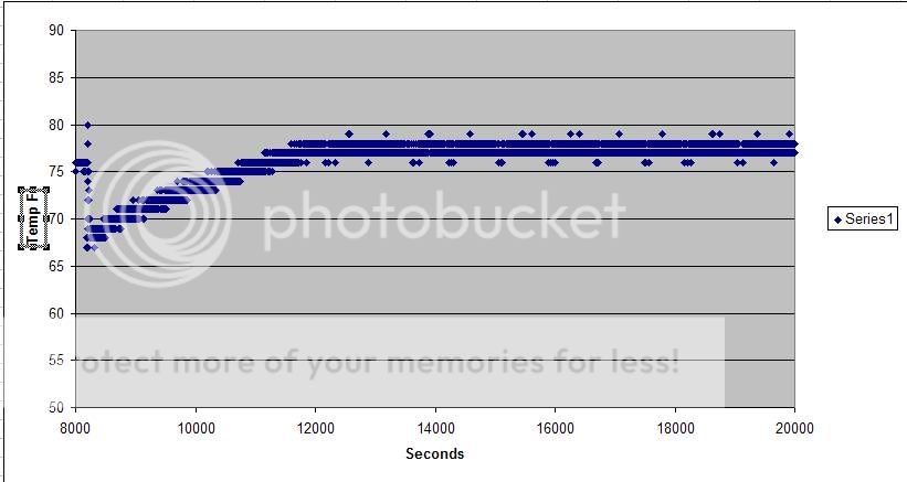
I stuck the heating component into a mini fridge, which is unfortunately too short for a carboy, but a plastic bucket will fit. The temperature range i picked was 76 - 79 deg F just for testing. The ambient temp was about 68.

Here's the temps inside the mini fridge (mini fridge was unplugged):

pic1.jpg


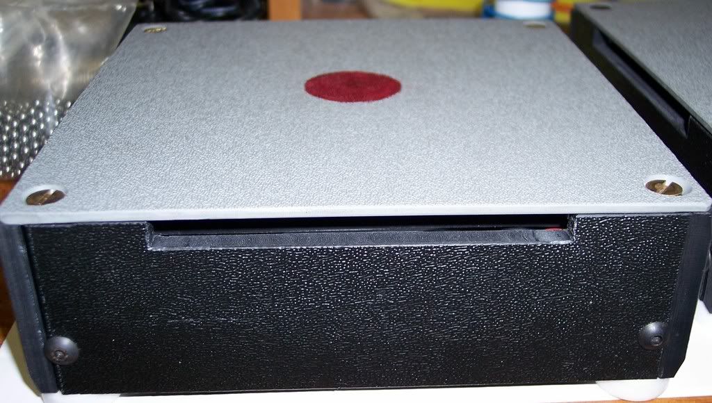
Here's the circuit in operation:
pic2.jpg


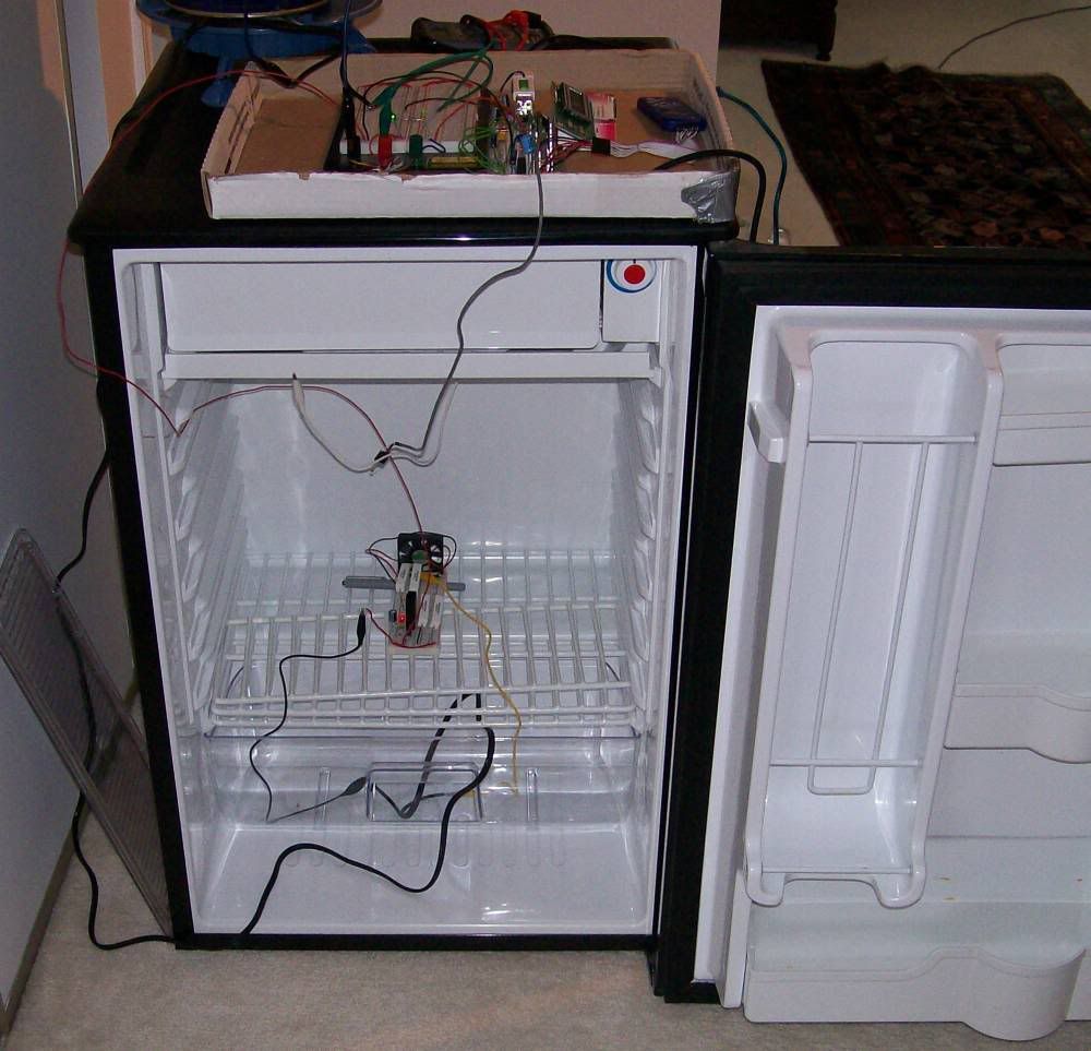
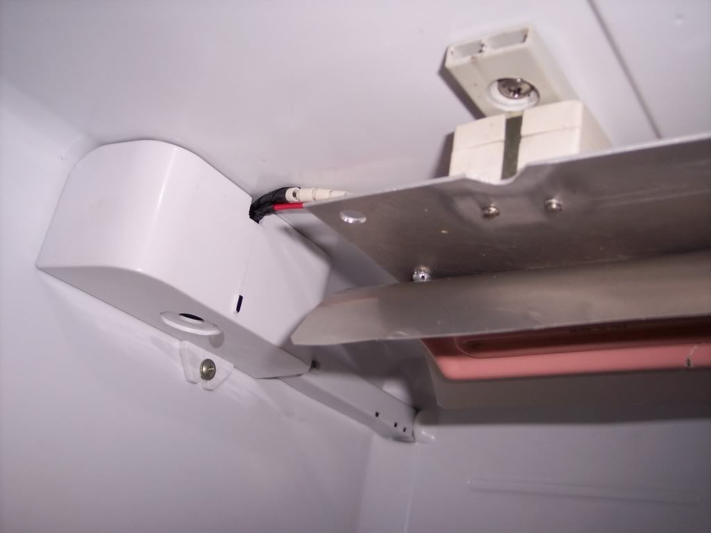
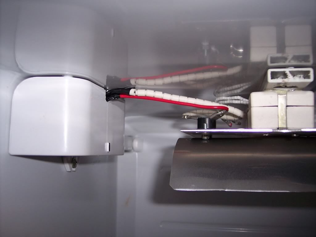
You can see the white ceramic power resistors inside. I used 4 of them so they don't get hot enough to be a fire hazard. Ideally, I would use a 100+ watt resistor strapped to a huge heat sink but i don't have one on hand. There's a small computer fan in there too to circulate the air and there's a FET switch transistor with a black heat sink. The grey wire coming over the top is the thermistor which is used to calculate the temperature.

Here the display shows 68 F because the door is open:
pic3.jpg


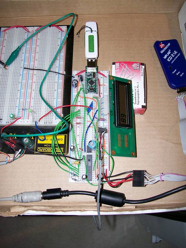
I'm using a 12v 2amp, 5v 2amp laptop power supply. The circuitry runs off 5v which is stepped to 3.3v with a regulator (LP2951). The 12v is solely for the heating resistors which is controlled with a transistor. It wouldn't be hard to replace the power resistors with a relay to switch on something more powerful.

Now i need to make a larger chamber to fit a glass carboy.

If anyone is interesting, I can post the firmware and schematic.
 
You happened to have all those parts laying around? Do you also have a hunchbacked assistant?? *no offense if you or any member of your immediate family is, indeed, a hunchback*
 
I was PMed about the schematic so here it is. Nothing fancy but it's what's on the breadboard. I'll include some notes on using this too.

beerheaterschema.jpg


I used a pretty proprietary LCD (optrex im50240) with shift registers. So you might have to skip the LCD or wire it for a different unit.

Also the VDIP1 has gone up in price by a lot, so the project isn't totally economical.

The heater control is opposite of convention, so high signal turns the heater OFF. Low turns the heater ON. Stick an inverter in there just in case the PIC fails, so the heater turns off.

I don't recommend building this unless the user accepts all responsibility for any damages it may cause, like a house fire. The power resistor can get very hot and resistors that are too small will burn up and cause a fire. The user should also have some electronics experience to debug the circuit.

Edit: Code is too long to post in here :(
 
I'm going to reply to a PM here since it's related to the project and might be useful for anyone else looking into similar projects. This will outline my method for reading thermistors.

The method i used to sense the temperature is with a thermistor. The one I'm using is NTC (negative temperature coefficient) which means the resistance goes down as temperature goes up. It's essentially a resistor that changes resistance with temperature.

The temperature of the thermistor is calculated from a formula from the data sheet:

Temperature = 1/(A + B*log(R/Rf) + C*(log(R/Rf)^2) + D*(log(R/Rf)^3))
A = 3.354016E-3
B = 2.56985E-4
C = 2.620131E-6
D = 6.383091E-8
Rf = 10000
R = the resistance of the thermistor

This sounds complicated, but the data sheet also lists a table so you don't need the formula. The formula is too complex to implement on a microcontroller; as an alternative I used a look up table (in C):

long resistance[214] = {86173,
83487,
80894,
78391,
75973,
...

int degf[214] = {0,
1,
2,
3,
4,
...

float degc[214] = {-17.8,
-17.2,
-16.7,
-16.1,
-15.6,
...

The look up table works by comparing the thermistor resistance to the values in the resistance array. The array index of the nearest value is recorded. That index is then used to get the degf and degc. So 75973 ohms means 4 degrees Fahrenheit.

If you do use the formula, you might note that my numbers are slightly skewed. This is just because of the way i check the resistances.

The PIC, as with other micro controllers, have analog-to-digital pins. These record the voltage at the pin. The PIC's 10-bit AtoD will read 1023 @ 3.3v, and 0 @ 0v. To convert the thermistor resistance to a voltage for the AtoD to read i stick another resistor in series with it. Since the thermistor is 10K ohm at 25 degC, I used a 10K ohm resistor in series with it. This will make the pin voltage at 25 degC be half of 3.3v, 1.65v. Now when the temperature goes up, resistance goes down, voltage goes down.

So, now we can read the voltage and (with a bit of math) the resistance. If you look at the value in the micro controller you might see that the number is slightly skewed and you'll have to add, subtract to compensate. In my case I had 1.65 volts read as 516 (out of 1023) instead of 512. However, a fancier way to compensate is to setup a bridge. I put two more resistors in series which were both 10K ohms and 1% tolerance (very precise). I then read the voltage between these resistors and low-and-behold it gave me 516.
The voltage read between the two 10K ohm resistors is a reference.

I did a bit of math and came up with a formula that converts the reference and thermistor voltage into the resistance (in C):

thermistor = (double)TEMP / (double)(REF+REF-TEMP);
thermistor = thermistor * BRIDGE_RESISTOR;

Where TEMP is the AtoD reading of the thermistor.
REF is the AtoD reading of the reference.
BRIDGE_RESISTOR is the 3 resistors' value in the bridge, 10000 in this case.

The 'thermistor' variable has the resistance to apply to the look up table.

So far I used 2 AtoD pins on the micro controller, but the PIC24 I used has about 5 usable pins for AtoD. I can keep adding resistor+thermistor pairs (~$0.93 each) for more temperature sensors while keeping only one reference for them all.

To use the VDIP1 to write to USB is a bit more complicated and i'll cover it in a post following this one.
 
I'm going to reply to a PM here since it's related to the project and might be useful for anyone else looking into similar projects. This will outline my method for reading thermistors.

Nebuch - Thanks for posting this information, it's going to be a great starting point, and I suspect it will consume many upcoming nights and weekends. :ban:

Nice job!!
 
Wow, and I just bought a $5 space heater with a thermostat on it. Your heater is WAY out of my league!
 
Nebuch;
Check out this company below on their strip heaters, they range from 20 watts to 1,000 watts 120 volt to lower than 1,000 watts and higher at 240 volts.
With what you have in equipment add a computer fan to come on with the heater plus add a snap thermo over temp around 120 degrees to a chamber or sheetmetal duct for the element and fan to mount in. The element can run without any fan without over heating but you will not get the heat were you need it without a fan. Check out pages 5, 6 and 7 for round disc heaters if they can help you with their specs and wattages of these strip heaters.

http://www.tempco.com/Catalog/Section 8-pdf/Mica Strip.pdf

Hope this helps. Cheers. Carl........
 
Nebuch very nice project.

I converted a cube Heier fridge into a incubator.
The heater is a Sylvania 500 W, 230 V IR SYLVATHERM element.
I use the heater as a 125 W unit on 120 V.
Installed a over temperature snap action switch on top of the mounting plate.
For my application the air circulation is done by my stir plate fans.
The stir plates are equipped with cutouts.

Heater-wiring.jpg


Heater_wiring.jpg


IncubatorStirPlate.jpg

Cheers,
ClaudiusB
 
Thanks for the ideas. I'm now rolling around the idea of using a peltier for cooling.
 
I really enjoy the use of the breadboard and the data logging is always a plus. I can only hope that you will etch your own circuit board for your final setup. (joking)
 
I have a friend who said he could etch the boards for me. I really should ditch the breadboard, I'm sure it's not too happy with the amps I'm pushing through it. The peltier I found needs 8 amps so the breadboard is definitely out.
 
Nebuch, I have been thinking about building an almost identical apparatus from a PIC 18... Would you be willing to share what you have so far?
 
OK,

My idea isn't quite so geeky, but mainly because of time constraints (I have degrees in electrical engineering, computer engineering, and electronics and computer control systems).

I was thinking of a simple thermistor based comparator circuit controlling a relay which turns on a 40W light bulb! Maybe 75W for the winter, depending upon the size of the chamber. Add in about 1 deg F of hysterisis and done!

I personally think air circulation is more important than the amount of actual heat, especially for small enclosures like a fridge. Try adding a PC cooling fan to your setup and see if the temp control stays tighter. I'm guessing it will.

Nice work.
 
I'm currently in the middle of something very similar. I'm using some easier to use parts (LM34DZ and Arduino) and is going to handle 1 - 6 temperatures and just switch some AC power (120v @10A) to turn on/off what ever hot/cold source you want (I was considering using a couple heating pads for my heat source, but i still need to think about it. I plan on posting parts list and some build shots for people interested. I just got done building the box tonight and the electronics are on the way.

Nice work!
 
Just stopped by Wal-mart yesterday to pick up a tire plug kit, and looked through their space heaters. Picked up a digitally controlled unit with LED display for $21 on clearance!

I know this isn't as much fun as writing PIC code, but it's done, it's cheaper and it includes a fan; I'm happy. Now since my fermenting closet in the basement is not finsihed yet, I have to decide whether to finish that up, or make a temporary shed/shelter. Maybe I'll set up my hunting blind down there. At any rate, whatever I setup I'll monitor the actual temp with my wireless thermometer and see how steady she stays.

This is a good time of year for finding these heaters on clearance, so just a heads up for anyone interested.
 
Sorry for not replying for so long. I was away for a month. I got a decent size peltier, strapped some heatsinks to it and a centrifugal fan, and let it run. It gathers a fair amount of frost in little time. I froze a temperature sensor to it and it was reporting around 10F or -12C. I found an old cabinet in the basement with a hole in the top too. I just hope it can cool a few cu. ft.
 
hot stuff. did you program in assembly or use a compiler? I'd be interested in your code.

I've never seen the FJ pic processors - only used the F and C... my chip burner probably wouldn't work on that.
 
It's in C. I used the MPLAB IDE, and C30 compiler. The ports and control registers will need to be redone for a different chip.

Do you have Windows Messenger?
 
Nebuch, I'd love your code if you're willing to share... I'll be using it as a template for my project on a Pic18F2550. If you are willing to share, please email to neocount @t gmail

Thanks!
 
just checked this thread. I don't use windows messenger, is the code too lengthy for a pm?
 
I'm also interested in the code, understanding that changes will be required to adapt it to my application. If you're still willing to share it could you point me to a place where I may download it, or e-mail it to [email protected]?

Thanks,
Joe.
 
subbed...this looks like an interesting project now that I'm getting into arduino and RasPi programming.
 
Back
Top