Contactor Wiring Help

Homebrew Talk - Beer, Wine, Mead, & Cider Brewing Discussion Forum

Help Support Homebrew Talk - Beer, Wine, Mead, & Cider Brewing Discussion Forum:

This site may earn a commission from merchant affiliate links, including eBay, Amazon, and others.

TriangleIL

Well-Known Member
Joined
May 6, 2010
Messages
222
Reaction score
3
Location
Chicago
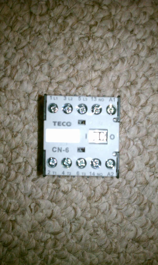
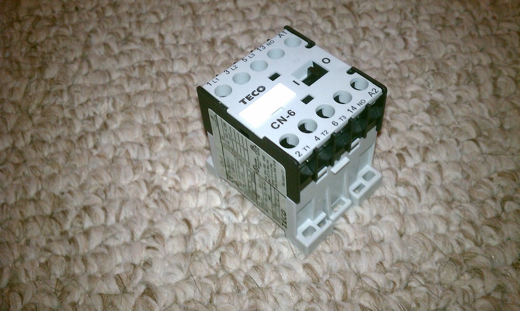
I purchased some contactors awhile back, and have no idea how to wire them up. Can anyone provide some assistance? These will be used to switch on/off my pumps. Thanks!

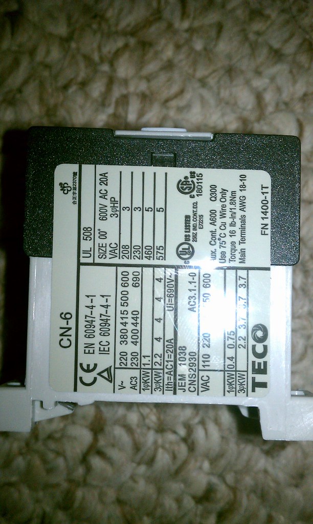
They were purchased from AutomationDirect, but it looks like they don't carry the CN-6 anymore. FactoryMation link

6957409255_354904f270_b.jpg


6811298472_ee9d46f172_b.jpg


6811299098_e0fc502ff1_b.jpg
 
Thanks for the link. I've found similiar manuals, but nothing on wiring, or at least - that I can tell. I'm also concerned, from the specs it looks like this only supports 3 phase? Maybe these contactors won't work? Crap.
 
I'd be willing to bet it'll work just fine.

Take a multi-meter and close the contacts then check each contact for continuity.

Looks like L1 and T1 go together, L2 and T2 go together, and L3 and T3 go together.

Looks like there's a manual switch too. 1=On, 0=Off. Nice feature.

I just don't know where the coil connections are. Probably A1 and A2 if not anywhere else.

Good Luck!
 
Yeah, what stlbeer said. Generally, L terminals are the line side input and T terminals are the controlled load side. I would guess A1 & A2 are the coil terms and 13 & 14 is a set of pilot contacts with a much lower current rating than the main L1-3 contacts. Typically, these contacts for additional control / sequencing or indicator functions. The manual I/O tab is a handy visual indicator if the armature is pulled in magnetically and provides a means of manually operating it for test purposes.
 
Re: 3 phase: You don't need to use all 3 main contacts. Just as many as you need.
 
Great, thanks everyone. This was really helpful and I'll give it a try and report back!
 
But those contactors are only rated at 20 amp (or am I reading that wrong) - what size element do you plan to use?
 
stlbeer and junkster hit it right on the nose for the wiring A1 A2 are coil and 13,14 are a NO auxiliary contact set. You will be just fine using this for your pumps and can run up to a 4500 watt element if you ever decide you want to.
 
So I wired this all up, and the control voltage (24VAC) isn't causing the contactor to 'kick over'. The manual switch works just fine. I tested the voltage over the A1/A2 connection and I'm getting 24VAC. I'm fairly certain they are rated at 24VAC to kick, any ideas?
 
where are you getting 24VAC from? It looks to me like 110VAC from the back of the hardware.

However - please confirm this with one of the electrical guys as I consider myself a novice with this stuff.
 
where are you getting 24VAC from? It looks to me like 110VAC from the back of the hardware.

However - please confirm this with one of the electrical guys as I consider myself a novice with this stuff.

It looks like that is the main contact rating info.

The coil voltage should be printed on the coil itself. Sometimes it is visible on the side of the contactor. If not, you should be able to take it apart and read it off the coil.
 
It looks like that is the main contact rating info.

The coil voltage should be printed on the coil itself. Sometimes it is visible on the side of the contactor. If not, you should be able to take it apart and read it off the coil.

Exactly why I appreciate electrical savvy folks such as yourself. Thanks for correcting.
 
On the westinghouse/teco contactors they will have a suffix number after the model#. So yours should read CN-6-B6 for a 24v coil or CN-6-F6 if it is a 120v coil.
 
On the westinghouse/teco contactors they will have a suffix number after the model#. So yours should read CN-6-B6 for a 24v coil or CN-6-F6 if it is a 120v coil.

Paul,

That's sort of the problem, I don't see an indication on the label like you specify.

See picture 3 in the first post.

Paul
 
Paul,

That's sort of the problem, I don't see an indication on the label like you specify.

See picture 3 in the first post.

Paul
I dont see one either, was hoping it was marked where the glare of the camera flash hit or on the back side.
 
You guys all rock. Thanks for the help! I found a marking that said 230V/60Hz near the coil. I'm not sure how my moronic self missed that before. I rewired the panel, used my 220V hot legs, and boom she worked!

The three phases ended up working out beautifully so I could pass the 24VAC through another one of the lines (L2/T2) and back up to the 24VAC indicator to show the pumps are on/off. I just passed the 220V through my switch instead of 24V, and ran a new wire from the second output on the contactor to my illuminated indicators. My panel is alive!

Thanks again for all the help!! Love this place!
 
Back
Top