Why did my circit breaker pop?

Homebrew Talk - Beer, Wine, Mead, & Cider Brewing Discussion Forum

Help Support Homebrew Talk - Beer, Wine, Mead, & Cider Brewing Discussion Forum:

This site may earn a commission from merchant affiliate links, including eBay, Amazon, and others.

Photopilot

Well-Known Member
Joined
Jul 9, 2007
Messages
1,196
Reaction score
123
Location
Jackson
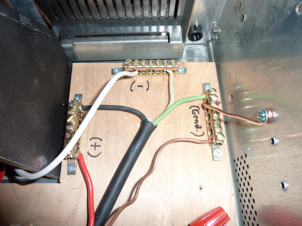
Here is the photo of my control panel. I just finished wiring it on Sunday in preparation of my first 10 gallon batch. I had been prepping water and the rest of my brewing equipment all morning, then when I plugged the panel in the GFCI popped immediately as did the CB in the panel and the inline fuse. I tried a number of times and each time the power went towards the element the CBs popped. I am wondering if it is anything to do with the wiring or is it a short in the element wiring. I changed plans and did a 10gallon all grain stove top brew. It made for a long day.

I am hoping for suggestions as to why the CB was popping so I can begin testing tonight.

I have a 3 wire feeding the 240/120 of a spa panel CB panel and the ground comes from a 120V GFCI from a different circuit that powers the PID only, as well as ground for the case and heating element circuit.

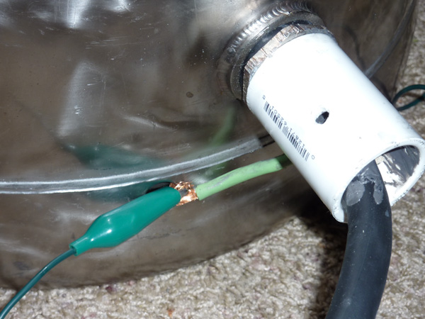
My heating element is potted in a PVC coupler. I attempted to put a ground wire screw into the base of the keg. I went through 4 batteries and broke a bit. I took the ground and used an alligator clip to ground the keg. I tested the ground on the plug attached to the element cord and there was continuity to the keg.

One other possible source is the inline fuse. I have a 12 gauge cord feeding the 4500W element. I could not find a slow burn fuse so i have a 20A fast burn fuse.

Now that the element is potted I am limited in testing or options. I will try testing continuity to the ground and OHMs of the element from the plug on the cord. What else should I look at?

control_panel_wiring-1.jpg
 
I do not have the schematic drawing skills or knowhow. But I will try to explain the setup.

I have a 3 prong outlet coming from my dryer. I have that wired directly into my bars from the Spa panel parts 2 hots, 1 neutral. The cord has four wires so there is a ground wire that is just capped off, with a red cap.

I get my 240 from the two hots in the GFCI breaker (spa panel).One has a 20A fuse that goes to the line side of the SSR then to a double pole switch. The other hot goes directly to the same switch bypassing the SSR then to an outlet. The element is plugged directly into the outlet via a 8 foot 12gage SJOO cord.

The other things you see in the bottom of the photo is my 120V power that comes from a kitchen based GFCI. It goes to 3 bus bars that I am using to distribute the 120V hot, neutral and ground. The ground is bonded to the case via a jumper. This grounding bar is also providing the ground to the 240V water heater circuit. The only other wires are the hot and neutral to power the PID. There is also a small guage wire for SSR control from the PID and thermocoupler wires also. The curly white wire is to the neutral lug to the spa panel.

I will try to take better photos tonight.
 
Dumb thoughts but...

1. "One has a 20A fuse that goes to the line side of the SSR then to a double pole switch". Shouldn't this be going to the LOAD side of the SSR?...Nevermind, I'm a *******...but maybe double check that again.

2. Maybe it's loose connections somewhere along the way, did you check to ensure that all of the connections are snug & tight?

EDIT: Although doesn't have anything to do with your 240v circuit tripping, I'm not in love with the 3 bus bars for 120v power distribution. I'd temporarily make the 120v connections with wire caps for now and pick up something LIKE THIS for a more permanent installation. But thats just my opinion...
 
You could always start to un-wire it and test it at each section. Have you tried disconnecting the heating element and seeing what happens? Disconnect the SSR, etc. one thing at a time and see where it stops tripping.

Unfortunately I cant make sense of whats going on. Kinda looks like a mess IMHO...I do have to agree with illin8 that I dont like the bus bars for the hots and neutrals. They are fine for the grounds but even there I would mount that one to the chassis.

Please be safe...
 
OK, I'll give this a try. I read your post earlier and although I have wiring experience, I have never wired up a brewery panel. There are folks here with a lot of experience with this that know a lot more than I.

The first question I would have is about the white wire coming out of the breaker that is part of the orange cable, that I am guessing has 10 gauge wire due to the color. I am guessing that provides power to the plug that you use to plug in your element. If so - where is the return to ground from this plug? It is not evident from the picture.

It is really hard to tell what goes where but another question I would have is there seems to be two white wires that go to a buss right above what looks to be a fuse holder. They are alone on this buss. If they are truly neutrals I would think you would want to tie them in with the white neutral wire on your supply. This would mean you would put them on the buss that is to the right of your breaker.

A schematic would help.
 
It must be at the element side as it does not trip until the two pole switch is turned on. It could be in the box with the switch and outlet. I will try to do it again tonight with the Element unplugged, to see if it is upstream of the element or cord.

Illini8, that distribution block had been mentioned previously and was said to be overkill. It has 4ga input and is limited to 175 amps, overkill to power a PID and maybe a pump some day. I do not see it does anything different than what I have setup. In a circuit breaker panel box the neutral would simply be supplied through a distribution bar just like this, and the ground is distributed from another bar. The only other difference is the hot side of a panel is distributed from a bar that goes through a circuit breaker. I am getting the same function by adding a fuse to each hot wire coming out to protect the individual circuit. I have seen more elegant distribution bars but not sure how that will be different.
 
The first question I would have is about the white wire coming out of the breaker that is part of the orange cable, that I am guessing has 10 gauge wire due to the color. I am guessing that provides power to the plug that you use to plug in your element. If so - where is the return to ground from this plug? It is not evident from the picture.

]Yes it is 10 guage in case I step up the element to something bigger later. The ground from this run is the bare wire that goes to the ground bar to the right of the picture. The white wire coming out of the GFCI CB is the second hot for the 240V.

It is really hard to tell what goes where but another question I would have is there seems to be two white wires that go to a buss right above what looks to be a fuse holder. They are alone on this buss. If they are truly neutrals I would think you would want to tie them in with the white neutral wire on your supply. This would mean you would put them on the buss that is to the right of your breaker.

The white wires going into the bar you describe are the power cord from the dryer and the curly wire coming out of it feeds into the GFCI breaker. Ignore these wires, I am. I do not use the neutral from this circuit. I am trying to keep the 240v and 120V power supply separate. I have had problem with a common neutral into 2 GFCIs popping CBs. I am trying to avoid a repeat of this experience. The only common denominator to these two circuits is the ground. The ground from the 120V GFCI (a kitchen outlet) is supplying ground to both circuits. This is my possible suspect for the problem, or a short in the element.

Other suspects are the fast burn fuze. Anyone know where to look for a slow burn 20A fuse? Does one fuse on the leg of a 240V cause any problems?

A schematic would help.

I will try to take better photos or come up with a schematic. I promise to clean up the wires If I can get it to work.
 
fuse type aint the problem. exactly how close is the ground wire in the lower right hand corner to the power connection with the red and black wire, in the picture it looks like it may be touching. might also help if you tried labeling everything, even drawing it out by hand
 
I am curious about something. On your 220 in line(S),is the ground tied to the same bar as the nuetral, on a gfci i though that was bad, unless it is at the maine panel. Here is a pic of how my main 220 is wire, hope it helps.
100_1903.JPG
 
Illini8, that distribution block had been mentioned previously and was said to be overkill. It has 4ga input and is limited to 175 amps, overkill to power a PID and maybe a pump some day. I do not see it does anything different than what I have setup. In a circuit breaker panel box the neutral would simply be supplied through a distribution bar just like this, and the ground is distributed from another bar. The only other difference is the hot side of a panel is distributed from a bar that goes through a circuit breaker. I am getting the same function by adding a fuse to each hot wire coming out to protect the individual circuit. I have seen more elegant distribution bars but not sure how that will be different.

Like I said, that's just my opinion...personally I am an overkill kinda guy, especially when it comes to electric. That distribution block is $15 and would clean up that install and make it 'safer' as far as I am concerned. There are other blocks out there that don't have as high of an amperage rating but they are more expensive, this was a cheaper alternative. I never said there was anything wrong with the way you have it, just that I didn't love it...the 'hot bar' scares me.
 
I guarantee that drawing out a schematic will help you. It doesn't have to use standard symbols...just something that is clearly understandable. I'll start you off with an example.

exampleSchem.jpg
 
i really think you should pick up a multimeter with a continuity tester:

http://extech.com/instruments/product.asp?catid=48&prodid=269

a continuity tester tells you whats connected to what. for example, on my control panel, if i stick one of the multimeter leads on the 120V feed (black wire) coming into the panel, sticking the other lead into the 120V on the outlet powering my march pump should give me an audible alarm. if the neutral or ground on the march pump outlet alarms, that means i've wired something wrong.

you should go through your entire control box (black, red, white, and green wires) checking for errors this way.

p.d.
 
This is exactly how mine is done as well. My line to my control panel has the hots (red and black) and neutral (white) coming out of the GFI breaker and the ground coming off the ground bar. This pdf or this image are great diagrams.

I am curious about something. On your 220 in line(S),is the ground tied to the same bar as the nuetral, on a gfci i though that was bad, unless it is at the maine panel. Here is a pic of how my main 220 is wire, hope it helps.
100_1903.JPG
 
You are using a 4-wire supply cord, but I'm guessing you have a three prong plug (no ground). How did you wire your plug? You're not splitting your voltages, so wiring to a neutral bus is pointless. This is where your problem is. You need to run the white from your supply to ground, not neutral. I'd actually rewire the plug to connect the green ground wire instead of the white wire then run it to the ground bus in your CP and cap the white one. The white pigtail on the GFI breaker won't be used, so you can just cap it or leave it connected where it is.

MrH
 
Okay I rewired everything last night to clean it up. What I have in my box is exactly what BF5 has but I removed it from the original box as it added weight and bulk to the computer case. It was wired exactly as he has it minus the ground, no ground from either outlet I have access to.

In answer to MrHs suggestion. I am trying to wire this for my current place but configured and gaged to meet future potential. I have a 6ga 4 wire cord feeding the panel, I figure some day I may find a 50A source. For now both the dryer and my stove in my current place use an oven 3 wire 50A plug, but have 30 or 40A CB respectively. At the plug into the wall I have two hots and the one neutral wired into a 3 way plug, the ground wire is cut short of the plug and capped in the panel.

I do have multi-tester and ran some tests last night. The keg to the ground plug is reads .1 ohms, which is also what I get from the plug to ground wire so there is a good ground to the keg through the wire. Both hot plugs to keg no continuity. I am getting 13.6 Ohms from one hot plug to the other. A search gave me 13 ohms for a 4500W element as normal. I did not test continuity of the wires from the GFCI to the outlet yet though, I will tonight. It all appears normal but I was unable to test any continuity with the keg filled with water which I would like to do to eliminate any factor the water filled vessel my cause.

I rewired and changed the configuration for a cleaner setup, and better wire separation. How much separation is needed between wires or how should I insulate the different wires?

I removed and capped the white/neutral (240/120) Line from the power cord. I also removed the distribution bar from the 240 circuit breaker box. The curled white wire is the portion from that line that was used to feed the 120V portion of the 240/120V GFCI. I was unable to detach that wire from the GFCI so i bundled it out of the way.

I will not be able to do a wet test run until Friday or Saturday so i am just running tests till then, hopefully having a better luck next weekend.

Mr H., just to clarify, I can run from the neutral in the wall to a ground in my control panel? I would like to have a Grnd wire correspond to the power supply gage. If so that will be tonight's project. What kind of hardware can I use to mount a 6ga wire to the ground?

P.D. you mentioned a DIN rail in a previous post. Is this what you would suggest to run the hot side of my 120V circuit? I have looked into it a little bit but do not understand the parts. Could you make a parts list from Mcmaster to put this together?

control_panel-1.jpg


control_panel-3.jpg


control_panel-8.jpg


control_panel-9.jpg
 
Just to clarify, both hots (240v) from the breaker are NOT connected (coming in) to the SSR correct? The photo looks a little deceiving but your photo from the first post shows otherwise. Looks good otherwise...

Edit: I would reconfigure the ground on the kettle though, way too loose for my liking...

The orange line coming from the outlet/switch box split off 3 ways when it ends. White to GFCI for one leg, black directly to SSR for other leg, bare wire to Grnd.

I plan on putting in a screw for ground on the keg. I just ran out of drill bits and patience the night before the trial run, SS is tough stuff.
 
The white pigtail permanently attached to the GFCI is very important for the GFCI to operate properly!!
 
The white pigtail permanently attached to the GFCI is very important for the GFCI to operate properly!!

Only if you're splitting the voltage at some point, which he is not. He's only using 240v. It's even described in the .jpg he linked at the top of the article (spa wiring).

Photo, the neutral in the dryer outlet is bonded to ground in your circuit panel. I'm a bit fuzzy on current code, but I think you now have to have 4-wire for dryers. When I was a kid I got zapped pretty good with 240 from a dryer plugged in to a 3-wire outlet. As I got older and learned about electricity I always wondered why they weren't grounded. Anyway, you can tie this to ground in your panel, then when you eventually upgrade to 4-wire, your ground will already be connected in your panel and you'll only have to rewire your plug. To connect to ground in your panel, if you look around you can find large crimp ring terminals that will fit 6ga wire, although you'll probably have to use a larger bolt on your chassis. You could also get a larger distribution block that can be attached to your chassis and then connect all your grounds to it.

MrH

Edit: You should probably also get some black electrical tape or a sharpie to put a black band around the white wire going to your element receptacle. It gets a bit confusing seeing white on a 240V hot leg.

Edit#2: If you ever do go with a single 50A supply and want to split off 120V for your controls/pumps, etc, Pickles is absolutely right and you will need to make sure you reconnect the pigtail on your GFI breaker, then feed the neutral from the lug on the breaker to your 120v neutral bus. That way the 120V part of the circuit will be protected...
 
Not to disagree with MrH, he probably knows more about this than I do, but I dimly remember when I was wiring my GFI breakers up that they would not work without that white wire hooked to neutral.

Here is what I would try - I would take the 6 ga white wire and hook it to the neutral buss and then hook the white coiled wire from the GFI breaker to the same buss. Even if this made no difference it wouldn't hurt anything. I would even tie the 6 ga green wire into the ground buss for extra safety.
 
Thanks all for all the suggestions. I will try to test the wires from the GFCI to outlet tonight for continuity and correctness. I remember a thread a while back that had a lot of people much smarter in these things disagreeing about how a GFCI works or doesn't.

The only thing different from this setup pictured today from the other one yesterday is the removal of the white/neutral wiring to the block and the related ground bar. For those who think this neutral is required will the GFCI not protect without it or will the breaker just pop?

I am just trying to run some tests for now and then try a full run this weekend. I will also look into circuit panel to see if the ground and neutral are tied together in the panel.
 
I have a question about your 20a fuse. Is it leading into the PID? If so, isn't 20a more than enough to fry the PID? Wouldn't you want a tiny fuse for the PID?
 
oh, check your dryer outlet. I found that my 3 wire plug and outlet was run with 4 wire. I converted my 3 prong to 4, and thus had a sperate ground wire, for a gfci to work, nutral and ground MUST be seperate. here is a pic of my 3prong before i converted it
100_1876.JPG

it already had the ground wire, so i converted it to a 4 prong, upgraded the plug on my dryer and had a 4 prong plug for my brewery
 
Not to disagree with MrH, he probably knows more about this than I do, but I dimly remember when I was wiring my GFI breakers up that they would not work without that white wire hooked to neutral.

Here is what I would try - I would take the 6 ga white wire and hook it to the neutral buss and then hook the white coiled wire from the GFI breaker to the same buss. Even if this made no difference it wouldn't hurt anything. I would even tie the 6 ga green wire into the ground buss for extra safety.

There is quite a bit of conflicting information about this, so I'm going to play it safe and recommend to everyone to wire a GFCI breaker with the neutral connected back to your main panel neutral. I'm not going to offer a recommendation for ground except to say that more important than having GFI is having a solid ground back to your main panel equal to the current you intend to be using in the circuit, so borrowing from the 20A kitchen circuit won't cut it. If you're lucky, you will have 4-wire running to that receptacle. Also, do you ever intend to use that outlet for anything else, like a dryer?

MrH
 
Here's a good description of how a GFCI works.
http://www.codecheck.com/cc/gfci_principal.htm

I'm assuming that even though the neutral isn't used by the load in this case the circuitry internal to the GFCI breaker needs it, perhaps it draws its power from hot to neutral?

From reading the linked article, it seems that in order to trip the GFCI, you need one of two things:
1. an unbalanced current in the current carrying conductors; i.e., the current out of the GFCI is not equal to the return current into it.
or
2. there is a closed loop which is interlocked with the GFCI - in other words, one side of the loop goes through the GFCI and the other doesn't, such as the case where you have neutral and ground tied together both at the main breaker box and also at the load - neutral goes through the GFCI and ground doesn't, thus making a current loop "interlocked" with the toroidal coil inside the GFCI.
 
I have a question about your 20a fuse. Is it leading into the PID? If so, isn't 20a more than enough to fry the PID? Wouldn't you want a tiny fuse for the PID?

My PID is fused with 1/4A fast blow. The heating element gets the 20A fast blow. I would prefer a slow burn fuse but can not find one.

I had no time to check the other circuits in the panel. I was busy bottling and racking tonight. The cool thing is my dryer and oven both use the same 3 prong 50A outlet. So the same plug will work in either and I can get up to 40A from the stove circuit. I imagine there might be some sort of ground in the dryer outlet as right below it there is a bedroom and coming out of the ceiling is a bare wire that is attached to a water pipe. The dryer is wedged in pretty hard into its location I will drag it out to see what lies behind the panel. If there is a ground as well as the other 3 wires i will add a second 4 prong 50A outlet next to the one there to run the dryer and brewery, just not at the same time.

For my current setup the cord from the 120V will cover my current power needs. While the outlet is a 15A GFCI the CB in the panel is 20A so I assume the wires are correct for 20A in the wall. My element is under 20A.

Just a reminder my first configuration had the ground attached i thought it too might be important but I was popping the CB then. I will read the GFCI link tomorrow and see if anything makes more sense.
 
oh, check your dryer outlet. I found that my 3 wire plug and outlet was run with 4 wire. I converted my 3 prong to 4, and thus had a sperate ground wire, for a gfci to work, nutral and ground MUST be seperate. here is a pic of my 3prong before i converted it
100_1876.JPG

it already had the ground wire, so i converted it to a 4 prong, upgraded the plug on my dryer and had a 4 prong plug for my brewery

In the picture you show the plug does not have "4 wire." What that shows is called three conductor with a ground. What is called "4 wire" or four conductor with a ground would have a red, black, white, green, and a bare ground wire.
 
In the picture you show the plug does not have "4 wire." What that shows is called three conductor with a ground. What is called "4 wire" or four conductor with a ground would have a red, black, white, green, and a bare ground wire.

Cords, like SJOO are measured differently than Romex. You need to get a 4 wire cord to get 4 wires. All 4 will be sheathed inside the outer cord. With Romex a 10/3 wire has 3 wires for 240/120 plus ground, 3 sheathed wires plus a bare wire for ground.
 
Cords, like SJOO are measured differently than Romex. You need to get a 4 wire cord to get 4 wires. All 4 will be sheathed inside the outer cord. With Romex a 10/3 wire has 3 wires for 240/120 plus ground, 3 sheathed wires plus a bare wire for ground.

What I meant to say in my post, and did a poor job of, is that to install a four prong dryer plug you really need that green wire in your box. It is not code to install a four prong receptacle using that type of wiring. Here is a link with a quick explanation:

http://en.allexperts.com/q/Electrical-Wiring-Home-1734/4-prong-dryer-3.htm

Now you, me, and the girl next door, all know that that white, green, and bare wire all run to the same buss in the service panel but the wiring really can make a difference when you are splitting 120 out of your 240 - therefore the code.
 
In the picture you show the plug does not have "4 wire." What that shows is called three conductor with a ground. What is called "4 wire" or four conductor with a ground would have a red, black, white, green, and a bare ground wire.

yes, my mistake. its 10/3 romex, 3 sheathed wires and a ground. now i am confused.
I read the link. it sounds like 10/3 romex is just fine. the link did suggest 8/3. the picture was to illustrate i had 3 prong befoer and the ground wire was thier.
then agin i am no expert. just a guy trying to make beer without electrocuting himself
 
First off I am a mechanical engineer so I will no doubt say something awfully stupid in regards to those electron things, But if you are running a 4500W element with 240V would this be 18.75A, and if you assume it is 240 +/- 10% (don't know how stable the power supply is - stupid #1?)this could even be 20.8A. Also what about the inrush current when the element turns on (does inrush current apply to this sort of load - stupid #2?), which is why you generally go for a slow blow fuse right?
And big stupid comment #3 coming up right here ---> have you considered going with a higher rated fuse for the element, 20A I would think would be just cutting it at best (see above), I thought fuses were there to protect if there was a short (i.e. much more current than normal). Take this with a mountain of salt and difinately get someone to confirm this first.
Matt
 
have you considered going with a higher rated fuse for the element, 20A I would think would be just cutting it at best (see above), I thought fuses were there to protect if there was a short (i.e. much more current than normal).
Matt

Thanks Matt for the suggestions but I believe a fuse or CB is there to protect the wires from overheating. If you have a sensitive item like PID you put a fuse to protect the item itself.

As far as oversizing a wire, I believe it is required for continuous load greater than 3 hours. Not sure but I read that on the internet, so it must be true. Also someone suggested a fast burn fuse is not the reason for my popped CB. Slow blow would be better but not the reason for consistent popping of the CB, I am unable to find any slow blow in 20A.

I am going to run some more continuity tests tonight inside the panel.

Heres another question. I am not sure but I think when I did my test last weekend. I think the fuse blew, the GFCI blew and the CB in the wall blew, each time. My thinking is one of these blowing would prevent the other ones from blowing. Any suggestions?
 
When faced with a electrical problem like this if I can't find an obvious answer I usually just unhook everything then, starting at the power source, start hooking things back up until I get my fault.

In your case, if you have not done all this already, I would unhook the feeds coming out of the GFI breakers, turn the GFI breaker on and power them. If everything is ok, then hook up the next component and turn the power on.Keep on doing this until you find your fault.
 
I tested the panel and found the problem. I had the double pole switch wired incorrectly. I swapped out the wires and it all looks good now. I tested all parts and everything appears to be grounded and following the correct path. I appreciate all your help. My work days are very long and I have very little time to trouble shoot at night and your suggestions helped me track it down.

So here's the plan for next test.
  • Add ground screw to keg.
  • Find a source for 20A slow blow fuses.
  • Reinstall the Neutral portion of the 240/120 circuit.

Soon I will order a DIN rail and get my 120 hot powered by this cleaner setup. I will also look at the outlet and see if i can get ground off the 30A circuit.
 
Sorry, can't resist another suggestion, as it worked really well for me. Since you have a receptacle for your element, it's a good idea to rig up a light bulb to connect for testing. That way you're not pulling high current and you can work out wiring problems without, er, spectacular failures.

:mug:
MrH

Edit: Yes, you can find 240V bulbs, but if not, a multimeter will do as well.
 
Back
Top