High Volume Rapid Chiller

Homebrew Talk - Beer, Wine, Mead, & Cider Brewing Discussion Forum

Help Support Homebrew Talk - Beer, Wine, Mead, & Cider Brewing Discussion Forum:

This site may earn a commission from merchant affiliate links, including eBay, Amazon, and others.

Dwain

Well-Known Member
Joined
Feb 15, 2009
Messages
1,135
Reaction score
7
Location
Hill Country, TX
Cat22,
Did you start a dedicated thread on this: I've read a gazillion posts in the search section, even the original where you talk about building it and showing photos, but can't find a follow up to the original. Thanks - Dwain
 
Dwain,

No, I haven't started a dedicated thread for it yet. I could do it if you would like. There is one other member that has built one, but I don't think he has used his in an actual brew session yet.

I've used it twice so far with excellent results. It has far surpassed my expectations. The most recent test was at a group brew on Big Brew Day. Unfortunately, the water pressure at the site was very low. I would guess maybe only 1/3rd the flow rate I get at home. It still worked very well, but I know it would have been much better with more water flowing through it. It cooled 12 gallons from near boiling to 140 F in two minutes and forty seconds. This was using the whirlpool method circulating the wort through the chiller and back into the kettle. One thing I forgot to do was to cool the keggle and it's skirt by spraying water on it as I usually do. I was pre-occupied with the timing and forgot to do that step and I'm sure that would have made a significant difference. I would guess that I might be able to get it down to under two minutes for that +/- 70 deg F drop. I will also have to test it with very cold winter water someday. That would improve it even more I am sure.

PM me if you need clarification on how to built one. It's actually fairly simple to construct and relatively cheap too. I'd really like to hear someone else evaluate it independently.
 
Maybe this can be the dedicated thread. My plan was to gravity from my boil pot, through the chiller, and then put a pump on the outlet of the chiller and pump it back into the boil pot. Recirc. it until it was the same temp as my ground water. My ground water is a little less than 70F. This would put me at pitching temps for my ales, right? I know this would be less efficient than using another chiller to get it from ~140F to pitching temps but I'm using well water and have several ways to use the "spent" water. I really don't want to use a different cooling medium than water or add ice. I'm also interested in using the least amount of equipment to get my wort into the fermentation chamber, kind of a KISS mentality as well as less stuff to bring contamination to the table. Do you think there is any value in increasing the cooling jacket to say, 6". Very interested in any and all thoughts/comments. Thanks - Dwain
 
Dwain -
This is basically what I do with my CFC. I start the process about 10-15 min before end of boil to sanitize the CFC, then the CFC output causes a whirlpool in the kettle.

Once I get the whirlpool going strong, I usually let that sit for 10-20 minutes to let the cold break settle into the kettle, then into the fermenter. Sometimes I skip the wait and go into the fermenter right away.

I don't know what my chilling times are, but it's quick. Maybe I'll remember to time on my next brew.
 
Dwain,

The only obvious thing wrong with your plan is that the pump should be placed before the chiller. These pumps perform much better when pushing liquids rather than pulling.

I would not increase the PVC jacket to a 6" diameter for a couple of reasons. First, it's hard to buy less than a 10 ft length of 6" pipe. Secondly, the end caps will be pricey, maybe as much as $10 each or possibly more than that. A more economical upgrade would be to simply build a longer 4" version. There are eight longitudianal tubes, so lengthening by only 6" gives you a 20% increase. The next time I build one of these, I plan to do just that. I also plan to fit two more tubes down the center. The result will be on the order of 30+ feet of tubing. I'm sure the law of diminishing returns will set in and make further increases not worth the additional effort and expense. You might also consider sending the "spent" water back to the well if you can figure out a way to do it. IMO, the two things that makes this chiller work well are the large I.D. of the hard copper piping and the high volume capacity of the water jacket.

The initial large temp drop happens very quickly. The subsequent drop from 140 F to 75 F or so takes much longer as the differential is much smaller. This will occur with any chiller unless a pre-chiller is used.

You may be able to direct the "spent" water back to your well somehow. Sounds like you already have a plan for that though.

You might check into using ABS plastic pipe instead of the PVC. Might be a cheaper way to go. The ABS is designed for use as non pressurized waste line. The pipe wall is thinner. It should be both cheaper and lighter.
 
Catt

Ordered all my ingredients for the next brew - Pliny Clone 10 gallons- but still stuck waiting on my QD's, then it will be Catt Chiller test one.
 
samc,

I think you're gonna like it! Good choice on the Pliny. It's one of my favorites. The chiller should improve the hop flavor and aroma retention considerably.

Do you remember what you paid for the ABS pipe & end caps?
 
[IThe only obvious thing wrong with your plan is that the pump should be placed before the chiller. These pumps perform much better when pushing liquids rather than pulling.
][/I]
I'm actually thinking about trying to use my Harbor Freight pump for this. If I put it downstream of the cooler, it will see lower temps. I'm off to the hardware to price materials and decide which way to go. - Dwain
 
Cat,
I built this cooler based on your photos:
Internal1.jpg

Internal2.jpg

Internal3.jpg

Internal4.jpg

Internal5.jpg

The rest are in the next post - Dwain
 
And here's the rest:
Internal6.jpg

Internal7.jpg

cooler1.jpg

In service.jpg

In service 2.jpg

I used about 18 ft. of 1/2" copper tubing. I didn't put any baffles in it. The black stuff around the connections is epoxy putty from HD, it was about $5.50. I did a test run with boiling water. The cooling water was at 74F. I'm not sure you can tell but, I did this using gravity feed. I'll build a nice rack and put wheels, etc. on it once I nail down my procedures. Here are the results:
1st run 210F to 104F
2nd run 104F to 92F
3rd run 92F to 77F
I didn't try to optimize my cooling water flow but the temp of the water stayed rock steady. It didn't matter if I was flowing hot water or not. Therefore, I know I have a lot of slop in the cooling water flow. Also, It's a little over 4' long. - Dwain
 
Dwain,

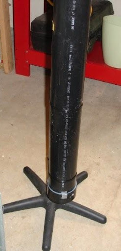
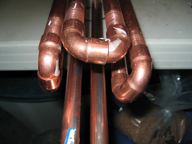
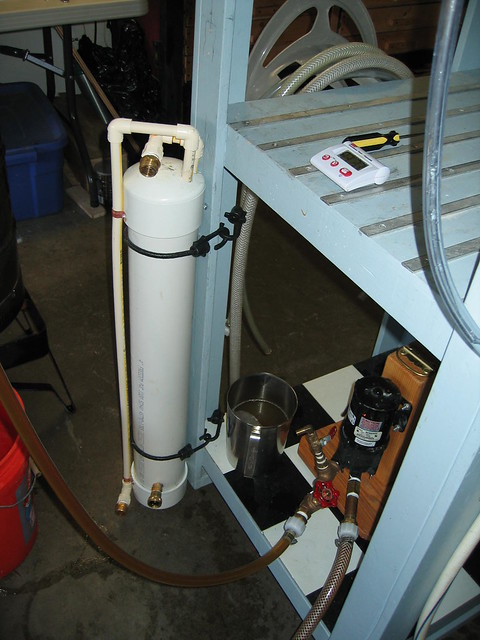
Looks pretty good! You could vastly improve the performance using a pump. You'll get the quickest chill with the cooling water at max flow rate. It appears that you built it using only six copper pipes, but your chiller is longer, so the total length is close to the 20 ft I have in the original. I also noticed you used double 90 elbows joined with a short piece of pipe. You can make tighter bends if you use one 90 elbow and one 90 stree elbow. This eliminates the need for the short joining pipe and makes for a more compact configuration. The advantage of doing it this way is that you can fit more pipes inside the PVC. Baffles aren't really necessary IMO. There's sufficient turbulence without them. I'm sure there are a number of ways to improve the design, such as using baffles and such, but I'm not nearly as sure that these would be worth the effort. Instead of using epoxy at the connections, I simply threaded the PVC for 1/2" pipe thread. The wall thickness of the schedule 40 PVC is heavy enough to make that work. Instead of a rack of some kind, I just bungee the chiller to my stand vertically. It takes up less space and keeps it out of the way. I don't have any connectors on the bottom cap though, so the end can rest directly on the floor. Post back after you try it out with an actual brew session.

That's a pretty nice rig I see in the background. You must have a pump on it. I'm wondering why you aren't using it to pump wort through the chiller.
 
Reviving and old thread. I like this idea and I might build one, has another else built one that I can take a look at? For a part list it sounds like. I like the idea of vertical mounting. Thinking I will run the hose in at the top and out at the bottom. The wort in and out in the middle in a coupler. Initially this would be for 10g batches, but want room to expand. Think I will go with 36".

4" PVC ~2-3 ft
1 4" pvc coupler
2 4" pvc end Caps
~30 ft 1/2" rigid copper tubing
Some PVC fittings for mounting the hose
think I could use some pvc glue or thread them in permanently
~8 copper street elbows
~10 regular elbows
1/2" copper to some sort of thread
to attach the wort hose
some PVC Cement or whatever the glue is called
make sure to get the primer/conditioner too
 
@milldoggy

It would be best to run the cooling water in at the bottom and out at the top. This way, the PVC water jacket will always be full and it will eliminate any possible air pockets. I run the wort both in an out at the top. There's little if any advantage to having the wort enter in the middle and doing it that way unnecessarily complicates the assembly.

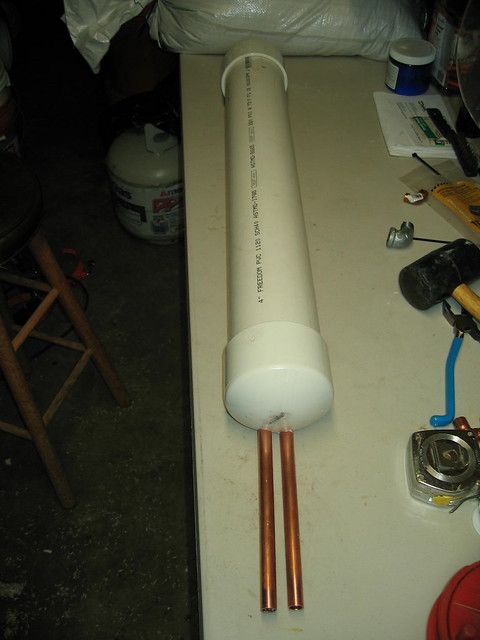
I did not glue the end PVC end caps in place. They are secured with two small sheet metal screws through the caps and into the PVC. The caps fit tightly and do not leak. I wanted to be able to disassemble easily it if need be.

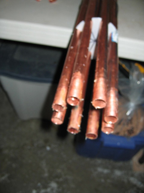
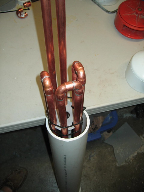
Here's the pics again:

4684633180_7c1e6dbea6_z.jpg


4684001647_dc84990572_z.jpg


4684891657_e0c180e571_z.jpg


4880832333_0760cec65e_z.jpg


Keep in mind that when full of water, this thing is heavy. The PVC is also fairly brittle, so you don't want to drop it. IOW, secure it well when in use.
 
very nice, thanks for the pics! How do you have the copper hooked to the pvc? How does it go through the cap? It looks like the hot wort is going through pvc into the copper, does that concern you?

Have you timed how fast you can cool your wort? I assume you are using the pump to recirc the wort. I plan om using a pump to recirc and whirlpool the colded wort back into the BK.

BTW, I have a black server rack, just like yours, I like how you used that as a shelve, might have to steal the idea.

1. I used adapters to go from the copper to the cpvc. The adapters are just inside the end cap, so they are not visible. I was concerned that the copper would conduct too much heat and possibly melt the pvc as is passed through the cap. This concern proved to be unwarranted. If I were to do it over I would just go with copper pipe throughout.

2. It's cpvc and rated for use in domestic hot water systems, so I have no concerns at all about using it with hot wort.

3. The cooling rate is very fast, but is highly dependent on the temperature of the cooling water. During the cold months my tap water is near 42F and I can cool 12 gallons to below 140F in about 4 minutes or so and to 100F in a about 6-8 minutes IIRC. The total time to reach pitching temps near 70F is about 25 minutes. IMO, it cools as fast as any and faster than most other chillers.

4. I also pump the wort in a continuous loop through the chiller and back to the kettle, so the cooling times mentioned are using this method. The idea is to approximate something like Jamil's whirlpool method, but using a CFC rather than an IC. This isn't truly a CFC, but more of a hybrid. My goal was a very high flow rate for both the wort and the cooling water for faster chilling.

I'm planning to add a pre-chiller for summertime brewing. It will be built much the same way only I will use a 5 gallon bucket instead of the 4" PVC pipe so I have room for the ice.
 
this contraption is huge... i do not see that advantage of this over a traditional counter-flow chiller. Is this unit really that much more cost effective than a traditional counter-flow chiller DIY build?

https://www.homebrewtalk.com/f11/cheycos-cfc-9395/

It's not as big as it appears in the pictures. It's only 30" long and about 5" in diameter. It contains 20+ feet of 1/2" ID hard copper pipe. It probably is not more cost effective than a traditional tube-in-hose counter Flow chiller, but IMO it chills faster due to the higher flow rate. I had a tube-in-hose chiller that took way too long to cool the wort and was pretty much useless when circulating back to the kettle with a pump. The cost to build this was about $50, but the copper prices may have gone up since then. I considered building a tube-in-hose type CFC using large 1/2" ID tubing and a very large hose, but abandoned that idea after considering how bulky it would be and how hard it would be to tightly coil the larger copper tubing without kinking it. I'm thinking about building another one with 10 tubes instead of 8 and shortening it up a bit. There's room to do that inside the 4" PVC. I'm thinking I could make it 24" in length with 20+ ft of 1/2" copper pipe inside. That would make it a little more compact and also a little more efficient, in theory anyway. Mounted vertically as I have it, it takes up very little space. Actually, considerably less space than my old tube-in-hose thingy.
 
Catt22, you say that you "will go with copper pipe through the cap". How? How to seal the pipe passage in order to prevent leaks?

BTW, Excelent pics and very good job!

Tks!
 
I think you could drill a hole, thread or glue in a pvc 1/2 coupler and force the copper through it. The compression of the pvc to copper might be good enough for a seal, if not, I am sure a little jb weld would work and a gasket of some sort on the copper and force the cap down till it seals.
 
Catt22, you say that you "will go with copper pipe through the cap". How? How to seal the pipe passage in order to prevent leaks?

BTW, Excelent pics and very good job!

Tks!

I bore the holes through the cap using a Forstner bit which makes a very clean and precise hole. The pipe fits very snugly in the hole. I used a small amount of silicone to make the seal just as BMB suggested. Also, the inlet and outlet fittings for the cooling water are threaded directly into the PVC pipe wall. The schedule 40 PVC pipe wall is quite thick and will accept threading with a pipe thread tap. No epoxy or glue other than that small amount of silicone sealer was used in this build.

Initially, I had the copper pipes coming through the cap like this:

4684892295_87a171da56_z.jpg


...but then I stupidly second guessed myself and made the transition through the cap with the CPVC. This was a blunder on my part. It works OK the way I have it, but it was not at all necessary to change it from the original copper penetration.
 
ok, last question. How do you get the wort stuck in the pipes out when you turn the pump off? Is there a considerable amount left in the chiller?
 
ok, last question. How do you get the wort stuck in the pipes out when you turn the pump off? Is there a considerable amount left in the chiller?

The volume in the pipes and hoses is only about a quart. I do not try to recover it. I brew 6 or 12 gallon batches with the goal being to get at least a full five gallons of finished beer into each keg. There will always be inevitable losses along the journey to the fermenter. Very little bugs me more than coming up short on volume at the end. I don't let that happen anymore.
 
Can I ask why you laid the pipes vertically rather than a long coil?

I like the neat and tidy design, but am trying to understand the benefits of one design over the other.

Thank you
 
Yettiman said:
Can I ask why you laid the pipes vertically rather than a long coil?

I like the neat and tidy design, but am trying to understand the benefits of one design over the other.

Thank you

I'd think this would be much more efficient as you'd have a longer run of copper exposed. Getting that tight of a could would be a challenge though.
 
Back
Top