Melted 40Amp FOTEK SSR

Homebrew Talk - Beer, Wine, Mead, & Cider Brewing Discussion Forum

Help Support Homebrew Talk - Beer, Wine, Mead, & Cider Brewing Discussion Forum:

This site may earn a commission from merchant affiliate links, including eBay, Amazon, and others.
Do you have any insight as to how the circuit and PCB compares to a "real" FOTEK?

A lot of "fake" electronics (non-SSR mind you) that I've seen go to the point of cloning the PCBs and putting in either factory seconds or cheap knock-off components. I wonder if the real FOTEKs are better designed or if they just use better components and assembly practices.
 
bu_gee:
I haven't disassembled any other SSR's, let alone good ones. All I have to rely on for insight is my EE background and the handful of other potted power electronics I've pried apart in the past.

As I referred to in the blog, at least in the realm of some of the encapsulated automotive assemblies I've fixed, there isn't as much of a PCB as one might expect. The power switches (MOSFETs in that case) are bare chips bonded to the back plate and wirebonded to termination tabs or frames molded into the case. This directly addresses the capacity and reliability of both the current and thermal paths involved. I do recall seeing some promotional quips about "direct bonding technology" or somesuch from Gavazzi materials, but I can't be certain that's exactly what they're referring to.

Still, if the FOTEK product pdf is to be taken as truth, the circuits are necessarily dissimilar. At the very least, the input circuit I observed cannot meet the specifications in the pdf. It should also be pointed out that at least among the material I've seen, FOTEK doesn't even make a 60A part.

If the triacs were matched or ballasted sufficiently to operate in parallel, there wouldn't be much change required to make my relay into a serviceable 50A SSR. In the end, it's not capable of 60A or triggering at 5v in any case. Therein lies the problem. It's not that the cloned parts are inherently garbage or anything. They may have a certain region of safe and reliable operation, but the problem is that if specifications are untrustworthy and the details of the construction are unknown, the user has no means to responsibly apply the part within its actual capacity.
 
I noticed that article too, though only in the aftermath. For what it's worth, mine has a squared recess with rounded corners on the label. Mine doesn't say Taiwan on it.

well my two "fotek " labeled ones have the rounded corner cut on the sticker but the plastic indentation for that corner is supposed to be rounded as well and mine arent... my "mypin" branded one is indentical to my foteks in every way including the markings on the back... one of my foteks say "made in Taiwan" and the other does not but one is labeled for 25a and the other 40a... they all work fine anyway and two have 35 brews or so on them now. (they only see a 19a load maxx though)
 
It's interesting that you mention the markings on the back.

One of the things I noticed about the SSR when I got it was the backplate. Granted, I haven't seen a real FOTEK, but the backplate on mine was not what I would consider reasonably flat for a thermal interface surface. It might be interesting to see if the characteristics of the backplate (finish quality, laser markings, screws) can be used for identification of fakes, though I don't hold hope that techniques based on appearance will help when shopping online.

Assuming all the fake FOTEK's are built similar to mine, I wouldn't be too worried about the legitimacy of your FOTEK's at that loading -- especially for a 25A/40A configuration. Even if they're fakes, they're probably built with single triac outputs.

Of course, pictures of melted terminal barriers makes me want to say that all of this still requires the standard measures for proper operation. That is: a proper thermal path and terminal torque. That includes the understanding that long cycle time settings tend to loosen wire terminals due to thermal cycling (which is sort of a self-exacerbating process).
funny thing is the pics of a real fotek back plate showed a number ending in "TW" indicating it was made in Taiwan... my spare says "HK" after the number on the back while it says "made in Taiwan" on the front.... to me HK indicates Hong Kong china...
 
One other thing I thought about while prepping things for my new relay was the consequence of the device structure on the junction-case thermal resistance.

It's obvious from the testing and visual checks of the triac internal structure (they were broken during disassembly) that these are insulated tab variants of the CTA24/BTA24 triacs. Considering a junction-case thermal resistance of 1.7 K/W and an interface thermal resistance of about 0.20-0.25 K/W for the TO220 insulated tab packages, the overall junction-case thermal resistance for the SSR could be as much as 0.975 K/W -- let's just say 1 K/W.

Considering that most of the other 50A SSR's (Gavazzi RM series, etc) I've looked at have a RTjc of about 50-60% of this value, one might use a lot more caution when sizing heat sinks for cheap SSR's. The heat sink selection guidelines or calculators from other SSR manufacturers might be misleading by a huge margin. When it's the thermal resistances internal to the assembly that are significant, it may be difficult to notice an excessive operational condition; the heat sink temps would remain relatively low. Overheating would indeed contribute to the likelihood of a stuck relay.

I'm wondering why bother with the SSR when a very simple triac circuit will to exactly the same thing? Also Triacs are just two back to back SCRs with a common gate. SCRs are available in many current capacities..... Two SCRs, one Triac, one triac and a suitable gate resistor, two SCRs and a suitable gate resistor. mount two SCRs of a suitable capacity on a good large aluminum or copper heat sink. Anytime something is "potted", you end up with an additional thermal interface. The internal junction, and the external one. By assembling it yourself, you eliminate one of these, and that's a plus!

I use triacs in place of expensive relays / contactors frequently.

H.W.

Makes sense if you have the knowledge and skills to pull it off. The main advantage of a SSR is the package. Simply bolt the thing to a heatsink (or back plate) and screw down you control wiring and power wiring - job done with nothing more than a screwdriver.
 
I'm wondering why bother with the SSR when a very simple triac circuit will to exactly the same thing? Also Triacs are just two back to back SCRs with a common gate. SCRs are available in many current capacities..... Two SCRs, one Triac, one triac and a suitable gate resistor, two SCRs and a suitable gate resistor. mount two SCRs of a suitable capacity on a good large aluminum or copper heat sink. Anytime something is "potted", you end up with an additional thermal interface. The internal junction, and the external one. By assembling it yourself, you eliminate one of these, and that's a plus!

I use triacs in place of expensive relays / contactors frequently.

H.W.

Well, of course it would be relatively simple to essentially make my own SSR -- because with optoisolation, that's functionally what it would be. The packaging of a quality commercial SSR is certainly a convenience for mounting and termination. For inexpensive triac relays, it's hard to compete economically either.

Disregarding the convenience advantage isn't an option for a lot of people. The flexibility of a custom design doesn't just require design knowledge; it requires extra tools and assembly experience. It also requires extra time and effort, and introduces new sources of problems (though the thread topic shows that cheap SSRs do that too).

SCR's as you suggest would be the route to go for anything custom. Above 40A, they're pretty much the only option. Beyond that point, sky's the limit for available voltage and current capacities. SCR/SCR modules can help gain back a bit of packaging/termination convenience and modularity in a custom design and still keep RTjc low (0.1 K/W for a 400V 210A module configured antiparallel)

But don't tempt me to go custom. I'd be tempted to move entirely away from on-off control once switches and triggers are independent. I'd have the entire thing phase controlled. I bet the AM radio fans in the building would love me.

This stuff isn't "rocket science".... It's stuff anybody could do. Not a circuit board with dozens of components, just 3 parts that can be mounted to a heat sink directly for optimal heat dissipation. And relatively bullet proof parts at that.

H.W.
 
This stuff isn't "rocket science".... It's stuff anybody could do. Not a circuit board with dozens of components, just 3 parts that can be mounted to a heat sink directly for optimal heat dissipation. And relatively bullet proof parts at that.

H.W.

To many here running a 220v line is rocket science....
 
two scr's, optotriac, snubber network, maybe five resistors... I'd certainly use a printed board.

I'm not a fan of dead bug assembly -- at least not for mains interfaces.
 
two scr's, optotriac, snubber network, maybe five resistors... I'd certainly use a printed board.

I'm not a fan of dead bug assembly -- at least not for mains interfaces.

I presume you mean a project board........... It's hardly worth printing a board for something like that. I assume your use of the optotriac it to isolate the PID...... a good idea.

H.W.
 
I presume you mean a project board........... It's hardly worth printing a board for something like that. I assume your use of the optotriac it to isolate the PID...... a good idea.

H.W.

Not just a good idea. Line voltage will be on the gate and blow the PID controller without it.
 
Not just a good idea. Line voltage will be on the gate and blow the PID controller without it.

How's line voltage going to be on the gate?? The PID outputs 5 volts.......... My concern would be that if one of the SCRs should "blow", you could end up with line voltage feeding back to the PID.


H.W.
 
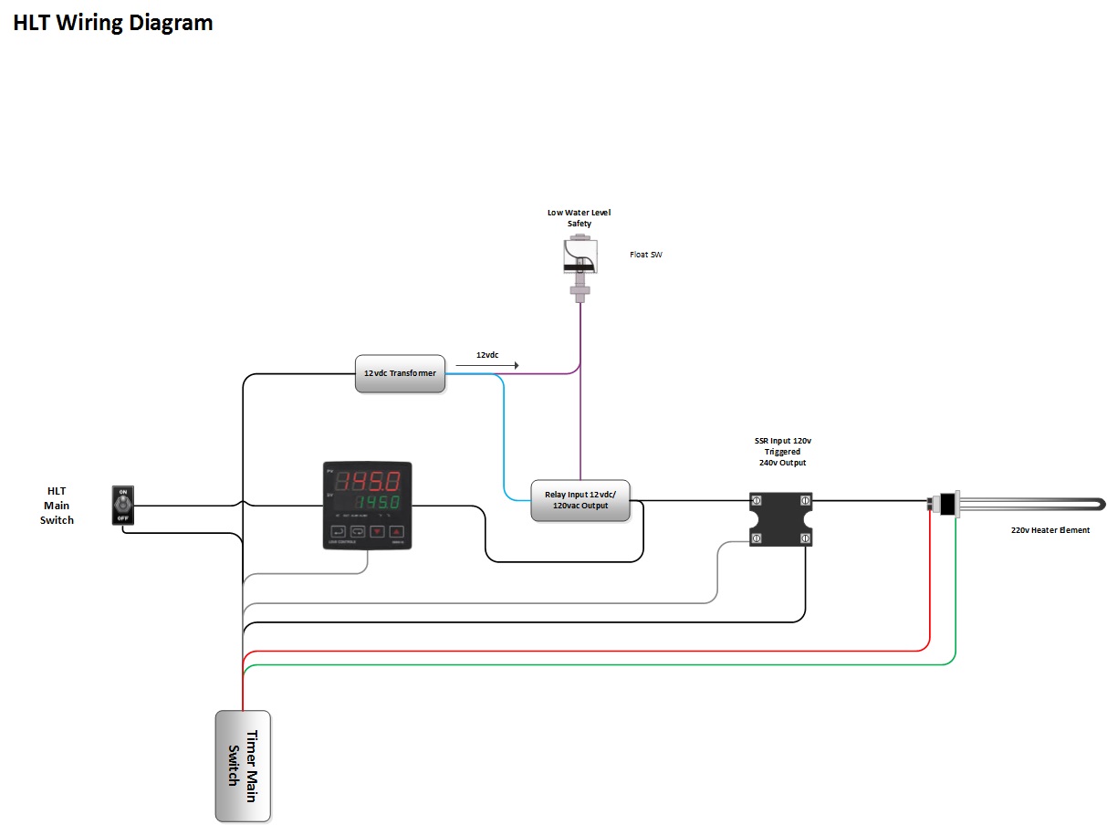
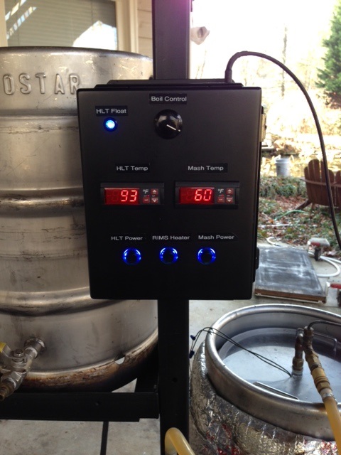
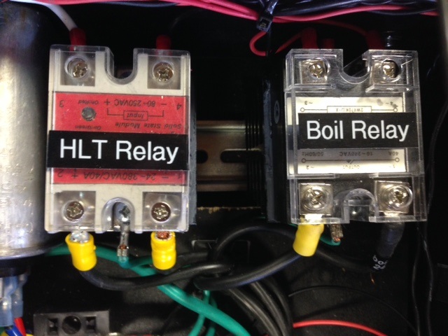
I recently converted my brew stand to total electric. Before the HLT and RIMS were both electric 110v. I converted the HLT and Boil kettle to 220v. I have Love TS temp controllers that I use to control the temp for the RIMs and the HLT. In the case of the HLT the 110v output of the Love controller is used to trigger the Fortek 40amp SSR (SSR-40AA AC-AC 40A 80-280VAC 24-380VAC ). What I have noticed is my HLT continues to heat up even after the Love controller de-energizes the trip side of the relay. It appears to be sticking the only way to fix it is hard power cycle the main power and then it works properly the rest of the day turning on and off properly until the next brew day when I have to do the same procedure again (power cycle). See attached wiring diagram and a couple of picture of the panel. I do not believe I wired anything wrong especially if power cycling fixes the issue. I also use an SSR I got from StillDragon to control the boil I have no issues with it but it is a different manufacturer. Any help would be appreciated.

hlt wiring.jpg


control panel.jpg


relays.jpg
 
What I have noticed is my HLT continues to heat up even after the Love controller de-energizes the trip side of the relay. It appears to be sticking the only way to fix it is hard power cycle the main power and then it works properly the rest of the day turning on and off properly until the next brew day when I have to do the same procedure again (power cycle).

I can't decipher your schematic, but i'll trust that it's right if everything at some point does work. Disregarding details, the one thing i would verify is that the SSR output is indeed "closed" at the same time the input is not present. When it's locked up, check for voltage on the input terminals. If the control signal is ~0v and the output stays latched, you might consider replacement. It may be that the cold current associated with starting the heater causes enough internal heating to lock up the output triac. A triac output relay is susceptible to lockup when operated beyond reasonable conditions. Some of the fake SSR designs put the triacs well into unreasonable operating conditions at the rated current. I don't know what sort of steady state or inrush current is associated with your heater, what sort of thermal path has been provided, or whether your relay is genuine, so it's just a guess.

Regardless of the particulars of why it's failing, it shouldn't be latching on without an input present. If indeed it is, it probably needs to be swapped with something trustworthy.

I only notice now how old this post is. Oh well.
 
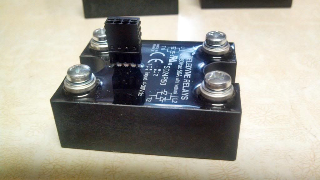
I'm running some 50-amp dual channel Teledyne relays. They are pretty awesome. I was originally going to go with the cheap foteks like most people but I found these for $14 each with the fancy 4-pin connector for the 5v control voltage. They are potted and everything. The studs are for high voltage and the 4-pin is the control wiring. Each side is essentially its own relay. I use one of these for both of my pumps. Good deals can be found if you loom around. I think it is better to buy it once. This all assumes that your panel is wired correctly too.


currently $15 on ebay.
 
I had the same issue with Floteks. I bought some of the Teledynes shown in the previous post and haven't had an issue since. No matter what you use, keeping them cool with a good heatsink and preferably a small fan is important.
 

Latest posts

Back
Top