3 Phase power questions

Homebrew Talk - Beer, Wine, Mead, & Cider Brewing Discussion Forum

Help Support Homebrew Talk - Beer, Wine, Mead, & Cider Brewing Discussion Forum:

This site may earn a commission from merchant affiliate links, including eBay, Amazon, and others.
If I set it up with out individual control I will have a lower amp draw though correct?

No, that's not really true, the amperage draw per phase is directly related to the element draw. Each phase has two elements drawing on it, unless you switch one off, then the two associated phases would have their draw reduced proportionally.

Glad to help.
 
Interesting project ... a few questions/comments ...

Should the element CB's be upstream of each SSR?
Are you required to interrupt all non-grounded conductors to the load?

I think the not exceeding 80% of the breaker rating applies for 'continuous loads' (energized for three hours or more). Or you can get 100% rated breakers?
 
Glad you are all having fun.

I'm still trying to wrap my head around the current draw on 3 phase delta power. The calculation formula is knocking me down.

I think it is this for 3 - 5500W elements rated for 240V. Each element draws 22.9A - times 1.73 = 39.6A per phase.

Is this correct?

I'll put the diagram back up as soon as I can get it figured out correctly and drawn properly.

P-J

Maybe team up with one of the other guys who chimed into this thread and hammer this one home.
 
Glad you are all having fun.

I'm still trying to wrap my head around the current draw on 3 phase delta power. The calculation formula is knocking me down.

I think it is this for 3 - 5500W elements rated for 240V. Each element draws 22.9A - times 1.73 = 39.6A per phase.

Is this correct?

I'll put the diagram back up as soon as I can get it figured out correctly and drawn properly.

P-J

If the elements are rated 5500 W at 240 V, then that is what they will dissipate with 240 volts applied whether the power is single phase or three phase. Each element has 240/R amps where R is the resistance of the element. But each line coming into the delta has a current of 1.73 times the current in each element because the currents are out of phase, so some current adds and some subtracts from the current in each element.

One way to calculate it is to draw a phasor diagram - x and y axes with three phasors from the origin at 120 degrees apart. Each phasor represents the current in one of the elements. The current in the lines is the vector difference of two of the phasors. For example, take a phasor of magnitude i at 0 degrees and another of magnitude i at 120 degrees. The first one has x component of i and y component of 0. The second has x component of -i/2 and y component of i*cos 60º which is equal to i*sqrt(3)/2. To find the vector difference, we have an x difference of i - (-i/2) = 3*i/2 and a y difference of i*sqrt(3)/2. The magnitude of this difference vector is given by the square root of the sum of the squares of the components:
I = sqrt(9/4*(i^2) + 3/4*(i^2)) = i*sqrt(12/4) = i*sqrt(3) = 1.73*i
 
Try this:

208-3-phase-WYE
208-3-phase-WYE.jpg


240V-3-phase-Delta
240V-3-phase-Delta.jpg

After reading all 5 pages of this I decided to throw my 2 cents into the mix. These drawings are the 2 most likely power distribution systems you are likely to find in a commercial 3 phase system. Industrial 3 phase is a completely different animal and not an issue here. P-J's second diagram is the odds on favorite to show what you are most likely dealing with. This split phase 240 Delta system is what is installed in most Wal-Mart's, Home Depot's, etc. It provides maximum versatility to the building occupants as far as what loads they wish to use. It is a simple check with a meter to determine what you actually have, but I would bet on this one. My employer thinks I am qualified to answer this question, as he pays me to teach and train my employees how to work on this kind of stuff without getting dead. So far so good.
 
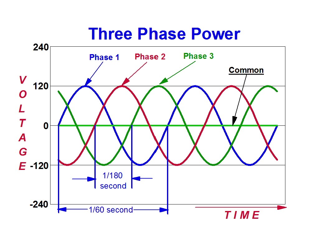
I always like to draw it. AC power is a wave - in the US it's a wave with 60 cycles per second. Each leg of a three phase system is 120 degrees out of phase - so the waves don't line up. If you connect any two waves the total voltage isn't twice a single leg - since the waves aren't lined up.

3+PHASE+WAVE+FORM+3.jpeg


here's a graph of 120v 60 Hz three phase. If you measured from peak to peak on any one phase it's 120v. However, and here's where the math comes in, since the waves aren't in phase (lined up) the sum of two phases isn't twice - it's 1.73x.

so, when you look at the highest combined voltage of any two phases you see +104 / -104 for a total of 208.

3phasegraph.jpg


is that helpful?
 
UGGG!!! My head hasnt hurt this much since I was going through Basic Electrical and Electronics back in the Navy......

Lets get back to brewing beer and save all the 3-phase theory talk for a different site!

OKAY rant over, brew on.....
 
UGGG!!! My head hasnt hurt this much since I was going through Basic Electrical and Electronics back in the Navy......

Lets get back to brewing beer and save all the 3-phase theory talk for a different site!

OKAY rant over, brew on.....

But you're in the Electric Brewing forum :) You gotta have fun with the theory sometimes.
 
I always like to draw it. AC power is a wave - in the US it's a wave with 60 cycles per second. Each leg of a three phase system is 120 degrees out of phase - so the waves don't line up. If you connect any two waves the total voltage isn't twice a single leg - since the waves aren't lined up.

3+PHASE+WAVE+FORM+3.jpeg


here's a graph of 120v 60 Hz three phase. If you measured from peak to peak on any one phase it's 120v. However, and here's where the math comes in, since the waves aren't in phase (lined up) the sum of two phases isn't twice - it's 1.73x.

so, when you look at the highest combined voltage of any two phases you see +104 / -104 for a total of 208.

3phasegraph.jpg


is that helpful?

Nice diagrams and very helpful, but I do have one minor nit to pick. You are showing the peak voltage as 120 volts - actually that is the RMS (root mean square) value, so the peak should be about 170 volts, not 120, or a peak of about 340 for 240 volts RMS.
 
My keg has waves in it when I move it using the power of my arms. If I have three kegs and move them all, do I have three phase power? How many elements can I heat with my three phase waves? Do I have to multiply or divide the rms of the wave height by root 3? Or am I just getting confused?
 
Nice diagrams and very helpful, but I do have one minor nit to pick. You are showing the peak voltage as 120 volts - actually that is the RMS (root mean square) value, so the peak should be about 170 volts, not 120, or a peak of about 340 for 240 volts RMS.

yeah, not my diagrams, but they illustrate the point.

I teach lots of people coming into the entertainment industry about three phase 120/208 power. I always find myself sketching the phases out on scrap paper - these were the first links I found on the interwebz to illustrate the point. :)
 
I have 240VAC 3-phase in my house, and over here (Norway) that's pretty normal. As others have pointed out, the way to calculate max power draw from one breaker is:
P = U x I x sqrt3 where P is Power, U is voltage, I is current and square root of 3 is approx 1.73.

If you have a 50A breaker, the max power you can have on that breaker will be: 240V x 50A x 1.73 = 20784Watts

If you divide that by three elements, each element can have a maximum power of 20784 / 3 = 6928W pr element.

The other way around: three elements 240V 5500W connected in delta, each element will see 240V and total power will be 3 x 5500W = 16500W

Breaker needs to be: I = P / (U x sqrt3) = 16500W / (240V x 1,73) = 39.7A

Each element on it's own, connected to either to legs of the 240V three-phase vill draw 5500W / 240V = 22.9A. (if multiplied by sqrt3 is equal to 39.7A in the last example)

In my service panel the three phases of 240V is divided equally(-ish) between all the subcircuits giving single-phase 240VAC (or as it is more correctly called in the school books nowadays dual phase 240V).

No 120V over here, only between one hot leg and ground, but ground fault circuitry will cut power in main breaker if a current draw above 30mA is seen from hot leg to ground.
 
Protto said:
Breaker needs to be: I = P / (U x sqrt3) = 16500W / (240V x 1,73) = 39.7A

Don't forget to divide by .8 to find the actual breaker size, which in this case would be 49.6A, rounded up to 50A. If you don't, expect to replace the not too cheap 40A three phase breaker in a year or two when you could have just got a 50A and been good for life.

Another way to do it would be to get a 100% rated 40A breaker, and you could reduce the wire size, but they are pricey. If you have a lot of wire length to run, it can become cost effective... Would have to crunch your own math and get pricing to figure out.

True. The formula only illustrates the actual current drawn by the elements.

How to get the right size breaker and even cable may vary from house to house, or at least country to country.

At least in my country it is not given what cable size you can use on a certain breaker size, it must be calculated according to cable length, short circuit current in the main panel etc.

If you oversize the breaker, everything down the line have to be sized to handle the power the braeker can deliver.

This should be left to a pro. of course.

That said, a normal 16A breaker in my hose (pretty normal size over here) can give 16A continous in most cases. It can even give more, for a while. There are also different types (i.e. fast, slow) and the slowest can take some overcurrent for an hours boil no problem.
 
You Europeans and your funny electrical setups, ;) that's actually pretty cool. Funny how things we take for granted are so different between countries. We can't really get (unless you want to pay big bucks or have a large electrical service) breakers with different trip sensitivity. If you want that, you have to use fuses.

To specify, that .8 divider would apply to North America. You'd have to consult local electrical code for the wire size based off that breaker. And/or a local electrician.
 
Correct me if I'm wrong, don't you have 230/400 50hz 3phase over there in norway. You have 230volts line to neutral and 400volts line to line? If I was doing an electric brewery on that nominal voltage I'd use 480volt (common usa voltage for industry) water heater elemets, its not as common as household 240 volt elements, but you could get way more watts without increasing your wire size. maybe even do double batches without changing your feeder circuitry.
 
Correct me if I'm wrong, don't you have 230/400 50hz 3phase over there in norway. You have 230volts line to neutral and 400volts line to line? If I was doing an electric brewery on that nominal voltage I'd use 480volt (common usa voltage for industry) water heater elemets, its not as common as household 240 volt elements, but you could get way more watts without increasing your wire size. maybe even do double batches without changing your feeder circuitry.

You are not wrong ;) It's pretty common in new houses, or at least in newly developed areas that the power company gives you 400V 3-phase with neutral. Than you get 230V between any hot leg and neutral.

The grid I'm hooked up to is a 230V 3-phase, no neutral conductor. (i get 240V, live close to the transformer). This is also very common, but not in newly developed areas.

All this depends on how the transformer on your grid has it's secondary windings set up. Y or delta.

It's very nice to have 3.7Kw out of a single phase 16A breaker using 2.5mm2 wiring. And I agree 480(or 400 in my case) vould be nice in the brewery to save wiring and equipment size.
 
Here's what I think are the voltage and currents. Notice how the line current and element current is 30 degrees out of phase. Also the terminal voltage to "neutral" multiplied by line current is the same as the element voltage multiplied by the element current (same power) as it of course must be.

EDIT: This is for the elements connected in a delta configuration, 240 v line to line.

3-phase delta current flow.jpg
 
All,

I'm still confused beyond belief.

I just put the original diagram back in place (page 2).

I drew the diagram for using 240V 3-phase power (240V Delta transformer) as the system input.

When I illustrated the wiring within the controller, the elements are connected in a 'Y' configuration. This resulted in the actual voltage presented to each element as 208V. The elements chosen for the diagram are 5500W-240V.

Now after doing days of digging through my mess, I think I understand that I will need 40A breakers instead of the 30A shown. Each element will be drawing 19.95A, so for the set of 3 elements they will draw a total 34.34A per line from the 240V Delta power input.

I think.

Damn... I'm still confused.....

I'm have one hell of a time wrapping my mind around it all.


P-J

240-208-3phase-delta-wye.jpg
 
All,

I'm still confused beyond belief.

I just put the original diagram back in place (page 2).

I drew the diagram for using 240V 3-phase power (240V Delta transformer) as the system input.

When I illustrated the wiring within the controller, the elements are connected in a 'Y' configuration. This resulted in the actual voltage presented to each element as 208V. The elements chosen for the diagram are 5500W-240V.

Now after doing days of digging through my mess, I think I understand that I will need 40A breakers instead of the 30A shown. Each element will be drawing 19.95A, so for the set of 3 elements they will draw a total 34.34A per line from the 240V Delta power input.

I think.

Damn... I'm still confused.....

I'm have one hell of a time wrapping my mind around it all.

P-J

P-J, with 240 volts across the legs of the wye, the line to neutral voltage is only 138.6 volts; i.e., 240/sqrt(3), not 240*(sqrt(3)/2)).
 
P-J, with 240 volts across the legs of the wye, the line to neutral voltage is only 138.6 volts; i.e., 240/sqrt(3), not 240*(sqrt(3)/2)).
Awwww... Crap! Damed if I didn't blow it again.!

This whole thing is a pain to my brain.
Getting old just plain sucks.

I just posted a note on the smaller front diagram of my post on page 2 (this thread). I left the large image in tact.

So, now with all of that, I drew a new diagram that is hopefully correct. The power configuration is still 3-Phase 240V but is now a Delta - Delta configuration. Hopefully I also figured out the correct amperage required for each Phase that must be delivered.

Thank you all for putting up with my stupidity.

First thing is the basic power layout to the elements.

240-3phase-delta-delta.jpg


Next is the diagram redrawn for a Delta - Delta wiring layout.

And - As always - Click on the image to see a full scale diagram printable on Tabloid paper (11" x 17")


All: Please let me know if I fixed some of my mind twists and got it correct this time.

Thank you all for your patients with this old man (Now just 3 months shy of 73).

Thanks!

P-J
 
I think colors around the ssr and the elements are a little bit confusing. It would be a little easier to follow if the same color phase came in and out of the ssr and the wires going to the elements were opposing phase colors. The color configuration of Black, Red, Blue is the common 120/208 wye colors in the US. But when running 120/240 Delta you will have a high leg (approx 210v line to neutral) this leg is not to used for line to neutral loads, but it must be identified by being colored orange or tagged as being the high leg. Typically it is placed in the center phase in a panel. (Some places go black, orange, blue. Others use Black, orange, red.) I would recommend placing a note in the schematics to make damn sure that was not the leg that was feeding your pumps and controls. Besides that, looks pretty good.

Grandequeso

Grandequeso,

Thank you so much for your guidance. It is very much appreciated.

I redrew the diagram (above in post #64) with the changes that you suggested. I ended up using orange for the high leg and then chose blue and red (instead of black and red) which made my life a tad easier redoing the diagram.

You helped clear up a lot of confusion spinning in my head.

Thanks.

P-J
 
Reviving this thread, P-J, are you confident in that above diagram? I PMed you with some updated info. I would like to use this same setup but in a 208v setting with 6000w elements. Thank you.

Anyone else have luck with this yet?
 
Reviving this thread, P-J, are you confident in that above diagram? I PMed you with some updated info. I would like to use this same setup but in a 208v setting with 6000w elements. Thank you.

Anyone else have luck with this yet?
Just sent you a PM. Finished a diagram with your latest specks and would like to e-mail it to you to see if it fits your needs...
 
Sorry, I don't mean to offend Huntb, but that is entirely incorrect. You are showing single phase wiring, and it's incorrectly labeled.

Cruelkix, I've built three phase control panels before, and it's not that hard to do. A fully variable controller with individual element selectivity and control and PID integration is as complicated as I've built yet, but it works. One thing you will need to do is run three elements per 3ph circuit. You state you want to run 6 5.5kw elements, where would each element be?

If you are interested in what a 3 phase panel could look like, here's one I built not long ago.

View attachment 72501

View attachment 72502

Hello,

Tried accessing your site, no success. I'm interested in a 3 phase one PID two Elements controller.

Could you get in touch?

Thanks.
 
It would help if you made a new post with details like what voltage how much power you need.
Thanks for your response. I hope this will do.

Pot (water) volume: 80l
Voltage supplied is 415 V 3 phase.
Power needed: 18 kW.

In terms of heating element, I'm considering the round heating types like the ones sold by Brewpi.

Thanks.
 

Latest posts

Back
Top