Testing a 240v control panel with 120v

Homebrew Talk - Beer, Wine, Mead, & Cider Brewing Discussion Forum

Help Support Homebrew Talk - Beer, Wine, Mead, & Cider Brewing Discussion Forum:

This site may earn a commission from merchant affiliate links, including eBay, Amazon, and others.

LandoLincoln

Well-Known Member
Joined
Feb 15, 2011
Messages
2,978
Reaction score
1,143
Location
Joliet
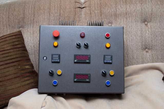
So I finally completed my 240v 50a control panel, but it's going to be a month or two before I get the 240v 50a service set up in my basement, and I'm really curious to see if everything is working okay on my control panel.

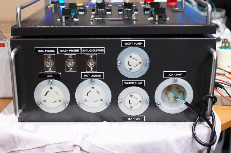
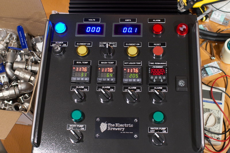
I don't need to test the element outlets, I just wanted to make sure that the contactors and switches and PIDs and pump outlets were working as they're supposed to.

The contactor coils are all 120v as well, btw.

So...yeah...I don't think that there would be anything wrong hooking this baby up to a 120v 15a GFCI cord, splitting the hot wire to run into both hot lines of the 240v system and plugging it into the wall. Since I'm not running any elements at this time, there's no need for 240v service.

Right? Or should I just cool my jets and wait?
 
Perhaps you could smoke out an issue, but my view is that there will be so much reconfiguration that there will be limited value. You will have to retest when you get your 50a service, regardless. But it's your panel, so proceed if you like.

One specific question: How will you put a load on the SSR's so you are not confounded by SSR leakage?
 
I don't know what there would be to reconfigure. I don't have any lights that run on 240v. Nothing is 240v except for the power going to the elements, which I'm not going to be testing.

I really don't know much of anything about SSR leakage. I guess I have more reading to do.
 
It'll depend a lot on your setup, I tested mine (also a 240v, 50a) on 120 before I moved it to it's final spot. On my setup, all the 120 comes from a single leg, so I just powered that leg and left the other unpowered and tested from there.

SSR leakage won't be an issue unless you are indicating element status from the AC side of the elements. Since you said you don't have 240 items, I'll assume you don't have element lights (it's really the only way to get them to work on the a/c side) Essentially what happens is when you don't have the elements hooked up to provide a load, there is residual current that's enough to make the indicators glow. On my setup, when I don't have the element connected, the light glows about a 1/3rd as bright as normal.
 
I agree that you could test all of your 120v devices by connecting a 120v hot to the hot bus that feeds them, and the neutral to your neutral bus. You would then defer the testing of your 240v devices (SSRs and elements) until you have your 240v service. If you are getting antsy, go for it. :)
 
Could you just get a temp 30 amp 2 pole breaker?
I'm testing mine right now using a temporary non GFCI 240 v breaker. I set everything up right next to my panel and wired in a 4 wire dryer cord to power my control box, got my multi-meter out and my voltage detector and went through switches to make sure all was kosher.
 
IMO the only useful testing you can do with 120 VAC is the control functions of contactor coils, PID, and the other low voltage systems.

As Jeffmeh points out, the 240 volt power circuits can only be realistically tested when your 240 supply circuit is ready.
 
IMO the only useful testing you can do with 120 VAC is the control functions of contactor coils, PID, and the other low voltage systems.

As Jeffmeh points out, the 240 volt power circuits can only be realistically tested when your 240 supply circuit is ready.

That's exactly what I wanted to test. But I've decided to just cool my jets and wait it out until I have everything ready. But thanks for all of the input, fellas!

20130426img7805.jpg

"I'll just sit here on the couch and wait. Take your time."
 
Did you say you were going to split the 120v hot lead and connect that to the two hot leads of the 240v? That would result in a direct short, the hot leads of a 240V system are both 120V but 180 degrees out of phase so the difference is 240V.
 
Did you say you were going to split the 120v hot lead and connect that to the two hot leads of the 240v? That would result in a direct short, the hot leads of a 240V system are both 120V but 180 degrees out of phase so the difference is 240V.

Actually it will result in - nothing. Anything 240 hooked up will just see 0 V across the hots, and 120v to ground / neutral.
 
Your're right, I realized that as soon as I posted. Either way though its probably not a good idea. An ohmmeter and a triple check of the wiring to the diagram should be all that is needed. Although powering up an incorrectly wired panel will let you know where the problem is instantaneously.
 
yup, meter everything out first. but a power on check doesn't hurt. when I did mine I realized I had the pumps and lights flipped on the wiring - forgot to mirror things when I wired from the backside.
 
Your're right, I realized that as soon as I posted. Either way though its probably not a good idea. An ohmmeter and a triple check of the wiring to the diagram should be all that is needed. Although powering up an incorrectly wired panel will let you know where the problem is instantaneously.

Yes, I tested all of the circuits. I just wanted to see the pretty lights and hear the contactors click open and closed. But I'm going to wait.
 
I don't know what there would be to reconfigure. I don't have any lights that run on 240v. Nothing is 240v except for the power going to the elements, which I'm not going to be testing.
If your panel is like my documented design(s) then yes, you can test it easily with a standard 120V / 15A outlet without any rewiring required. This is possible since all the devices inside are 120V. The only devices that require 240V are the heating elements.

You simply need to hook up the 3 wires (120V HOT, NEUTRAL, and GROUND) correctly.

I tested my 30A panel exactly like this back when I first built it:

IMG_1476.jpg


Disclaimer: This is for testing purposes only. Even safer would have been to attach the 120V/15A power cord to the 30A locking connector (instead of how it attached above) so that I could plug it/unplug it saftely.

Kal
 
You do see 0V on the voltmeter however as someone above pointed out:

IMG_1475.jpg


IMG_1477.jpg


But everything still works. You can test everything but the voltmeter and heating element receptacles.
The pumps will even work.

Kal
 
Back
Top