
theveganbrewer
Well-Known Member
and it Looks like this.
I made the box from AZEK.
Im just testing it now, nothing to brew right now. But in a week or 2, I will be using it in the fridge
Is that a double outlet off one controller? Dang, I should've thought of that

") ha
ha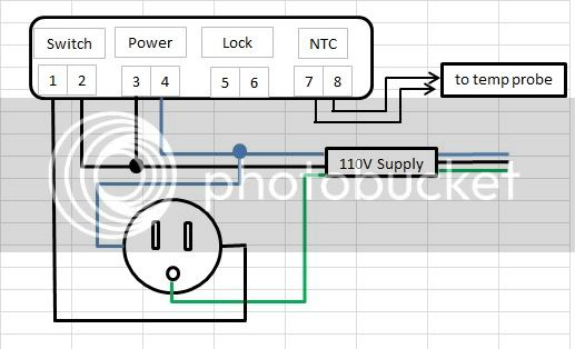
.JPG")
.JPG")
.jpg")
