That's good info. Just FYI - for the self tapping screws on my build, I'm only attaching light weight things like power outlets, pumps, therminator, etc. The screws ARE NOT used for anything structural or weight bearing (with the small exception of my new tippy dump, but that also has 4 screws per hinge).Tapped holes generally should have 2 to 2-1/2 threads engagement.
You are using an out of date browser. It may not display this or other websites correctly.
You should upgrade or use an alternative browser.
You should upgrade or use an alternative browser.
Need help picking steel for a brew rig
- Thread starter CidahMastah
- Start date

Help Support Homebrew Talk - Beer, Wine, Mead, & Cider Brewing Discussion Forum:
This site may earn a commission from merchant affiliate
links, including eBay, Amazon, and others.
CidahMastah
Well-Known Member
- Joined
- Nov 12, 2010
- Messages
- 4,201
- Reaction score
- 46
I think the old, "common sense goes a long way" phrase applies here.
Good info - I really like knowing the standards on these things, even if you have to bend the rules every now and then like with Jon's tippy install
Good info - I really like knowing the standards on these things, even if you have to bend the rules every now and then like with Jon's tippy install
microbusbrewery
Senior Member
Ditto. I'm working on my build right now and I'm using 1.5" 16 gauge. Structurally speaking, 16 gauge is plenty strong but I wouldn't trust it for tapping threads. I ended up welding a nut on if I needed threads for attaching something (I think just the casters if I remember correctly). The only exception is my control panel that sits on top of a bracket, I used self tapping sheet metal screws to secure it, but since it sits on top of my bracket the screws simply hold it in position.1/8 inch thick is probably the minimum thickness that could reliably be tapped, so enough screw threads would be present to hold the screw and whatever your attaching safely.
CidahMastah
Well-Known Member
- Joined
- Nov 12, 2010
- Messages
- 4,201
- Reaction score
- 46
I just looked at some 14G 1x1 steel this weekend and an old timer steel tradesman said I was crazy to go any bigger than 1x1 in 14g sizing. He claimed that it wouldn't bend under the pot load I described if I put in gussets.
Anyway, I am thinking about trying to loko at some 2x2 or so 14g instead of the 11g. I am concerned that the stand will be insanely heavy for no reason. Thoughts on this?
Anyway, I am thinking about trying to loko at some 2x2 or so 14g instead of the 11g. I am concerned that the stand will be insanely heavy for no reason. Thoughts on this?
I think the common usage of 2x2 is to give a better footprint for the kettles, not the strength. If you're using 1x1 and gussets, then you may be able to increase your footprint for the kettles without needing 2x2, but I liked the available footprint with 2x2.
It is not insanely heavy at all. All my wiring is under my stand, so if I want to make additions or changes, I just flip my stand over.
It is not insanely heavy at all. All my wiring is under my stand, so if I want to make additions or changes, I just flip my stand over.
CidahMastah
Well-Known Member
- Joined
- Nov 12, 2010
- Messages
- 4,201
- Reaction score
- 46
I really want to stick with 2x2 for several reasons (one in particular being... I don't want to have to put in gussets). Jon do you think there would be a significant weight savings from 11g down to 14g?
By the way I really like the way you have all your wiring on the bottom like that - was just noticing that today when I was drawing up my plan for the march pump install. Trying to figure out the best way to make pump priming easy.
By the way I really like the way you have all your wiring on the bottom like that - was just noticing that today when I was drawing up my plan for the march pump install. Trying to figure out the best way to make pump priming easy.
I have no idea on the weight savings. I'm sure there is probably a website somewhere that lists weights for given stock steel tubing.
FYI on the priming - with my pumps located the way they are, I have absolutely no problems priming them. On the rare occassion where it doesn't prime on the first power up, I just cycle it off for 5 seconds and then back on and it goes from there.
FYI on the priming - with my pumps located the way they are, I have absolutely no problems priming them. On the rare occassion where it doesn't prime on the first power up, I just cycle it off for 5 seconds and then back on and it goes from there.
CidahMastah
Well-Known Member
- Joined
- Nov 12, 2010
- Messages
- 4,201
- Reaction score
- 46
So of course, after all the good research I picked my brew rig steel... 1.5''x1.5'', unknown gauge... haha I know I know.
So my buddy got a hold of some industrial square tubing (railing) at a job site that was being scrapped. He cut it up on site and hauled it home and now we have free steel for the project!! I am not sure of the gauge yet, but my buddy is welder and he said it was probably around 14g or so, but more than heavy enough for our application.
In other developments, we decided that a tippy dump for the MT is mandatory. Already been drawing up a cradle/basket design that will use pillow block bearings to hold a steel bar that will be welded to the basket that holds the MT.
We are still trying to decide on the final design for the stand (single or two tier). Hopefully this weekend we can make some headway, since now we have some steel to play with! Looks like a brew day with design in mind
Jon - Glad to hear that baout your pump set up. I had heard that the 90 degree bend had caused some issues for some people so I had been debating adding 2.5 or so inches of straight pipe to the inlet and outlet and then 2 45's (or something like that).
Are your pumps the center inlet type? or the side inlet type? can't recall what the other type is. I was thinking of grabbing mine from rebel brewer.
http://www.rebelbrewer.com/shoppingcart/search.php?search_query=march&x=0&y=0
wasn't sure if the march was the way to go, or the chugger.
CidahMastah
Well-Known Member
- Joined
- Nov 12, 2010
- Messages
- 4,201
- Reaction score
- 46
After seeing you new tippy dump... I am thinking... maybe I should skip those bearings and get the hinges. Uses less steel, less hardware than the ball bearing design. Retrofitting it the the handle is a great idea.
Great score on the steel!
The handle worked great on the Blichmann kettle and could be done similarly for a keggle (facing opposite direction). One thing you probably can't really tell from my pictures is that the top rim of my kettle actually rests right above the round supports. This helps to give more contact points for weight support. The weight is absolutely no issue either - it is not at all being stressed with a full load of wet grain. Also, I went with the round uprights instead of square tubing because I didn't like the angle of attachment that square tubing would have done on a round kettle.
For my pumps, they are the side (end inlet). If you look close at my pics, you'll see that I use T's on the pump inlet (facing down). This is so a temp probe is inserted from the back side of the T and the kettle tubing is inserted from the front side. With the drop to the pump and the straight hoses, gravity pretty much takes care of the priming. On the rare occassion that I need to prime manually, I just stop the pump for 5 seconds and then restart and it takes right off. Mind you, this is only at the beginning of the brew session, it never loses prime on the HLT or MLT. My BK is a different story though as pumping right from the bottom of a full boil kettle is always going to be problematic. I generally don't lose prime on the BK, but it slows down due to the air injected from the boil activity.
Take this how you will, but I have been building steel buildings for the past 8 years, and have seen wind storms/tornadoes rip buildings apart. The self tapping screws, assuming you mean typical 5/16 head screws, will literally hold up to just about anything you can put it through. Just so long as its not a moving part... Then you might have to worry about them backing out over an extended period of time, or eventually sheering. I'm not saying that you should totally rely upon them, but in a pinch, they will probably hold up. As long as you put enough in there. I'm also not trying to contradict any of the advice given, just throwing this information out there.
CidahMastah
Well-Known Member
- Joined
- Nov 12, 2010
- Messages
- 4,201
- Reaction score
- 46
For my pumps, they are the side (end inlet). If you look close at my pics, you'll see that I use T's on the pump inlet (facing down). This is so a temp probe is inserted from the back side of the T and the kettle tubing is inserted from the front side.
Since my system has the temp probe only in the kettles, I will be omitting the T on the bottom and using 90 degree bends, or maybe 2 45's. But it sounds like you are ok with the 90 bend in your tees with no straight pipe at your inlet or outlet (I am sure two 45s and a small straight pipe costs more than one 90!).
CidahMastah
Well-Known Member
- Joined
- Nov 12, 2010
- Messages
- 4,201
- Reaction score
- 46
Alright is has been a bit, but I have been busy!
Jon was hoping you could help here. Is there an accepted table height that is better for creating a good gravity pull to start the pumps (priming them that is)?
The reason I ask is that we are considering a modular approach to the stands build. Right now the general plan is to build it ~6 feet long and section it off for about 3 ~24' square sized sections with 45 degree steel pieces inside to hold the pots.
i.e. 6' long, 14'' tall and 2 feed wide is what I would like to do, but could go up to 6'x2'x2' if I had to - but it makes the modular put things a bit higher (base of HLT at 4' and top at about 5'4'').
This would make the pots pretty low for easy access, but I wasn't sure if this may cause issue with creating a strong enough gravity feed from the pot.
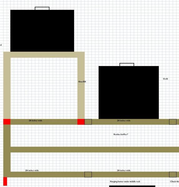
I want to keep it low because we were talking about making a modular 2'x2' square frame that could be mounted to the top of the frame with tabs (secured with bolts). This would allow us to either leave the HLT on the flat plane, or install the modular piece and raise the HLT (or any other pot) up high enough to do a gravity drain. i.e. we could batch sparge with one pump.
Thoughts? If I am being unclear maybe I can post a ghetto picture
CidahMastah
Well-Known Member
- Joined
- Nov 12, 2010
- Messages
- 4,201
- Reaction score
- 46
Here they are
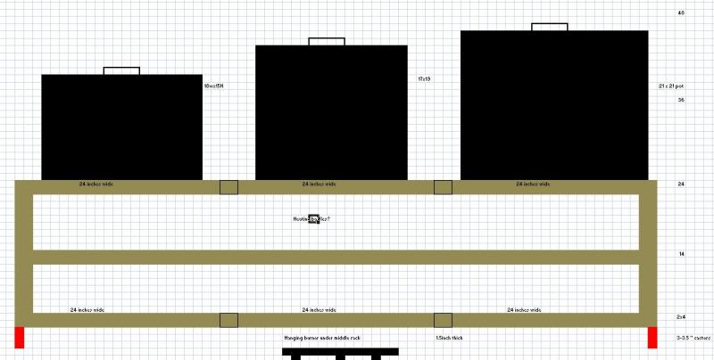
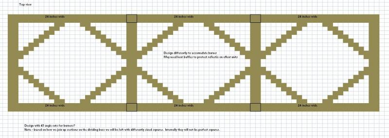
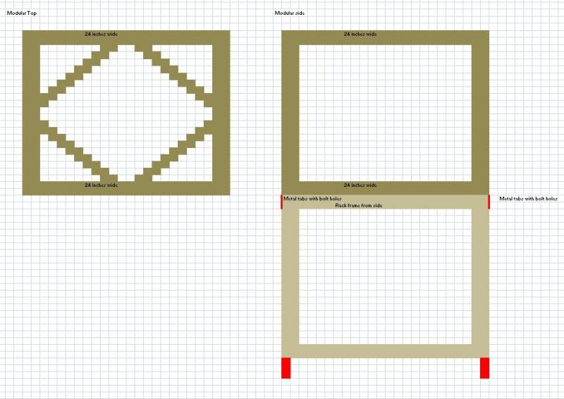


CidahMastah
Well-Known Member
- Joined
- Nov 12, 2010
- Messages
- 4,201
- Reaction score
- 46
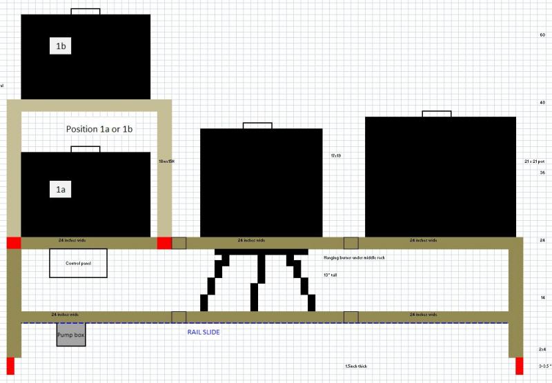
The frist beige horizontal line from the bottom on the first pic of the stand represents the height at 14'' and the second represents the height at 24''. The drawings are in squares that represent 1 square / 1 inch for pretty close scaling, though I actually have 1.5'' steel vs. the 2x2 scaling shown.
Red = welded metal plates that will have bolt on fastening.
While not shown the MT in the center will have a SP10 burner that will be hanging under it.
Red = welded metal plates that will have bolt on fastening.
While not shown the MT in the center will have a SP10 burner that will be hanging under it.
Let's see if I have this straight. You're going to do 3 cubes so it can be similar to a single level system, but then you're going to do an additional riser cube to be able to elevate the HLT?
I really don't know what the minimim amount of drop is to get good priming. At 24 inches on the smaller cubes, you shouldn't have a problem though. That is about the height I use for mine. I think one of the most important things is to keep your lines as vertical as possible so that the air easily moves out of the system. Longer lines that hang and have bends are going to trap air.
Another thought is that I would make the leg extensions a bit longer so you have room to mount the pumps under the bottom bar. Heat is a huge issue for the pumps on a gas system. If you mount your pumps under the bottom rung, they will be furthest from the burners and have no problems with the heat. Better yet is to put a shelf on the bottom rung to protect the pumps from heat and liquid.
CidahMastah
Well-Known Member
- Joined
- Nov 12, 2010
- Messages
- 4,201
- Reaction score
- 46
Let's see if I have this straight. You're going to do 3 cubes so it can be similar to a single level system, but then you're going to do an additional riser cube to be able to elevate the HLT?
No I should have been more clear. Going to do a single tier (1 big rectangle box), with one additional riser cube that can be bolted on any position (1st 2nd or 3rd) on the single tier. i.e. The first drawing as shown will not have a bar in the middle. The top will either be at 14 inches or 24 inches (not a bar at both as presently shown). If that still isn't clear let me know
I really don't know what the minimim amount of drop is to get good priming. At 24 inches on the smaller cubes, you shouldn't have a problem though. That is about the height I use for mine. I think one of the most important things is to keep your lines as vertical as possible so that the air easily moves out of the system. Longer lines that hang and have bends are going to trap air.
I plan on making a pump "box" that will mount to a slide rail (or just manually be movable). the box will shield the pump from liquids and the slide will allow it to slide to each position so it can be hooked up with camlocks directly under each pot (similar to the way yours is). Right now I have the one pump, if it stops making sense (time/$$ wise) to be creative I might just buy another pump.
Another thought is that I would make the leg extensions a bit longer so you have room to mount the pumps under the bottom bar. Heat is a huge issue for the pumps on a gas system. If you mount your pumps under the bottom rung, they will be furthest from the burners and have no problems with the heat. Better yet is to put a shelf on the bottom rung to protect the pumps from heat and liquid.
That is a great suggestion. There is no reason not to mount the pump (or rail slide) under the bottom and having the shelf would be great added storage.
I have two electric pots (HLT and BK), but the MT is direct fire for now. I like it that way in case I have an issue with an electric pot in the throws of a brew. I can always throw the boiling wort back into the MT and direct fire to finish the boil.
CidahMastah
Well-Known Member
- Joined
- Nov 12, 2010
- Messages
- 4,201
- Reaction score
- 46
So this is what it may look like at the end of the day. The bottom horizontal rail would be as low as it could be while providing clearance for the pump body under it, and plumbing.

CidahMastah
Well-Known Member
- Joined
- Nov 12, 2010
- Messages
- 4,201
- Reaction score
- 46
Finally got sick of waiting for my buddy and started cutting with the hope that we can get the welding done over the thanksgiving break. Had to stop with my cutoff wheel ground down too small. More to come (I hope this weekend)
You will see the rails where they were attached for the hand railing that we got the free steel from. I did a preliminary clean up to get the bulk of the metal off and will have to make some adjustment cuts. RIght now my brackets for the pots are 16'' pieces. I think I will be going with 15'' instead because I have to trim down the frame a bit so it fits overall dimensions of 6x 25.25'' (right now it is 6'x26'').
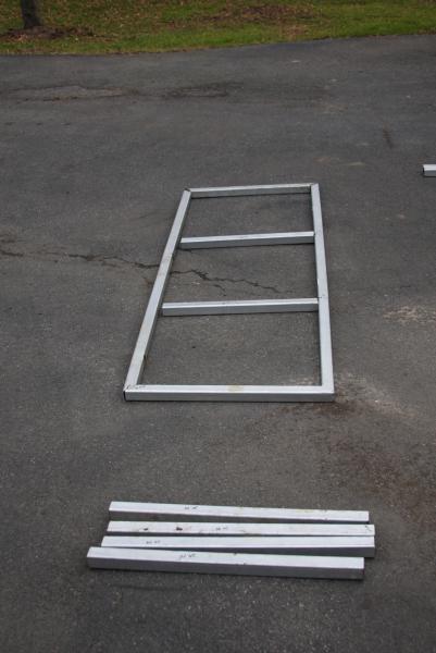
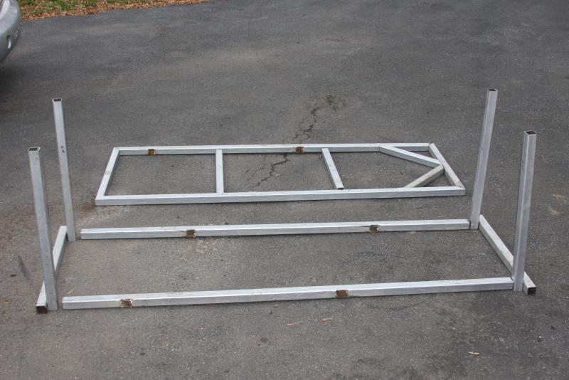

You will see the rails where they were attached for the hand railing that we got the free steel from. I did a preliminary clean up to get the bulk of the metal off and will have to make some adjustment cuts. RIght now my brackets for the pots are 16'' pieces. I think I will be going with 15'' instead because I have to trim down the frame a bit so it fits overall dimensions of 6x 25.25'' (right now it is 6'x26'').


Rondacker
Well-Known Member
Looking good!
CidahMastah
Well-Known Member
- Joined
- Nov 12, 2010
- Messages
- 4,201
- Reaction score
- 46
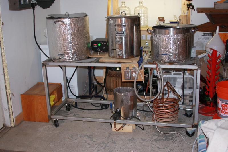
Been a while since I posted but finished the basic brew rig structure and have put 4 batches through on it to evaluate it and decide what changes need to be made. So for sure it would be convenient to add a pump!
Couple plans right off are to:
a. work on the tippy dump for the brew rig. If it makes sense we want to do this for the BK and the MT so they are easier to clean and rinse out.
b. Fasten the control panel to something where it is more protected (current plan is using a swing arm from an old desk).
c. more permanent pump attachment
d. Shelf on the bottom and a more organized electrical run of the wires.
d. Paint it in the spring!

Similar threads
- Replies
- 16
- Views
- 3K
Latest posts
-
Why didn't anyone ever tell me to buy a grain mill sooner
- Latest: corkybstewart
-
-
-
-
-
-
-

