Multiple GFCI wiring question

Homebrew Talk - Beer, Wine, Mead, & Cider Brewing Discussion Forum

Help Support Homebrew Talk - Beer, Wine, Mead, & Cider Brewing Discussion Forum:

This site may earn a commission from merchant affiliate links, including eBay, Amazon, and others.

Cpt_Kirks

Well-Known Member
Joined
Sep 11, 2008
Messages
3,704
Reaction score
60
Location
Lakeland TN
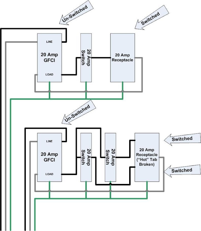
I use two 20A 120v circuits for my brewing. Currently, I have a 20A extension cord I made for each. Each cord has a 20A GFCI and 20A switch to control it.

Last weekend, I built a basic single tier wooden brewstand. Now, I'm thinking of taking my extension cords apart and building them into the stand.

One circuit I'm going to leave alone. It will be a 20A GFCI with a simple switch, same as I have now. That one will be for a heatstick only.

The other circuit I want to split. There will be a 20A GFCI with switch, and a 15A GFCI with switch. The 20A will be for a heatstick, the 15A will be for a pump. The 20A and 15A sub circuits will not be in use at the same time.

What will be the best way to wire the 15A and 20A GFCI's to the single input wire?

:confused:
 
Wire the 20amp GFCI to the line and run a separate receptacle from the "LOAD" terminals of the GFCI for the 15amp.

You do not need a 15amp GFCI, the 20amp will provide GFCI protection to anything wired from it's "LOAD" terminals.
 
Wire the 20amp GFCI to the line and run a separate receptacle from the "LOAD" terminals of the GFCI for the 15amp.

You do not need a 15amp GFCI, the 20amp will provide GFCI protection to anything wired from it's "LOAD" terminals.

Problem with that is, I need two switched circuits there. If I switch off the 20A GFCI, I turn off the heatstick and the pump.
 
You can put the switch after the plug in-line with your heatstick, or run 2 switched receptacles off the "LOAD" terminals (in which case you actually end up with three receptacles).
 
What I'm thinking, is to split the input.

Black will go through switches to GFCI units, white will connect to both GFCI units.

That should work, but GFCI's are a little odd at times.
 
What I'm thinking, is to split the input.

Black will go through switches to GFCI units, white will connect to both GFCI units.

That should work, but GFCI's are a little odd at times.

I think I understand what you want to accomplish and what you are talking about will provide power to the devices.

The reality is that you should try to have the GFCI as close to the source as possible for the most protection. Ideally a breaker or wall receptacle is the location of the GFCI. Every connection you have before the GFCI is NOT protected by it and every one after is. My thoughts were to try to get your gfci in your circuit as soon as possible.

So... wet hands, switches in front of the gfci... not the perfect setup.

This new setup is just a variation on what I'm using now:

IMAG0081.JPG


I see what you mean, but having the GFCI back in the circuit can have consequences, too.

A few years ago, I was working on some lights. The lights were plugged into a long extension cord, which was plugged into a GFCI. The lights shorted out against an aluminum table. The GFCI tripped, but because of the length of the extension cord, there was enough of a capacitive charge to give me a pretty good zap.
 
... A few years ago, I was working on some lights. The lights were plugged into a long extension cord, which was plugged into a GFCI. The lights shorted out against an aluminum table. The GFCI tripped, but because of the length of the extension cord, there was enough of a capacitive charge to give me a pretty good zap.
What? I don't think so.
There would not be any "capacitive charge" built up in an extension cord. More than likely, you were the path to ground that tripped the GFCI.
IMHO
 
Something like this could work:
The first 20 Amp GFCI "Load" is switched to an outlet. this gives you an un-switched outlet (The GFCI) and a switched outlet. This can be done inside a 3-Gang electrical box.

The second 20 Amp GFCI "Load" is run to each of 2 switches. Those 2 switches each feed 1/2 of another outlet. This way you again have an un-switched GFCI (Always on power, if you need it) and each plug in the receptacle is individually switched by breaking the "Tab" on the hot side of the 20 amp receptacle.

Essentially, you wind up with (2) unswitched GFCI protected receptacles, each on independent 20 amp circuits, and 3 switched 20 amp receptacles protected by the GFCIs.

All of this would fit in (1) 4-gang box, and (1) 3-gang box.

Switched%20GFCIs.jpg
 

Latest posts

Back
Top