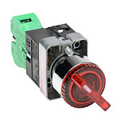
240v Switch Options

Homebrew Talk - Beer, Wine, Mead, & Cider Brewing Discussion Forum

Help Support Homebrew Talk - Beer, Wine, Mead, & Cider Brewing Discussion Forum:

This site may earn a commission from merchant affiliate links, including eBay, Amazon, and others.

illin8

Well-Known Member
Joined
Apr 1, 2008
Messages
468
Reaction score
5
Location
South County, RI
In planning out my control panel I initially decided I'd just do a DPST 30-amp switch to control both legs of power going to the SSR/heating element. In looking at the switches at automationdirect.com is there a better alternative? I really only need an ON/OFF switch to control power to the element.

Anyone care to share their experience and/or give me some advice? Are the automationdirect switches rated for 240v? What would I need? I'm inclined to just buy the damn $11 30-amp DPST switch from Home Depot and be done with it but I'm putting in an order with automation direct anyway...figured I'd ask before I put the order in.
 
Ive got the same question on this one. I was thinking of not breaking the leg on the 240V but instead breaking the leg on the low voltage coming into the ssr. That way i dont melt the switch together throwing that much power around, and low voltage switches are cheaper. Just got some of my parts for the rims, and about to start the build. It will be nice to get some info from people who have made one.
 
I think you better off using a relay to control the high voltage and letting the high voltage run through that, with low voltage at the switch.
 
This is what I am using. I am wiring power to one leg from the SSR and that will be my "auto" ON and the other ON will receive power right from the source and allow me to control my element manually
 
In general, it's best to have some method to positively disconnect both legs from the load. This is even more important when using an SSR, which can be susceptible to false turn-on, and can also fail in the closed mode.
 
Your method looks good, dose it work good manually switching that much power I will be switching 2 4500W heaters. I would normally be on auto, but want the capability to turn them off if i need to turn off a pump or something.
 
The DPST 30-amp switch I was planning on would cut both legs before the SSR. I was just wondering if something like
m_gcx1241120.jpg
would work (but I only see 120V, not 240v).
 
This switch is to be used in conjunction with contactor switches. Auberin has them.

When i step up to a dual element I intend to use this same switch with two contactors. The switch would be all off, BK element on, HLT element on. This switch only needs low power to run it. When the power is chosen the contactor closes the link on the line letting the power go through to the SSR and heating element. I am not sure why but I have heard a few suggest avoiding 240V going through a switch that is external. SSR and contactors allow a remote access to switching.

I had to do some research on contactors. They are pretty similar to SSRs but different in the following ways:

  • They are mechanical as opposed to solid state. Meaning they can wear out with lots of use like you would use an SSR. With these they should only be turned on once or twice a brew session.
  • They will fail open so not leave the power on.
  • They are cheaper and you can get 2 pole contactors for way less than DP contactors.

Here is Auberin's contactors.
http://www.auberins.com/index.php?main_page=product_info&cPath=2&products_id=164

BTW, I am using the HD 2 pole switch for my element now just on the output, downstream from the SSR. I had it in hand before I learned of this setup. I want to keep it simple for now but am running about 2 brew sessions per setup before I change things. Hopefully I can do my first 12 Gallon AG this weekend.

Does anyone know If I can do a 4 way switch off, BK-on, HLT-on, Both on?
 
It just so happens that I've been scouring this place for nearly two hours looking at control panel builds and trying to figure out what selector switches to use to control power for the PID's on my electric brew build. I've looked on ebay and have found these.

http://stores.ebay.com/chaudiolab-Multi-Store__W0QQ_sidZ287185144?_nkw=selector+switch&submit=Search

My big question is.... do I need a 12-24 volt transformer to run these? Hopefully this is not off topic and I'm not trying to hi-jack your thread. Like you, I need some advice on what to use.
 
The DPST 30-amp switch I was planning on would cut both legs before the SSR. I was just wondering if something like
m_gcx1241120.jpg
would work (but I only see 120V, not 240v).

Without sounding obvious, that's a control switch. It would typically be used to complete a circuit to the coil in a relay, contactor or motor starter. They are usually rated for pilot duty and low current direct switching, usually 3 amps max. 22mm and 30 mm panel switches like these look great, and can certainly be used to switch your typical homebrew rig circ pump, but in order to use them for heater elements you'll need a definite purpose contactor, which can be had pretty cheap.
 
Can someone explain how the switch and relay/contactor connect and work? Pics? I've looked around, thru control panel pics and such trying to figure out the wiring and connections but can't really tell. If I had them in my hand it would be a different story but not knowing what they look like makes it tough....
 
No photos and I have not actually wired one of these but here is my WAG (wild a$$ guess). You will have a neutral go directly to the contactor. There will be a "hot" wire going to the rotary switch. On a switch like this you will have NO or NC portions of it underneath these are separate parts of the underside of the switch you can add more of these NO or NC to the bottom to wire things differently as needed. NO stands for normally open or normally closed you choose which side you wire it to depending on how you want it to operate.

Normally open means the switch will be off no power going trough it. Wire it to the NO side of each switch so that it will close the circuit when switched in one position or the other. So with two NO switches underneath and wired properly the you will have one hot wire into the underside of the switch and two wires coming out of a NO side going to different contactors. In one position the hot wire will terminate at the switch meaning all off, no power downstream. In the other positions it will close the switch to allow power to go to one or the other contactor. The power from this contactor and the neutral on the other side of the contactor will energize the contactor which is just an electrical magnet. The magnet will "pull the switch over" closing the contactor and powering your 240 legs.

IHTMS (I hope that makes sense).
 
By the way, the "coil" voltage is the control voltage, so unless you have a 240v switch (I'm sure you would want the 120v switch, like the red one pictured above), you need the contactor with 120v coil.

For instance, use this contactor with this switch. You would run your 120v power to the switch, then to terminate at the contactor. Your 240v hot legs for your element goes through the contactor, then SSR (if used) then element. There is no neutral to use in the 240v power wiring. Hope that makes sense.
 
Budzu, that is exactly what I was looking for. Like I said without them in my hands to see them and how they connect I wouldn't know how to wire them. One question though, what do you mean when you say "then to terminate at the contactor"? Do you have to 'jump' the power from the switch to the contactor (I doubt that)?
 
Budzu, that is exactly what I was looking for. Like I said without them in my hands to see them and how they connect I wouldn't know how to wire them. One question though, what do you mean when you say "then to terminate at the contactor"? Do you have to 'jump' the power from the switch to the contactor (I doubt that)?

By that I mean that is where the 120v power ends. The switch has input and output hot connections, and the output goes to the contactor, and that's it. You'll also hook your neutral up to the contactor from your original 120v power source.

edit: Also I'm pretty sure the LED of the switch needs its own power, that will involve positive AND neutral 120v connection. Not sure though as I do not use those models. Lots do though, surely someone can help you with that part.
 

Latest posts

Back
Top