You are using an out of date browser. It may not display this or other websites correctly.
You should upgrade or use an alternative browser.
You should upgrade or use an alternative browser.
Cake pan + skateboard wheel + bike brakes = homemade peristaltic pump??
- Thread starter TheFlyingBeer
- Start date

Help Support Homebrew Talk - Beer, Wine, Mead, & Cider Brewing Discussion Forum:
This site may earn a commission from merchant affiliate
links, including eBay, Amazon, and others.
OP
OP
TheFlyingBeer
Well-Known Member
As a suggestion I would try to add a short length of the same diameter tubing as a buffer between the two exits. This should make the pump operate smoother and last longer with less vibration as the rollers will be evenly engaged at all times.
I was tossing that idea around before but I think it might be hard to actually make and I don't know if it will really be needed... time will tell I guess. Cutting the tube to the correct length and finding a way to secure it to the pump wall are the biggest obstacles.
Still waiting on the shaft coupler to give this motor a proper test but in the meantime I have kept myself busy.
Built the mount for the motor/pump:
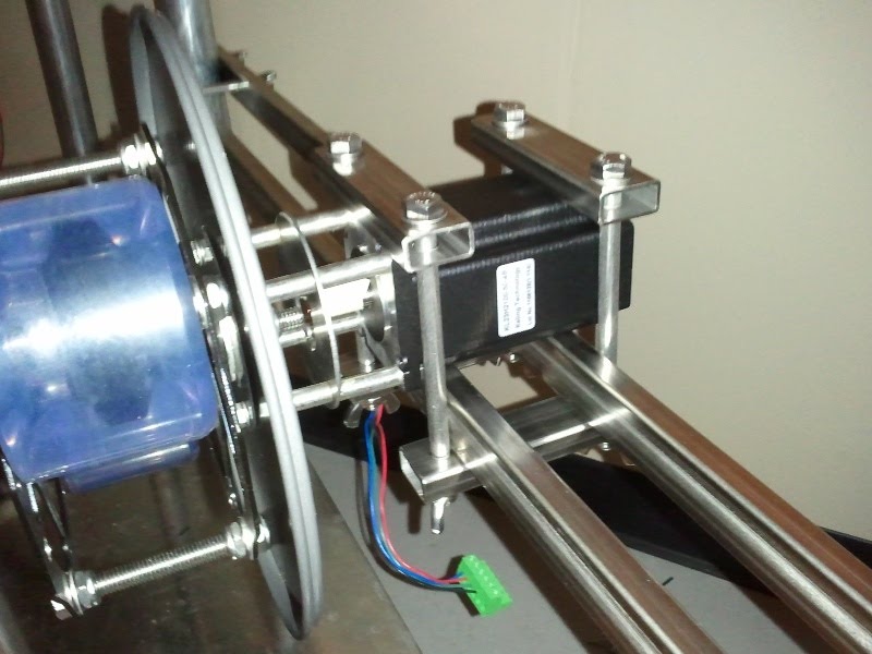
I will see if some rubber strips are needed to isolate vibrations from the work table once it is all up and running. Even with the bolts just hand tight the motor is firmly in place so I think it might work.
Mostly finished the microcontroller code last night for the pump's "manual/hand" mode. Based on a potentiometer (to be mounted on my control panel) the motor will move at one of 10 speeds in forward or reverse. I only have acceleration/deceleration left which is not critical right now as the speed can just be slowly stepped up to the desired speed manually.
SpacemanSpiff
Well-Known Member
Very cool design! As someone who's used peristaltic pumps here and there for work, this---
will be very important. Can't tell you how many times that tubing goes at the worst possible moment.
At some point once I finish getting an actual motor connected to this I want to test the longevity of the tubing so I can make plans to replace it on a regular schedule rather than have a failure in the middle of a brew.
will be very important. Can't tell you how many times that tubing goes at the worst possible moment.
OP
OP
TheFlyingBeer
Well-Known Member
Coupler came in yesterday so I finally had a chance to put the stepper motor to the real test. Unfortunately the results were a mixed bag. With a bunch of tweaking I can now rather reliably achieve 100RPM with no skipping of steps. I had to finely adjust the rollers to maintain a balance between suction and motor torque.
The part of the pump where no tubing was being compressed caused issues with the motor and it would often stall. As discussed just a bit earlier in the thread with MaxOut I created a way to even out the motor load for the entire rotation. Instead of adding an additional piece of tubing I used adhesive backed rubber strips and some 3M 2242 rubber electrical tape to build up something for the rollers to press against. With the 2242 the thickness of the "false tubing" could be changed in small amounts until it was just right.
The 570oz-in rated torque of the motor is on the borderline of acceptable. Although 100RPM is sufficient I would like to have some extra torque overhead to prevent stalls or skipped steps if any issues come up. For the second pump I will be buying a higher rated motor and if I ever find a different need for this motor it will also be replaced with a stronger one.
Finally, the tubing slipped out the front/top of the pump once in my many trials. Once is enough to indicate I need to do something about the design as I don't intend to monitor the pump 100% of the time during brewing. I have seen other pump heads that use another set of rollers to keep the tubing in place and I plan to create something along the same lines:

So, although there were some issues I feel that this idea might actually pan out! Once I do some additional tweaking and build up the proper power cables for the motor and driver I will create another video and post it.
The part of the pump where no tubing was being compressed caused issues with the motor and it would often stall. As discussed just a bit earlier in the thread with MaxOut I created a way to even out the motor load for the entire rotation. Instead of adding an additional piece of tubing I used adhesive backed rubber strips and some 3M 2242 rubber electrical tape to build up something for the rollers to press against. With the 2242 the thickness of the "false tubing" could be changed in small amounts until it was just right.
The 570oz-in rated torque of the motor is on the borderline of acceptable. Although 100RPM is sufficient I would like to have some extra torque overhead to prevent stalls or skipped steps if any issues come up. For the second pump I will be buying a higher rated motor and if I ever find a different need for this motor it will also be replaced with a stronger one.
Finally, the tubing slipped out the front/top of the pump once in my many trials. Once is enough to indicate I need to do something about the design as I don't intend to monitor the pump 100% of the time during brewing. I have seen other pump heads that use another set of rollers to keep the tubing in place and I plan to create something along the same lines:
So, although there were some issues I feel that this idea might actually pan out! Once I do some additional tweaking and build up the proper power cables for the motor and driver I will create another video and post it.
deerelk4x4
Member
The issue I am having with the 360° design is the spiral in the tubing causes it to slowly creep up the wall of the pump head and eventually it moves clear of the roller causing the pumping to fail. In this design I added a second wheel (still have 2 to spare) and the tubing now sits on a flat plane rather than a spiral. The second wheel was needed to maintain occlusion since the tubing only covers 250° of the circumference now.
tubing creep up the wall in an inherent problem with these kinds of pumps. Most commercial pumps that I have seem always have two sides to them to prevent the tubing from leaving the pump.
Something to consider would be to put a small space in the back and again on a cover pan to ensure the tubing won't creep out from under the roller.
I really like your design and have used these types of pumps at work for various types of liquid movement. Hadn't thought of using it my brewing setup and might build one instead of buying a march pump.
DrewBrewTheGreat
Well-Known Member
Really cool. Like the adjustable set up too.
"I have seen other pump heads that use another set of rollers to keep the tubing in place and I plan to create something along the same lines:"
Could you use another skate board wheel with a groove that is the size of the tubing to keep the the tubing in place? Use a router to cut the grove?
"I have seen other pump heads that use another set of rollers to keep the tubing in place and I plan to create something along the same lines:"
Could you use another skate board wheel with a groove that is the size of the tubing to keep the the tubing in place? Use a router to cut the grove?
terror_storm
Member
Coupler came in yesterday so I finally had a chance to put the stepper motor to the real test. Unfortunately the results were a mixed bag.
I think this would be the perfect application for an automotive power window motor. Should be about the right rpm, gear reduction with plenty of torque, reliable, and cheap.
thunderchief
New Member
This is a really intriguing pump head that you have pieced together. I am a little bit confused with how you arranged the bearing(s) at the penetration of the shaft through the cake pan. I can see using a bearing on each side of the pan and then tightening locknuts on the threaded shaft to hold them in place, but I was unable to think of a good way to ensure that the shaft will start centered and remain that way. Could you elaborate a bit on this detail?
thunderchief
thunderchief
OP
OP
TheFlyingBeer
Well-Known Member
There is a ring of Gorilla super glue around the base of each bearing that secures them in place. I was planning to eventually JB weld them if the glue didn't hold up but it hasn't been an issue yet.
My work on the pump has been put on hold for a little while as I piece together the remaining items of my brewery. I am confident enough that the design should work so I am now focusing on getting everything else in order.
My work on the pump has been put on hold for a little while as I piece together the remaining items of my brewery. I am confident enough that the design should work so I am now focusing on getting everything else in order.
OP
OP
TheFlyingBeer
Well-Known Member
Any progress on the pump?
Well, Santa was generous so I have purchased the components to build a second pump head. I also just bought two 906oz-in steppers to run the pumps. Should be a real improvement over the 570oz-in motor I tried the pump out with. In about a month I should hopefully both up and running.
rockinmarty
Big Member
subscribed. Can't wait to see the final product
OP
OP
TheFlyingBeer
Well-Known Member
subscribed. Can't wait to see the final product
Your lucky day I guess. I received one of the final pieces today on a slow boat from China -- the larger shaft couplings needed for the new motors. Here is a shot of what the larger motor and new mounting bracket look like. I used as much of the old mount as possible.
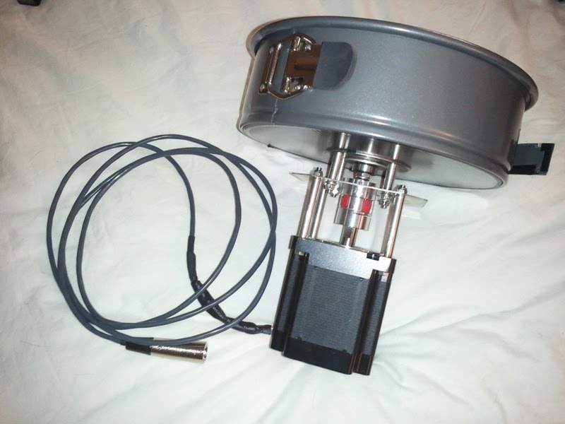
The power cable is terminated with a 4 pole XLR connector to mate to my control panel. The plate between the standoffs on the mount was a piece of waste SS cut from my brewery table top.
Another item I finished today after a trip to Home Depot is the device that will keep the tube inside the pump head AKA the "tube minder". It is built very similar to what I showed in a model previously except I reversed the orientation of the screw for easy assembly:
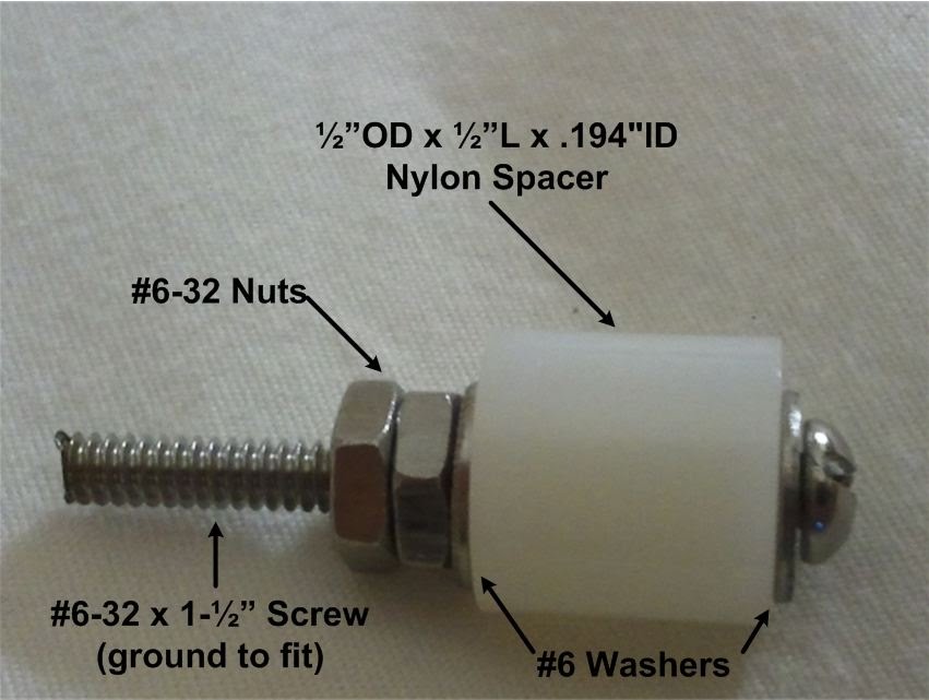
There will be two on each pump mounted opposite the skateboard wheels:


The #6-32 screws into a tapped 5/16" nut:

This arrangement works well as the tighter the #6-32 screw is torqued the better the nut stays in one place. Works like a set screw.
I hope I can get a trial run completed by Friday so I can put a few longer duration runs on it this weekend. More updates to follow of course

TriangleIL
Well-Known Member
Subscribed. This is one of the most badass things i've seen on HBT.
OP
OP
TheFlyingBeer
Well-Known Member
Subscribed. This is one of the most badass things i've seen on HBT.
Man, the pressure is on. Thanks all!Subscribed. This is so full of win.
Really nice build, can't wait to see results of long term trial.
If I understand, the nylon spacer will rotate between the washers? Do you think that will cause much wear with the nylon rubbing on the threads?
Just an idea, but I got a deal a long while back on a bunch of roller blade bearings and have used them in a ton of projects. A few of those stacked as a roller might work well.
Just an idea, but I got a deal a long while back on a bunch of roller blade bearings and have used them in a ton of projects. A few of those stacked as a roller might work well.
OP
OP
TheFlyingBeer
Well-Known Member
lschiavo said:If I understand, the nylon spacer will rotate between the washers? Do you think that will cause much wear with the nylon rubbing on the threads?
Just an idea, but I got a deal a long while back on a bunch of roller blade bearings and have used them in a ton of projects. A few of those stacked as a roller might work well.
Correct, the washers aren't tightened down so the nylon standoffs can rotate freely. I hope there won't be enough pressure to wear the nylon out. A few post ago I showed a 3D model that uses bearings instead of the standoffs. The spacers were less than $0.50 so I thought I would give em a shot before buying the bearings online. Thanks for the input!
Correct, the washers aren't tightened down so the nylon standoffs can rotate freely. I hope there won't be enough pressure to wear the nylon out. A few post ago I showed a 3D model that uses bearings instead of the standoffs. The spacers were less than $0.50 so I thought I would give em a shot before buying the bearings online. Thanks for the input!
Sorry, totally missed that. Nice looking project
OP
OP
TheFlyingBeer
Well-Known Member
Just in time for some weekend tinkering I managed to get my control panel wired up enough to give this new revision a test run. From the cardboard in the picture you will clearly see the microcontroller circuit has a lot of work left.

I created a short video (sorry for the poor lighting) with the sides of the cake pan removed so it is easier to see. The pump is being run at a constant speed to check for any missed steps or issues.
[ame="http://www.youtube.com/watch?v=Quqh-aG4Uho"][YOUTUBE]Quqh-aG4Uho[/YOUTUBE][/ame]
I think I will offload the step creation from my main microcontroller to a small micro that has only one function. For brewery operations the main microcontroller will have too much going on that the steps might get jumpy from time to time. I can't use the dedicated PWM hardware of my controller as it is already purposed for my PID controlled heating elements and the motor will operate at varying frequencies. The PWM hardware only supports one frequency for all channels at any given time.
Foosinho
Well-Known Member
Looked like a production model to me.From the cardboard in the picture you will clearly see the microcontroller circuit has a lot of work left.
OP
OP
TheFlyingBeer
Well-Known Member
Looked like a production model to me.
Maybe I should clarify, the actual microcontroller is a LPC1768 that is populated on a LPCXpresso development board. The LPCXpresso itself provides all of the support circuits to get the microcontroller working but doesn't provide much for external peripherals. I will be creating a motherboard that will expand all of the signals and functions I need. The small white breadboards on each side of the blue main board breakout some of those signals.
Foosinho
Well-Known Member
No need - I'm an EE, and it was a joke.Maybe I should clarify
")
I feel like a bit of an outsider, I'm not EE. But I did stay @ a Holiday Inn Express last night.
TFB I really liked the video of the test, thanks for posting. It seem in the video that the motor is rather loud. What is your opinion? I only have experience with the march/chugger pumps.
TFB I really liked the video of the test, thanks for posting. It seem in the video that the motor is rather loud. What is your opinion? I only have experience with the march/chugger pumps.
gunner65
Well-Known Member
lschiavo said:I'm an EE nerd, I got it
I prefer geek when talking of my obsessions. So I am a EE geek.
wfahey
Well-Known Member
Maybe I should clarify,
Yup, and the flux capacitor provides the Gigawatts necessary to move a Delorean through time. Ok, you left me in the dust with that explanation but I am loving this thread so I will try to keep up.
TaylorInOK
Well-Known Member
This goes up there with "I think i'll make my own touchscreen today."
Great job! Subscribed!
Great job! Subscribed!
Djlunchbox
Well-Known Member
subscribed for awesomeness
OP
OP
TheFlyingBeer
Well-Known Member
I will blame the farmhouse IPA or RIS I had last night on missing the joke here.
Luckily I found a touchscreen for cheap on eBay.... didn't have to build one of those
I am not familiar with the loudness of march/chugger pumps but I can say that this larger motor sounds much better than the smaller one I previously tried out. When I was putting the video together I thought it sounded worse when recorded than in person. Also, it is sitting on my computer case which was kind of resonating the sound as well. I guess the true test will be when it is actually pumping and secured to its mount on my brew table.
This goes up there with "I think i'll make my own touchscreen today."
Luckily I found a touchscreen for cheap on eBay.... didn't have to build one of those
I feel like a bit of an outsider, I'm not EE. But I did stay @ a Holiday Inn Express last night.
TFB I really liked the video of the test, thanks for posting. It seem in the video that the motor is rather loud. What is your opinion? I only have experience with the march/chugger pumps.
I am not familiar with the loudness of march/chugger pumps but I can say that this larger motor sounds much better than the smaller one I previously tried out. When I was putting the video together I thought it sounded worse when recorded than in person. Also, it is sitting on my computer case which was kind of resonating the sound as well. I guess the true test will be when it is actually pumping and secured to its mount on my brew table.
Scut_Monkey
Well-Known Member
Let me know when you start selling these and can you give me a shipping quote to 15229?
OP
OP
TheFlyingBeer
Well-Known Member
Anything new to report?
Sorry, not much new stuff on the pumps. I wired up the new motor, performed a quick test, and then moved onto the next components of the brewery that needed to be worked on.
The central control board was next in line:
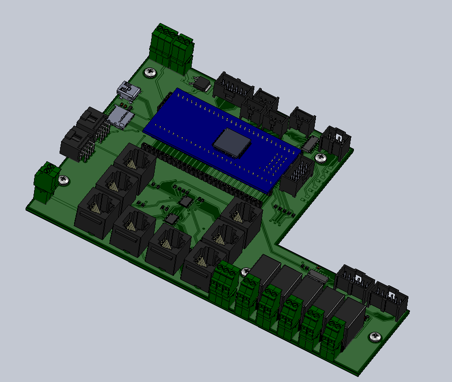
Just putting the finishing touches on the layout and then I will send the PCB files out to be created. This control board has a dedicated PIC18F25K22 (hidden under the blue LPCXpresso board) to perform the stepper motor control. The standalone controller should allow for more accurate timing and no missed steps. The LPCXpresso board can only allow a single frequency for the PWM output where the PIC18 can provide individual frequencies per channel.
That's not even a real picture. I think you're just making things up.
klyph
Well-Known Member
That's not even a real picture. I think you're just making things up.
Yeah, why are you playing with legos?
Sorry, not much new stuff on the pumps. I wired up the new motor, performed a quick test, and then moved onto the next components of the brewery that needed to be worked on.
Just putting the finishing touches on the layout and then I will send the PCB files out to be created. This control board has a dedicated PIC18F25K22 (hidden under the blue LPCXpresso board) to perform the stepper motor control. The standalone controller should allow for more accurate timing and no missed steps. The LPCXpresso board can only allow a single frequency for the PWM output where the PIC18 can provide individual frequencies per channel.
I've been really interested in this from the beginning. I want to give this a shot. I was just thinking of using a gear drive motor though, which means I guess I won't have much flow control. I'm assuming that you can not restrict your output flow because you could (or would) pop the silicone tubing.
Similar threads
- Replies
- 4
- Views
- 724
- Replies
- 25
- Views
- 4K
- Replies
- 6
- Views
- 3K
