New eBIAB build, questions about controls

Homebrew Talk - Beer, Wine, Mead, & Cider Brewing Discussion Forum

Help Support Homebrew Talk - Beer, Wine, Mead, & Cider Brewing Discussion Forum:

This site may earn a commission from merchant affiliate links, including eBay, Amazon, and others.
Switchable 120/240 is something I really wish I had in my eBIAB, but I'm not sure I see the value in the vssr. I understand the desire to have power control, but in my experience, you just don't need that level of tuning.

I recirculate my mash in my cold garage with the 240v element at 3-5% on the manual pid, it holds perfectly. (+\- .5) At boil I jump it up to 100% until hot break, and then back down to 55 for the boil.

If I had the 120 option I could get more consistent heat during the mash by having more on time without overheating, plus it would reduce or eliminate the scorch risk, even with a heavy mash on the element. It would probably also mean I could let the pid maintain mash instead of manual. I'm just not seeing where I would want to have some power level between 5500 and 1375.
 
OK, now I have my head wrapped around it. I was originally thinking of an SSR in the terms of a very fast mechanical relay, and the dspr1 being independent of the source power being switched, but that's not the case.

Not a huge deal, as thankfully I have the switch and the drawing is easy to change.

The whole idea about controlling the element power is to prevent any sort of scorching while doing a temperature controlled recirculating mash. Is it really an issue that needs to be worried about? The element is a 5500 Watt ripple element, 60 watts per inch ULWD.

Bearded, how come you don't use the PID mode when mashing? Have you had a scorching issue? I would tend to think that the PID would use the same power to the element to maintain temps as you are currently.

Doug, in your diagram for the switchable control between the PID and the DSPR1, you show a 3 position switch with 4 NO contacts. Any reason it can't be a two position switch? I was thinking about using the SW16 with two sets of NO/NC contacts, and using the light in the switch as an element power on indicator.

Probably best to switch through open, hence the 3 position switch. And for your element on light, you want a 240v light wired in parallel with the element. Have fun. :)
 
Jeff,

I have an element firing light, and it is a 240v light that will be in parallel with the element.

I was thinking more in line with using the light on the PID/DSPR1 control selector switch to indicate that the contactor is indeed switched on and has power flowing through it. In the diagram, it would be the 'Element power on' light.

The switch will only be carrying the SSR control signal, no high power. I would think a DPDT switch would be fine; that's all they show in the DSPR1 manual using this configuration.
 
Bearded, how come you don't use the PID mode when mashing? Have you had a scorching issue? I would tend to think that the PID would use the same power to the element to maintain temps as you are currently.

In theory the PID would be the best way to maintain the mash for sure. In practice it takes some time / effort to properly tune the PID, even with the auto-tuning models. The best tuning would be done during a mash, but I haven't had the time/grain to go through that exercise.

My current tuning for strike water likes to over-shoot by 3-5° and then settle back down very slowly. Adding grain to the equation slows the response down even more, so there is more overshoot. Rather than mess with it, I've just been using manual mode. I am certain that if I went in and manually tweaked the P/I/D settings, and then possibly let it re-run an auto tune, that it would settle in comfortably for me.

The only time I've seen signs of scorching on my 5500w straight fold-back element was when I played around with a 30% manual to do a mash-out. I do not detect any hint of toast or burn in the finished beer, and there was no damage or staining on my bag, but a 1-2" section of the normal beige sludge on the element had blackened by the time I drained the kettle and started cleanup. Your ripple element should be significantly less likely to scorch.
 
Where do you have your temp sensor, out of curiosity? I'm fairly sure I'm sticking it in the kettle outlet, as the only time I'll be concerned about temps is when I'm recirculating. My theory is if I keep the wort that was just circulating past the element at the correct temps, I won't prematurely denature the enzymes. And if everything else works right, I'll be circulating quick enough that temperature stratification shouldn't be an issue.
 
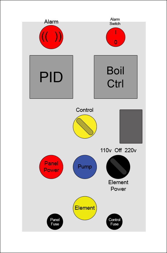
In light of the recent discussion about using two SSRs in series being an issue, here's the new theoretical panel with the capability of powering the element with either 110v or 220v, based on Doug's schematic in post #31 of this thread.

Only needed to order the SW16 and the additional set of contacts for it. Hopefully, I'll be at the actually assembling things stage soon, instead of the 'make plans and keep second-guessing' stage I'm currently at. :)

On a related note: The SSR will have one hell of a huge heat sink, I ordered a scratch and dent enclosure with a dual SSR heat sink that mounts on top. With only one SSR, heat dissipation shouldn't be an issue. Also, I'll now have an extra SSR.

Panel-Layout-110-220.jpg
 
Last edited:
Where do you have your temp sensor, out of curiosity?

I went cheap on my kettle, so my stubby PT-100 is just wing-nutted through the kettle wall, low in the kettle, across from the pick-up tube. This is not ideal from a control standpoint, but what I have found is that if I keep my circulation rate high, there is very little difference between what is read on that probe and what I measure when I stick a thermometer into the return wort stream.

I still think I want to move the location of the sensor to somewhere in the plumbing, but on some level it shouldn't matter. If the pumping rate is high, and the insulation on the vessel is good, then the temperature everywhere should be the same.
 
...
Doug, in your diagram for the switchable control between the PID and the DSPR1, you show a 3 position switch with 4 NO contacts. Any reason it can't be a two position switch? I was thinking about using the SW16 with two sets of NO/NC contacts, and using the light in the switch as an element power on indicator.

The two position switch should work, as long as the switch operates in the "break before make" mode for the NO/NC pairs. Most switches are designed to work this way.

I wouldn't use the same scheme to switch between 120V/240V as the center off position is needed to positively kill power to the element, and the time required to switch thru the off position gives the on contactor time to drop before the off contactor picks (break before make.)

I like the idea of using the LED in the SW16 to indicate power is enabled to the elements.

Brew on :mug:
 
The 120/240 switch is a 3 position center off switch, for the exact reasons you mention.

Looks like I have a final design, now to nut up and start cutting. *gulp*
 
Some of you guys are a lot smarter than I am. I got a C in my first industrial controls class and was 16 credits short of a EE so help me better understand the problem with inline SSRs please.

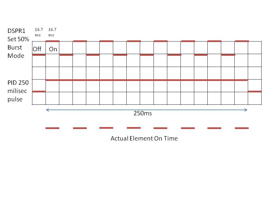
I get the extra heat dissipation argument just fine. It just seems odd to select between full power and quarter power via voltage switch when the DSPR1 is an infinite voltage selector (in practice).

Does this not work as I think it does?

DSPR1_PID.jpg
 
Too late for a panel layout suggestion?

This option adds one more indicator light, but the symmetry seemed nice.

Panel-Layout-110-220.jpg
 
Too late for a panel layout suggestion?

This option adds one more indicator light, but the symmetry seemed nice.

Separate lights for 120V and 240V operation would require that the lights be put in parallel with the contactor coils rather across the contactor outputs. Personally, I would rather have the light follow the actual contactor output than the contactor input (direct indication rather than indirect indication.) Having the light on the output also lets you make sure that the contactor that was on has dropped when switching between voltages (light will go out), to help you from switching too fast.

Brew on :mug:
 
Bobby:
Heat dissipation isn't an issue; I've got heatsink to spare, as I ordered a dual SSR heatsink (rated for 60 amps worth of SSR).

I didn't mean for this to turn into a pissing match, I just want to make sure I do this the right way the first time.

I popped the SSR in series question to Auber's tech support E-mail, I guess I'll see what comes back from them.


And... It looks like I'm back to the 'make plans and keep second-guessing' stage. :confused:
 
I think that in practice it may work just fine. Particularly as you would likely be using either the PID or the boil control, and set whichever you aren't using to 100% output.

The problem may come if you have a very low duty cycle from one or the other SSR controller. They are both syncing their ON pulses to the mains frequency, but the SSRs are going to lag behind the control input.

So if the first SSR is delayed by 1/2 a cycle, the second SSR will not turn on until the next zero crossing. At least if my memory serves correctly, the SSR needs to see the voltage coming down to zero in order to turn on, it won't just turn on with no voltage across the load terminals.

So if your first PID is running a 50% duty cycle, and the second boil control is also running a low duty cycle then you may have issues with the actual SSR being in coordination. The boil control and PID will be in sync as they both reference mains frequency but it doesn't necessarily follow that the SSRs will sync up

This is theoretical though, in actual use scenarios you may never see this happen.
 
Ok, here's a hypothetical question in regards to the timing of the SSRs:

They're both getting the signals from the power being switched, right? So when the first SSR lights up, they're more or less both in sync nearly instantaneously, as they're both seeing the same sine wave from the power. I'm also wondering if the 'leakage' past the SSR would be enough to serve the purpose of a 'carrier wave' of sorts.

Of course, I don't know jack-all about any of this aside from knowing my way around a schematic and a solid knowledge of how to wire up components. I'm shooting in the dark, so to speak.
 
Not quite. The SSR switches on at a zero crossing. It takes time to know that it has to switch on, so if the input is fired at one zero crossing, you have to wait 120th/sec before it can switch on. So you are likely losing half a cycle on the first SSR. Then the second SSR has to go through the same thing after the first SSR has turned on.

I don't know that you'll get enough leakage current through the first SSR, and IIRC an SSR needs a certain amount of voltage across the load terminals to work correctly.

The PID and boil control don't actually know if the SSRs have successfully turned on, they can only regulate their own output and assume that it is 100% effective.

Like I said though this should really be academic in practice, you will be using either the PID for mash control when you would set the boil control to 100%, or have the PID set to say 250F or 100% manual power and use the boil control for boiling. So in actual use there should be no conflict.

If you wanted to dial down the element power when mashing using the boil control, you may be just fine, as the PID will ramp up its duty cycle in response to the temperature drop if you are losing more power than expected from the boil control competing with the PID.
 
Ok, so finally heard back from Auber on their forums. The two SSR in series will work, they'll just make a bit more heat. That's no issue as I have a dual SSR heat sink mounted to the top of my control panel that's rated for 60 amps, anyway.

They also mention the switching control configuration.

Sooner or later I have to make up my mind. The sticking point for me is I'm still not entirely sure if I even *need* to control power to the element, as I'm not sure how much of a scorching issue there really is during mash recirculation/ramping temps (Multi-step mash, ramping up to mashout).

Also, since Uncle Sam owes me more than I expected, I'm in the process of ordering a stainless basket to mash/recirculate in.

You plan will work, but you don't have to use two SSRs. When you have two SSRs in series, the heat generated by the SSRs are doubled. You can just use one SSR to drive your heating element, connect both the PID and the DSPR1's control signal to the SSR, and then use a switch to select which unit will bed connected to the SSR. You can check the wiring example 2 in page 2 of the manual of DSPR1. Or you can keep both negative wires from PID and DSPR1 connected to the SSR's pin 4, and only switch the positive wires. In addition, I would suggest you add a mechanical contactor before the hot line goes to the SSR so you can cut off the power when needed.
 
The sticking point for me is I'm still not entirely sure if I even *need* to control power to the element, as I'm not sure how much of a scorching issue there really is during mash recirculation/ramping temps (Multi-step mash, ramping up to mashout).

Also, since Uncle Sam owes me more than I expected, I'm in the process of ordering a stainless basket to mash/recirculate in.

I can tell you that I believe my scorching was due to the insulating effect of the grain and bag resting directly on the element. It was compounded by the fact that I regularly stir inside the bag, kicking all of the grain dust out of the mash filter and back onto the element. Since that incident I have dialed back my maximum (bag-in-contact) power to 15% on the manual PID (pulsing full 5500W power 15% of the time) and have seen no evidence of scorch, even with the bag on the element and stirring.

If you are ordering a basket, I have a hard time believing scorch would ever be an issue. I would think a simple grill or grate over the element might do the same thing.
 
Ok, thanks for that bit of info. One way or another, I was planning on keeping the bag off the element. With the stainless basket that's a given.
 
Well, today was 'nut up and start making holes' day.

Thankfully, I was able to borrow a punch set for the round holes. Made a lot of it much easier, especially the holes for the plugs at the bottom of the box.

panel-1.jpg
 
That looks great. It always takes some steeling of nerve before you still that first hole in the box. Punches are wonderful too aren't they? Such a civilised way to make perfectly round holes
 
Thanks!

Yes, Punches are great. Now if only the set I had contained the right sizes for the L14-30 and the L6-30 receptacles... One size hole saw I have, now I'm off to buy the one I don't have. Nuts.
 
Looks good! What were the final decisions on operating modes:
  • Switchable 120V/240V or 240V only?
  • Switch control signals to a single SSR or two SSR's in series?

Brew on :mug:
 
No, decided to go 240 only. Single SSR, the yellow switch selects what's controlling the SSR. Figured I'd do it the easy way first, see how it works out. If I have any issues, it won't take much to change to a dual SSR configuration.

Right now the plan is when the contactor powers up the element, the yellow selector switch will light up, signifying the controls are active. The pushbutton switch light will indicate when the element is firing. Eliminates an extra hole in the panel.
 
Well, crap. I may be at a standstill.

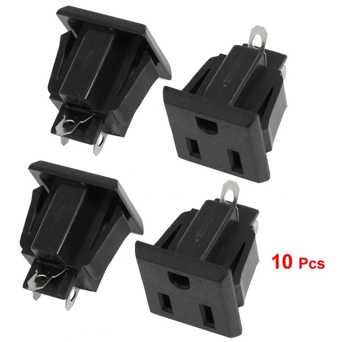
My original idea for the pump outlet was to use this:
61qEOlC0TuL._SL1100_.jpg


Now, I'm not so sure. Two issues: They require a small square hole (argh!) and I'm wondering if I should just go with a twist-lock for the pump to ensure the cord doesn't fall out.

Issue is, if I go with a twist lock I can't get one here until Monday some time. That means the panel fabrication is halted, as I'm not keen on mounting everything only to take it apart again to put in the receptacle.

Unsurprisingly, neither Lowes or Homedepot carries flanged receptacles.
 
You can get single outlets which mount in a round hole at Home Depot I believe. Not twist lock though.

Could you not use a lug mounting twist lock with a hole saw drilled hole for the outlet itself? Assuming that you have a suitably sized hole saw that is
 
I was looking at that option. Not crazy about it, though. They're not going to as stable and sealed up as the flanged version.

While I'm not doing an 'no expense spared' build on this, I'm trying to build it right (and safe) the first time. I could use a day away from the building and research, anyway.

At least, that's what I keep telling myself! :)

The parts are already on order, should show up Monday, when I'm at work for my 24 hour shift, so Tuesday I can get back on it.
 
Some more updates:

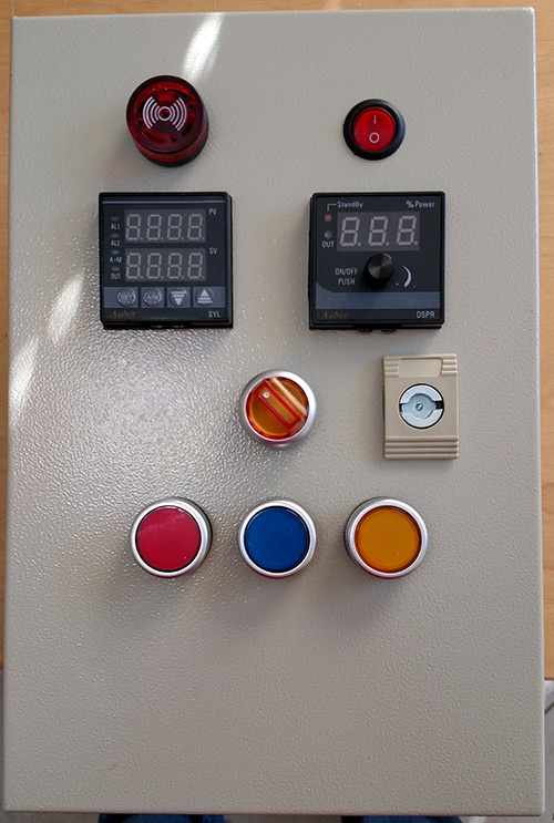
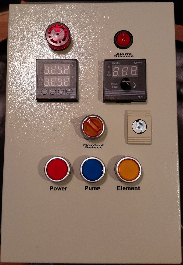
99% sure I'm done drilling holes. Everything's mocked up, so far it looks good. Decided to mount the fuses on the bottom, keep them away from the control panel face. It'll make it easier to route the wiring, as well.

Now on to mounting the internal components and wiring.

My 30A 220v GFCI breaker showed up after putting a nice $$ dent in my wallet, so all I need for the home wiring is the outlet/box.

Getting closer!

panel1.jpg


panel2.jpg
 
Everything's mocked up, so far it looks good.
What a great (clean) controller! At some point I am sure that I will rebuild my $6 harbor freight ammo box controller and will be looking at your design for ideas.

Keep us posted on the progress!
 
I'm in the process of laying out my panel and was wondering how far apart you spaced your buttons/ switches.
 
They're 22mm buttons, spaced 40mm apart if I recall correctly.
 
Good news, everyone! (Points if you read that in Farnsworth's voice)

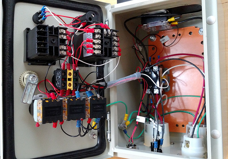
After hundreds of crimped wires that seemed as if they would never end and a lot of fussy work, the panel's done.

Bonus: When I powered up the 110v side of things, it all worked and no magic smoke leaked out! Granted the PID was in panic mode with no sensor and needing to be programmed, but it all worked and it even let me test the alarm buzzer (and the silence switch).

I still need to zip tie a few wires and neaten it up a bit, but it's functional. I also have the parts needed to install the outlet, and build the cord for the kettle. The power cord for the panel should show up in the mail tomorrow. It was actually cheaper to buy a ready-made cord than it would have been to buy the parts. My BIABasket should be here tomorrow, as well. Of course I'll be at work for my 24 hour shift tomorrow.

panel3.jpg


panel4.jpg
 
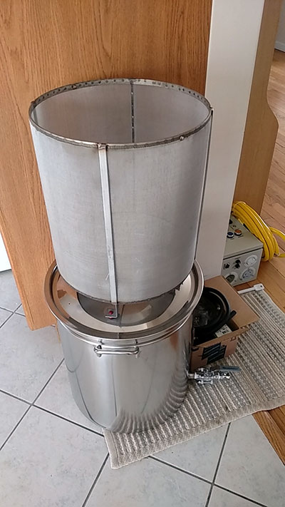
Basket and power cord came in! All I need to do is install the outlet, do a little re-arranging of my brew stand, and it's off to the races (or testing, as the case may be).

basket.jpg
 
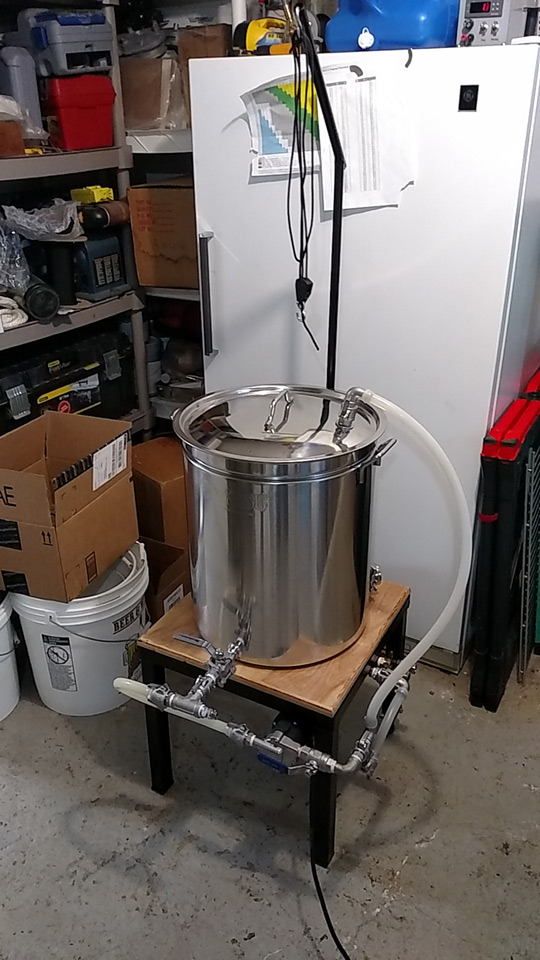
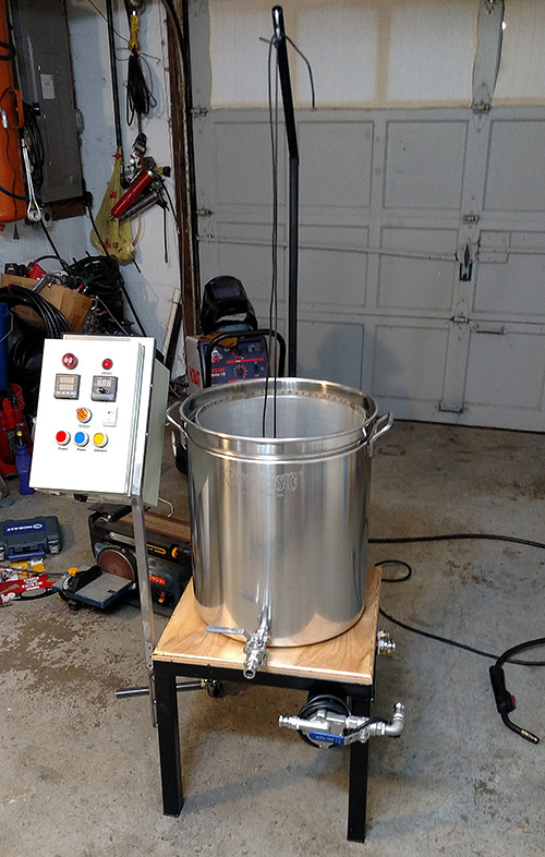
30A GFCI outlet installed, panel tested on 220v, kettle and chiller plumbing complete. Tomorrow I need to design and build the control panel mount, make a crossbar for the basket, finish the cord for the kettle element, and put the XLR connector on my RTD cable. Getting close to a wet test.

eBIAB-Stand1.jpg
 
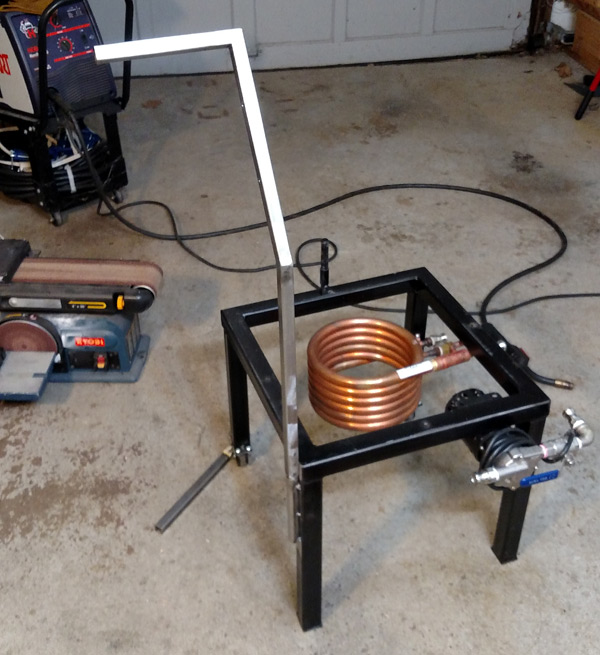
Control panel mount is done after a lot of planning, head scratching, cutting and welding. Also got the element all wired up. Done for the night, need to wait for the paint to dry.

bracket.jpg


mockup.jpg
 
Back
Top