Hello Gentlemen,
I've been lurking here for some time, planning on my eBrewery upgrade, I suppose it's time to leech a little more from this community.
I recently dropped a 4 pole 50A 220VAC into the garage in prep for the upcoming upgrade and I'm hoping to illicit the help of the very knowledgeable folks here, before I get started.
What I would like to achieve is a system that is capable of consecutive batches, but safe for clean up during boil. In otherwords, I want to be able to fire both elements at the same time. And be sure when they are not On so I can clean up.
I have an HLT HERMS, copper coil in the HTL, and a single pump with QD everywhere. I gravity to the BK, currently. The HLT and MT are both 15g keggle conversions. The BK is subject to change, but is currently just an 8 gal turkey fryer.
Here's what I'd like to do.
-Two elements 5500 and 4500.
-Auber PID for HLT control, with Alarm.
-Auber PID for BK control, with Alarm.
-I'll have a single pump, with room for an additional pump later.
-I would like to be able to switch off the power completely to either side of the rig, BK and HLT.
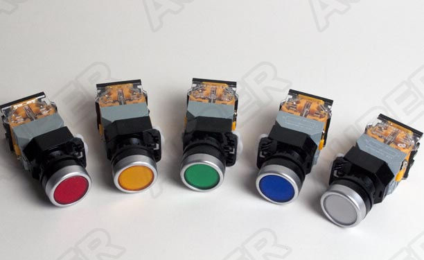
-I'd like an LED indicator that the power is on for each element and a separate indicator to show the element is active.
Please see my mark up design.

Any help with wiring diagrams and/or suggested components would be greatly welcome. (PJ?)
I will be documenting the build here.
Thanks to all.
---
It's Beer:30.
I've been lurking here for some time, planning on my eBrewery upgrade, I suppose it's time to leech a little more from this community.
I recently dropped a 4 pole 50A 220VAC into the garage in prep for the upcoming upgrade and I'm hoping to illicit the help of the very knowledgeable folks here, before I get started.
What I would like to achieve is a system that is capable of consecutive batches, but safe for clean up during boil. In otherwords, I want to be able to fire both elements at the same time. And be sure when they are not On so I can clean up.
I have an HLT HERMS, copper coil in the HTL, and a single pump with QD everywhere. I gravity to the BK, currently. The HLT and MT are both 15g keggle conversions. The BK is subject to change, but is currently just an 8 gal turkey fryer.
Here's what I'd like to do.
-Two elements 5500 and 4500.
-Auber PID for HLT control, with Alarm.
-Auber PID for BK control, with Alarm.
-I'll have a single pump, with room for an additional pump later.
-I would like to be able to switch off the power completely to either side of the rig, BK and HLT.
-I'd like an LED indicator that the power is on for each element and a separate indicator to show the element is active.
Please see my mark up design.

Any help with wiring diagrams and/or suggested components would be greatly welcome. (PJ?)
I will be documenting the build here.
Thanks to all.
---
It's Beer:30.


