Critique my plans...

Homebrew Talk - Beer, Wine, Mead, & Cider Brewing Discussion Forum

Help Support Homebrew Talk - Beer, Wine, Mead, & Cider Brewing Discussion Forum:

This site may earn a commission from merchant affiliate links, including eBay, Amazon, and others.

MonkeyWrench

Well-Known Member
Joined
Oct 27, 2009
Messages
342
Reaction score
6
Location
Republic of Cascadia
So, here's a schematic I recently made with the plans to build a 2 vessel RIMS system. The idea behind this is a compact system that still allows for full functionality and fly-sparging.

The system will use 2 Sanke kegs, 2 3800w HWD elements mounted in a copper RIMS tube, one pump, and a CFC.

The MLT and BK will both be tied to the inlet of the pump, then two valves on the outlet will direct the flow either to the RIMS tube and back into the MLT or through the CFC and into the BK.

Mashing will be standard RIMS pumped through the 2 3800w element tube that is switched to 120v, so only putting out 1900w. The sparging will be on-demand fly-sparge using city water pressure through the RIMS tube running on 240 and putting out 7600w. The runnings are pumped into the BK.

At this time, the BK can be heating the runnings on low (4500w element at 120v = 1125w) to conserve energy because the setup would need to be fed with a 60A GFCI panel, plus the contactor would need to be 60A as well, plus much heavier wiring, etc, equals a lot more money. Once sparging is done, the power is killed to the elements and pump, and the power is switched over on the BK element to high. I may incorporate some sort of safety devise or switch to make sure only one setup is running on high at any given time. Or, just get rid of the switching capability of the BK all together and only sparge, or only heat the BK. That would be one less thing to worry about (or go wrong).

The BK element will be run off of a 555 chip PWM board with a potentiometer. This way I can just turn it up or down as more or less heat is needed.

Please critique these plans and the drawing for issues, as I really don't know what I'm doing.

Here's the schematic. I can't get my PDF to attach, it's too big, so here's a lower quality JPG.
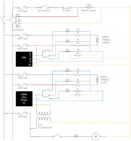
RIMS v1.0.jpg
 
You would need to latch in your main power circuit with a set of contacts on the main power contactor around the "ON" switch.
What is the 12VAC transformer supplying to the PWM module? Or is it a 12VDC power supply?
Are those solid state relays supplying power to the elements? That is going to be a lot of switching for an electro-mechanical relay.
With the switches in the positions shown, the "top" of the elements are not connected in a circuit. Keep the top of the elements always connected, and just switch the "bottom" from the opposite 240V line and neutral.

Not sure what you are talking about latch in the main power circuit. The power swith is a maintained switch, with that on, won't it energize the contactor as is? I guess I don't understand. I really only have experience with DC current.

Yes, the transformer is for 12v DC current to power the 555 board.

I did forget to label the relays for the elements. Yes, they are 40A SSRs.

The top switch isn't really needed in either element circuit, yes, but with that, I can kill the control voltage to that SSR as a safety feature. I can and may eliminate that for simplicity, but should opperate as drawn, no?
 
If you have a maintained "ON' switch, you can kill power with the "E-STOP", but when the E-STOP is reset, if you forget to open the "ON" switch, power will automatically come back on. You should put a set of normally open contacts from the power contactor around the non-maintained "ON" switch. That way, when you hit the E-STOP, power will drop out and you have to intentionally push the "ON" switch to turn power back on.

I was looking at the two switches coming off of the controllers as one 2-pole switch. My mistake, it makes more sense as an SPST and an SPDT switch. Just remember that you'll have to turn the bottom switch to 120V position when you kill SSR power for safety, or you'll still have the power connected on that side.

As far as the bottom SSR goes, there is really no need for that. You don't need (or really want) to switch your neutral. You really could get away with not having the middle SSR either. A single electro-mechanical relay to switch between 240/120 for that would work. You really only need to control one leg with an SSR.
 
Ah, I do see now. Thanks for the clarification.

I will look for a 40a relay that will allow the NC contacts to be hooked to neutral and the powered closed contacts to be hooked to 120, that way, the element remains hooked to neutral for safety. That would simplify my switches too. I could use two SPST switches instead of a SPST and a SPDT.

Thanks!
 
I will look for a 40a relay that will allow the NC contacts to be hooked to neutral and the powered closed contacts to be hooked to 120, that way, the element remains hooked to neutral for safety. That would simplify my switches too. I could use two SPST switches instead of a SPST and a SPDT.Thanks!

I am not sure if you mean two SPST switches per element, or two SPST switches total. I believe you just need the latter.

Like evanmars suggested, you really should be using an SSR to switch the power on/of from the PID/PWM. The relays will quickly wear out. Not to mention driving you nuts with their constant clicking.

My suggestion: Replace the relay of the upper element connection with an SSR, switching L1 on/off to the element. Put a 40A SPDT relay switching L2 or Neutral to the lower connection, which I am sure you already are planning to do. Now the only SPST switch you need for this element is to switch the coil of the SPDT relay on for high power and off for low power.

Edit: Now I think you are planning on using the second switch to turn off power to the upper relay/SSR. That is actually a good idea. I think you have it figured out.
 
Ya, those relays are supposed to be SSRs, but, I had to settle for a relay picture. I forgot to mark them.

I looked around last night and I am having trouble finding a SPDT 40a relay. I have found a 30a at a reasonable price, so maybe I need to reduce one of my elements down to 2500w so I draw less than 30a safely.

Ya, when I re-draw this, it will have one switch to kill power to L1s SSR and another to control L2/Neutral switching for each heating circuit, so 4 element switches total.
 
I think it's important to distinguish a contactor relay from an SSR (solid state relay)....it's kind of confusing in this thread for those of us lurkers. Something to think about too....SSRs will fail closed....so if you forget to switch off the contactor you could have a situation where the element is still on even if the PID isn't sending the "on" signal to the SSR.
 
I looked around last night and I am having trouble finding a SPDT 40a relay. I have found a 30a at a reasonable price, so maybe I need to reduce one of my elements down to 2500w so I draw less than 30a safely.

If it's that much cheaper/easier to use a 2 pole contactor, you can just use one of the poles.....just don't put both elements on the same contactor!!!!!
 
You're right SS. I will be editing the original picture tonight to represent SSRs, then re-drawing some items.

I will look into adding a contactor to cut total power to the elements as a final say as well.
 
Lol...ya, if it weren't for this board and people who know what they are doing, this project wouldn't get off the ground. I do have a friend who is an electrician, I plan to have him check over my work as well to make sure its safe.

I like stuff like this. It has always interested me. I was pretty close to going to ITT Tech for their EE program.
 
Made some changes. Incorporated contactors for both elements as a final say safety.

I split the 2 RIMS elements into separate switched 120/N legs. As shown, each leg has it's own switched SPDT relay, however, I may just wire it with a single DPDT relay that would function the same. I haven't sourced all parts, so cost will be a factor.

Also added was the momentary power button and relay.

The switch that controls the relays that select 120/240 for the RIMS elements also controls the relay that selects 120/240 for the kettle. This will allow me to run the kettle in 120v mode while sparging without drawing too many amps. Sure I could simplify by having my RIMS contactor control switch also double as an lock out for the kettle when the RIMS is running, but I imagine I will be able to save some time heating (or maintaining) my runnings....maybe not???

My understanding of a 555 timer PWM board is that it needs to run on low voltage, but it seems like I've seen otherwise. Do I need that 12v transformer at all? Can I run it off of 120v? That would also simplify.

Also, sorry it's not of great quality, I'm by no means a professional.

Thanks!!!
Steve

RIMS v1.3.jpg
 
Made some changes. Incorporated contactors for both elements as a final say safety.

Steve, you are doing a lot of stuff that I'm also planning to do, for example the interlocks preventing all elements to run at high power. You are a bit farther along than I because I don't have a schematic yet.

I get a little lost trying to figure out what you are trying to do. Perhaps having consumed several pints of 7% abv brown ale has something to do with it. I can see one thing though that is not going to work. The indicator lamps, for example the power-on lamp, cannot be connected in series with the contactor/relay coil, they should be connected in parallel with the coil.

My understanding of a 555 timer PWM board is that it needs to run on low voltage, but it seems like I've seen otherwise. Do I need that 12v transformer at all? Can I run it off of 120v? That would also simplify.

It is not going to like 120VAC, guaranteed. The 555 will need something like 12VDC or less. I am not familiar with the details of this particular board, but I have used several 555 timers over the years and they are running from some low voltage DC, not AC.
 
Steve, you are doing a lot of stuff that I'm also planning to do, for example the interlocks preventing all elements to run at high power. You are a bit farther along than I because I don't have a schematic yet.

I get a little lost trying to figure out what you are trying to do. Perhaps having consumed several pints of 7% abv brown ale has something to do with it. I can see one thing though that is not going to work. The indicator lamps, for example the power-on lamp, cannot be connected in series with the contactor/relay coil, they should be connected in parallel with the coil.

It is not going to like 120VAC, guaranteed. The 555 will need something like 12VDC or less. I am not familiar with the details of this particular board, but I have used several 555 timers over the years and they are running from some low voltage DC, not AC.

After drawing this up, I see how complicated I've designed it. There are definitely areas where I can simplify.

I didn't know that about the lamps, are you talking about all of them not being able to be run in series? Guess I need to research 120 some more, I know in 12v apps, it would work. However, thinking about actually wiring the power on lamp, I would have to run a wire from the switches down off the door, to the relay, then back onto the door for the lamp. I will have to update that.

I'll have to also look at the 555 circuit. I thought they were only low voltage as well. With that 12v transformer, I could run all of my switches 12v and all of the relays/contactors could have a 12v coil. this would make the swap to BCS/Brewtroller easier if I ever went that route in the future.
 
I didn't know that about the lamps, are you talking about all of them not being able to be run in series? Guess I need to research 120 some more, I know in 12v apps, it would work.

Yes, had this been a DC system and the voltage was slightly high, say 14V, it would indeed work to have plain LEDs in series with the coils. I have done that, but you would have to check that the coil current is in a range usable by the LED. 120V AC lamps, even those made with LEDs, are made to run with the full system voltage so they need to be connected in parallel.
 
Back
Top