Help/Advise on PID problem

Homebrew Talk - Beer, Wine, Mead, & Cider Brewing Discussion Forum

Help Support Homebrew Talk - Beer, Wine, Mead, & Cider Brewing Discussion Forum:

This site may earn a commission from merchant affiliate links, including eBay, Amazon, and others.

lcat45

Well-Known Member
Joined
Apr 27, 2012
Messages
94
Reaction score
2
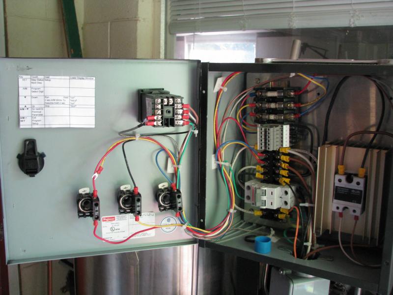
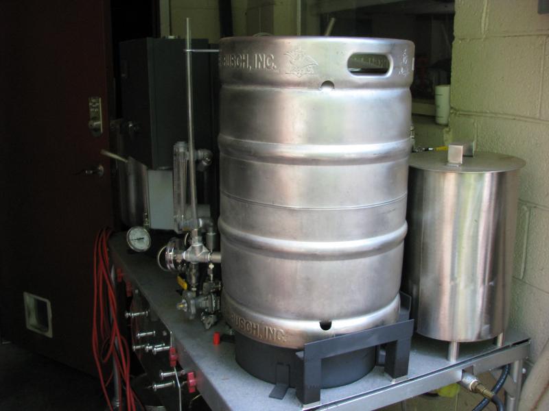
I have been trying on and off to resolve a PID/thermocouple (J type) problem since I've had this system was put together....the problem is the PID has never read the correct temperature and I've tried two thermocouples from 2 different suppliers and know one at least works....have worked very closely with Auber Instruments and their support is really good, but the thermo didn't work on my system even though after sending it back they ran a test and found it to be in working order, so that leaves the PID also from them and it appears to also work correctly.......they at one point suggested it was an inductance problem and that is certainly a possibility but I don't even know how to test that any further than reroute it as I've done with no difference.....I have enclosed 2 pics of my system to show the setup....the pid is behind the small tank as the hot wort comes out of the tank and goes to the MT where it is recirculated....the other pic show the back of the thermo to show that it does come up through an electrical enclosure that also has everything else crammed into it to get it to the panel.....I have even removed it from the routing under the table and just ran it over the top of everything to see if that made a difference, but zilch, nada had made a difference....anyone have any ideas to try next....the only thing I'm trying to do is manage the temp of single or multi step mashes....thanks, Lee
IMG_0921.jpg


IMG_0922.jpg
 
Lose the terminal lugs, the dissimilar metals will throw the readings off, just land the wire directly to the PID controller. With thermocouples the wire is two different metals, joined at the junction, any splices of other types wire will screw the readings up
 
Thanks kladue for the reply.....don't question your judgement but that's the way it came from the mfg and I would think it would be different if that was a requirement......don't mind doing it as it's not working anyway, so nothing ventured nothing gained I guess....thanks
 
Is the indicated temp off a couple degrees, or off by about 30 degrees or more.
Most of the controllers offer an offset value you can use to correct for small temperature differences < 20 degrees, display difference values that are more than that amount is usually caused by a wrong thermocouple selection in the controller, or wrong thermocouple type installed.
Another thing to check is the wire colors on the thermocouple, white /red is a type J, yellow red is a type K which seems to be more readily offered. If you were sold a type J, it should be white/red, not yellow/red type K.
 
Thanks again for the reply.....yes it is red/white and I cut off the connectors and used bare wire and it didn't make any difference.....I tried to calibrate and put it in water with a lot of ice...had to put in an offset of -10 to get it to go down to 32 but when I placed it in some hot water the temp on the unit changed but was about 30 less than the water temp should have been....I"ve even gone through all the options of changing the type from all the values in the book that it should work with and none of them work either as I was thinking it was sent as a different type than ordered.....I'm at the point now of starting to look at other options as I wanted to add a lot more automation in valves and temp monitoring so if I didn't need to make some beer soon I'd just give up on it and start heading in another direction to go with some other ways of doing the same and more...any other ideas appreciated or any other alternatives also open for consideration.....many thanks again
 
The PID unit sounds suspect as there is supposed to be a cold junction reference circuit built in?, which if working correctly should have made the offset a couple degrees at most near freezing and it should have tracked across the span. Alternative approach would be to use a 100 ohm RTD sensor instead of the thermocouple as this just uses an internal amplifier circuit, not a cold junction chip.
You get what you pay for with the budget controllers, some essential things are less than perfect which give you the problems you are having when using thermocouples.
 
Actually I did try one from Auber Instruments and it never worked for me either....I sent it back and they tested it and said it did work so I'm of the opinion that the PID itself doesn't work properly at this point but I kept thinking that maybe it was an inductance problem and nothing else but that apparently isn't the case.....think I'll just start a new thread and ask for suggestion on doing a new system from people who have experience with systems that do work and one that is current and can be expanded to do what I may want to do in the future...any input appreciated....regards
 
I assume you've configured the PID to the proper type of sensor/sender, right?

I had made the mistake of simply hooking up a sensor to a 2nd-hand PID, and it wasn't configured for the K-Type sensor I was using. Turned it off, picked the right configuration on the PID, and it immediately read correctly.

MC
 
Yeah Canuck, I have actually tried every one that the PID supports and none work with the J type that I have.....I'll probably send it back to the supplier and see if it's bad or if they can figure out what's wrong....bout over working with pids and this whole setup.....need a system that works...not into troubleshooting forever...would be nice to be able to make a brew once in a while....thanks
 
Yeah Canuck, I have actually tried every one that the PID supports and none work with the J type that I have.....I'll probably send it back to the supplier and see if it's bad or if they can figure out what's wrong....bout over working with pids and this whole setup.....need a system that works...not into troubleshooting forever...would be nice to be able to make a brew once in a while....thanks

I've found K types to be a bit more common. I've been using K's from Auber.

MC
 
Actually MC the last one I tried was from Auber and they were good about trying to help me find out the problem as we did a lot of troubleshooting but didn't come up with anything....
 
This probably won't solve your problem but I wouldn't zip tie your TC wire to other high voltage lines. I would keep them separated as much as possible. TC's generate extremely small voltages and unless the wire is shielded it will pick up noise from nearby high voltage wires.
 
Thanks crane and Junkster for you help.....still having the problem but don't think I will pursue it any longer..want to start adding more automatic functions to my system so I'm not looking for suggestion from people who have systems already running and sort of match what I want and am going to abandon this year long off and on maddening endeavor.....thanks to all who have tried to help....really appreciate your advise....regards, Lee
 
This probably won't solve your problem but I wouldn't zip tie your TC wire to other high voltage lines. I would keep them separated as much as possible. TC's generate extremely small voltages and unless the wire is shielded it will pick up noise from nearby high voltage wires.

BINGO! I couldn't tell from the pics if this was actually the case but high voltage/supply lines should not be anywhere near signal lines. Its called EMC - Wikipedia if you would like more information (Electromagnetic Compatibility).

The suggestion of inductance having something to do with it is probably correct. Especially if the high voltage/supply lines are AC. Changes in current will create a magnetic field that could create inductance in other lines.
 
Yes huntb I did have everything run up through the same guide but what was I found out that it didn't work any better when I removed it from the influence of the high voltage and simply ran it over the top of the unit and made the connection to the pid and the numbers were still the same or at least not correct.....from there I was out of ideas and frankly just over dealing with trying to make this arrangement work...... plus under the way things are laid out I would have to find another way to route everything so to me it now seems more sensible to just work on another solution that will give me more flexibility and automation.....so not I'm following some of the threads of other people who are asking how to automate their system and see what develops as I need to following another path.....thanks to everyone who so generously replied...regards
 
I didn't think that the influence of high voltages would be the cause of the problem here, just a best practices tip. If the high AC voltages were affecting the TC reading you would expect the readings to bounce all over the entire input range of the device.

Have you tried a different sensor type like a thermistor or RTD?

Are there any jumpers on the controller that would change the biasing for different sensors?
 
lcat, I've had similar problems caused when the inside of my panel was getting really warm. If the junction where the thermocouple wires are connected is a different temperature than the back of the PID, you'll get a sizable offset.

The back of the PID contains a small diode which is the "cold junction" reference. You might be able to see it through the holes... it's a small orange/brown device hanging in the air. Try blowing a hair dryer at the back of the PID for a moment and see if the temp on the display changes. Or run your system with that door wide open like in the pic.

The solution might simply be to get that heat sink outside the box, or to add a fan.
 
does this problem occur if you were to run the system with the front panel open, like in the first picture??
 
It doesn't sound like the cold junction sensor is causing the problem because the problem would have gone away when you switched to the RTD.

My next step would be to completely remove the controller an all of the TC wire and sensor from your setup. Then safely connect up the TC and power to the controller. If the problem still exists then send both the controller and TC to auber for failure analysis.

If the problem goes away when you isolate the controller and sensor then you know it is from your setup and not the controller or TC.
 
Thanks again craine....my next step is to send it back and have them check it out without going to all the trouble myself...I think they are better set up do to so...may be cutting off my nose to spite my face but I'm just over it even though at the moment all I really need to work is being able to hold the grain at the correct temps for the time needed to get the grain conversions done....oh well...maybe they can find something concrete....thanks again,,,regards
 
Back
Top