Diagram Critique - My "Brutus 20-10"

Homebrew Talk - Beer, Wine, Mead, & Cider Brewing Discussion Forum

Help Support Homebrew Talk - Beer, Wine, Mead, & Cider Brewing Discussion Forum:

This site may earn a commission from merchant affiliate links, including eBay, Amazon, and others.

shortyjacobs

Well-Known Member
Joined
Aug 12, 2009
Messages
2,509
Reaction score
46
Location
Twin Cities, MN
Here's my plan for my electric upgrade. Please give me any and all feedback. The system will be a 10 gallon model of jKarps's Countertop Brutus 20, sort of, with the addition of a RIMS tube. 1 BK/HLT (15 gal keggle), 1 MLT (15 gal cooler), 1 pump.

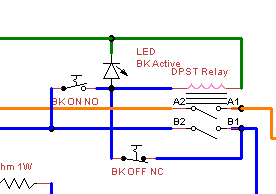
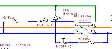
The thing I'm most proud of is the On/Off circuit for the RIMS and BK elements. Push the "on" momentary NO switch to activate the relay circuit and the elements go live. Push the "off" momentary NC switch to deactivate the relay circuit and the elements. When power is cut, the relays open automatically, so the design "fails safe", and also "starts safe", since there's no way the relays can be left on when power is cut, then run dry when power is restored. I thought this was a real novel design, until I realized all red pushbutton momentary switches were NC, and all green ones were NO. Obviously I wasn't the first with this idea. Here's the switches from AD: Red, Green.

Here's the design - click to embiggen: EDIT: Newest Diagram now in Post 14!


Thoughts? Suggestions?

(oh, diagram was made in something called TinyCAD. It's my favorite so far for wiring diagrams - super easy to use, not so much of a huge emphasis on PCB diagrams like so many wiring programs)
 
Check your power path on the 2 LEDs (RIMs off & BK off switch paths). It needs to be changed as the LEDs are in series with the relay coils.
 
Thanks for looking P-J.

EDIT: OH! I might understand. Because the LEDs are in series, and because LEDs are high resistance and therefore low current flow, having them in series might not pass enough current through to keep the coil actuated. Is this what you're saying? If so, ignore what I typed below!

I think that's what I want? I want the LEDs to light up when the relays close...when the relays are open, they should be unpowered, (first picture below, grey lines are unpowered). When the relays are closed by the NO contact, and then the NO switch is released, the situation, as I understand it, becomes the second image below. (I took the NO switch out of the diagram in the second image for clarity....it will be OPEN, so no power through it)

Undjgs.png


To be clear, I don't want the LEDs to flash as the SSR switches the heater on, I want the LEDs on constantly whenever there is power supplied to the SSRs, (when they are live). Does this work?
 
Looks nice. I like the latching relays. I used a bunch in my HLT panel.

Are you just using an LED or a 120V LED indicator lamp? With just an LED you need to set your current with a resistor and a few more components are needed to wire an LED to 120VAC. The series circuit with the relay coil could work I guess but I would parallel the LED somehow.

Ooops, I misspoke. I use these currently on my panel, I like em because they are small, (not a fan of the 22mm indicators).

http://www.radioshack.com/product/index.jsp?productId=2102794

120V neon lamp, whatever that is.
 
Oops. One more mistake. For some reason, I was thinking of the alarm relay outputs as power outputs, not relay contacts. I was thinking of them like I think of the SSR outs, where they have a hot and a neutral. They are relays, not outlets, so I need to supply hot voltage to one side of the relays, and connect the other half of the speaker buzzer to NEUTRAL....updated my picture (click for big):

Edit: Newest diagram in Post 14
 
I didn't pay much attention to that part of your circuit. You are correct. Those are relays. I cant see the circuit so well on my phone but have you planned for fuses?
 
No fuses in there....I'm afraid to complicate the wiring even more, honestly. If I did put em in, I figure I'd want 5 amp for the pump, 10 amp for the aux, 15 amp for the 120V RIMS, 30 amp for the 240V BK element, and 1 amp for the relays, PID, etc?

Fast blow or slow blow? I don't really know what those mean...
 
You are feeding from a 30a breaker right? If so, your element wiring should be #10 and that is protected by the breaker. If you want to use smaller wire for the rest of the circuit fuse it down. I use #14 with a 15a fuse.
 
You are feeding from a 30a breaker right? If so, your element wiring should be #10 and that is protected by the breaker. If you want to use smaller wire for the rest of the circuit fuse it down. I use #14 with a 15a fuse.

That was my plan. 30A breaker going to the dryer outlet. dryer cord from outlet to spa panel. 6 AWG from spa panel to control panel. 10 AWG inside the panel for the BK element, (or maybe 6 AWG if I can make it work....I have a bunch of 6/3 wire lying around, which is why I'm going to use it). 14 AWG for all 120V <15 amp stuff. That makes sense, I only have to fuse the 120V after I split off the legs for the 240V element, so I only need to fuse at the beginning.

Updated image again. Added a master power off switch and DPST relay at the tippy top. Split off the 240V element first, then run the E-Stop circuit, (which will most likely be with 14AWG, but the resistors are my fuses, don't like having actual fuses in my e-stop circuit, more points of failure there), then I hit a 15A fuse. After the 15A fuse, everything's 14AWG, except SSR control and buzzer wire. Buzzer wire will most likely be 18 or 22 AWG, but it runs 120V still, so it's fused down to 1A. SSR control is 8V DC, and I'm not worried about fusing that.

Click for big.

 
I would tie the control wiring for the bk element relay in after the 15a fuse also. Your toggle switches should be rated 15a 120v right?

Sorry, it's difficult to see on my phone.
 
I would tie the control wiring for the bk element relay in after the 15a fuse also. Your toggle switches should be rated 15a 120v right?

Sorry, it's difficult to see on my phone.

Yeah, I was hesitant to tie in that wiring, simply because it made my diagram messier.....I figured I'd either make it out of 6 awg or run 14 awg and put it after the fuse....I was worried my diagram was getting too complicated to understand though, I have crap going everywhere now! I liked the idea of each latching relay running off the same power going through the relay, but with the different gauge wire I have to make it a bit less modular, I suppose.

Switches are all at least 15A/120V, some quite a bit more.
 
OK. So I can't figure out how I'd run control wiring for the BK from after the 15A fuse. The problem is the latching relay circuit:

4TNeu.png


I COULD run 14AWG wire for the NO "on" switch from after the 15A fuse, no problem. BUT, once the relay latches, power HAS to come from the 120V, 30A leg on the output side of the relay to maintain coil power to keep the relay latched. What I'm saying is, the part of the circuit that runs through the NC "off" switch has to be coming from a line that has 30A service.

I suppose I could use 14 AWG wire for that circuit, through the NC "off" switch, and put a 15A fuse in there as well, but I think that would be more hassle than just running 10 AWG wire for the whole control circuit. The NO and NC switches are only rated 130V 6.5A though!! and say they only take a max of 14AWG wire. ****.

So I guess, for the control circuits, I need 5A fuses before EACH switch to be fully protected? Bugger, that's 4 extra fuses, and a lot of extra wiring....

It would have to look like this then?
JBdIq.png
 
Back
Top