Electric burners - Any builders out there?

Homebrew Talk - Beer, Wine, Mead, & Cider Brewing Discussion Forum

Help Support Homebrew Talk - Beer, Wine, Mead, & Cider Brewing Discussion Forum:

This site may earn a commission from merchant affiliate links, including eBay, Amazon, and others.
With the system you are about to put together (one contactor, one element, one PID, temp probe, pump outlet), the only thing you have to do to make it a HERMS system is put your immersion chiller down in the kettle and pump wort through it.

I have been brewing on my HERMS for a year now and I only have one electric kettle. I don't see the need to make a dedicated electric HLT. The only time I even need a third vessel is when draining my first runnings to the boil kettle (there's two vessels) and needing a place to hold some hot water (there's the third). At no other point is there a third vessel involved.

So are you suggesting to keep it simple as in the first schematic?

One issue I have been running into with my current set up is a lag time when I need to get the sparge water ready. So for example, we do the first runnings off a 10G batch, into the BK. When the mashtun is drained, I add sparge water to sit for 10 minutes and then drain into the BK. Then I fire up the BK and we are off to boil. But I am stuck using a 30qt aluminum pot on my stove (in the house) to get that up to the sparge temp because the BK is collecting wort. It takes forever in the house, like 20-30 minutes or more to get to 170F. I was thinking if I had a second element in a HLT, I could get the sparge water going at the same time that I am collecting my first runnings, and do it faster than I can on my stove.
 
I see your point here. Two questions:

1. wouldn't the breaker in the subpanel just trip with two elements accidentally on?
2. Do you have an example of that switch you could pass a link from?

I am upgrading my subpanel to 100amps, but was only planning on putting in a 30 GFI breaker for the brew panel.

1. Yes. The breaker will trip if you turn them both on. My point was that you can avoid that. :)

2. Lots of examples of that around. Did you order from mouser yet (thus commiting mistake #1... Again... Ordering parts before you were done designing).
 
So are you suggesting to keep it simple as in the first schematic?

One issue I have been running into with my current set up is a lag time when I need to get the sparge water ready. So for example, we do the first runnings off a 10G batch, into the BK. When the mashtun is drained, I add sparge water to sit for 10 minutes and then drain into the BK. Then I fire up the BK and we are off to boil. But I am stuck using a 30qt aluminum pot on my stove (in the house) to get that up to the sparge temp because the BK is collecting wort. It takes forever in the house, like 20-30 minutes or more to get to 170F. I was thinking if I had a second element in a HLT, I could get the sparge water going at the same time that I am collecting my first runnings, and do it faster than I can on my stove.

With a HERMS system, the water that you are using (the water that the copper coil is sitting in) to maintain you mast temp *is* your sparge water.

When it's time to drain first runnings from MLT, I move the hot wate out of my e-kettle and into a large pot. Then I pump MLT to e-kettle and start heating to a boil. Then I move the hot water out of that temporary large pot into MLT for sparge.

Compared to a HERMS with a dedicated HLT, the only extra "work" I do is pump water from one tank to another one time. And I avoid a second contactor, second receptacle, second plug, second cable, second mounting kit for an element, and a seconf element. All of that "second" stuff adds up to maybe $60 or so.

So, spend $60 to save 5 minutes of time... Nah. I'll just take the 5 minutes and pump water.
 
What about the 4th switch on the second diagram - doesn't that prevent two elements from ever turning on?

EDIT: simultaneously turn on
 
With a HERMS system, the water that you are using (the water that the copper coil is sitting in) to maintain you mast temp *is* your sparge water.

When it's time to drain first runnings from MLT, I move the hot wate out of my e-kettle and into a large pot. Then I pump MLT to e-kettle and start heating to a boil. Then I move the hot water out of that temporary large pot into MLT for sparge.

Compared to a HERMS with a dedicated HLT, the only extra "work" I do is pump water from one tank to another one time. And I avoid a second contactor, second receptacle, second plug, second cable, second mounting kit for an element, and a seconf element. All of that "second" stuff adds up to maybe $60 or so.

So, spend $60 to save 5 minutes of time... Nah. I'll just take the 5 minutes and pump water.


Gotcha - see my only problem with this is... I don't have a pump yet...
 
1. Yes. The breaker will trip if you turn them both on. My point was that you can avoid that. :)

2. Lots of examples of that around. Did you order from mouser yet (thus commiting mistake #1... Again... Ordering parts before you were done designing).

hahah I never do that !

I can probably grab something from HD or radio shack though. Mouser order is out already.... but I did buy extras! :(
 
I have to ask... Why exactly are you using your stove to heat sparge water?

The kettle and propane burner are not being used during the mash, right? You can heat water right there while mashing. then run that water into you big aluminum kettle just before you are ready to drain the mash tun.
 
Regarding your 4th switch in that second diagram. I didn't even see that one in there.

Yeah, it'll prevent 2 from coming on at the same time, but...

4 switches to do what 2 can do? and you partially defeat the purpose of using contactors, because that 4th switch has to switch the full 240v/30A load.
 
I have to ask... Why exactly are you using your stove to heat sparge water?

The kettle and propane burner are not being used during the mash, right? You can heat water right there while mashing. then run that water into you big aluminum kettle just before you are ready to drain the mash tun.

Haha - I was hoping you wouldn't ask....

The mash tun is direct fire - so it has been sitting on the burner for the entire mash, firing when needed.

I guess that could be rearranges somewhat, just not as convenient. it usually needs a brief fire at about 30 minutes
 
Regarding your 4th switch in that second diagram. I didn't even see that one in there.

Yeah, it'll prevent 2 from coming on at the same time, but...

4 switches to do what 2 can do? and you partially defeat the purpose of using contactors, because that 4th switch has to switch the full 240v/30A load.

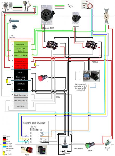
I redrew this so the switch was more visible (put it on the control panel face with the PID). I don't have the edited version at home. Anyway - it is supposed to be an on-of-on switch of 25amp or higher rating.

hmmm.... see what you mean about the 4th switch.
 
OK so the way I see it is that I have a couple choices. First is:
1. single element outlet or
2. double outlet.

I am leaning on double outlet since plugging and unplugging on the fly in a brew session poses a greater safety issue in my mind than flipping a switch (though I could be wrong there).

So now I either stick with the current design OR come up with a third design with that switch you mentioned. Because I respect your know how and can see the "engineering" aspect of your mind working toward simplicity (i.e. 2 switches instead of 4 - ha); I am leaning on the latter, create a third design.

Walker - Would you be so kind as to post a link to one of those switches from mouser? I can attempt to locate one locally. Additionally, if you could explain how they are wired, that would be great as well. I will attempt to work in a new drawing today with your better engineered concept. Thanks in advance!


A couple notes:

I should have mentioned, the HLT will likely be a dedicated keggle, or my megapot in my set up. My friend has a line in on a free keg (or so he told me), so if that pans out the HLT would be free. That is really the basis for us making it a permanent fixture.

The way I see it, even if I bought some extra $2.60 switches because I rushed the order, I am ok with that (shame on me :)). The key for me is having a well designed setup that makes intuitive sense and is safe when I am using it (more important than saving a few bucks).

My urgency to get this up and running is clear, because my chance at getting a free certified electrician inspection is coming up in 1-2weeks. So I want to get my build done by then so I can do a test run with him around. He is currently living in DC so it is tough to get him around.

To avoid confusion, I will be simply putting in 10g wire throughout my box. It might cost a little more, but it will be durable and avoid my making a simple wiring gauge mistake. As you said this is a current thirsty unit. There isn't that much wire in the panel, so I will take that one on the chin.
 
Don't order from mouser. You'll pay more for shipping than for the switch.

Radio Shack has what you need for like $3. I am on my phone, so cutting and pasting links is a pain, but I can post one later.

Or, walk in there and tell them, "I need a single pole double throw switch with a center-off position. Rated for 120V and at least 5A."

Wiring will be simple. There will be three terminals on the switch.

Center one will be connected to your power distribution block.

The other two terminals are for the contactors. One wire to each contactor coil.
 
I am going to hit up Radio Shack today on my lunch - So I will dig in their switch pile - but the employees are knuckleheads there (know less than I do, which isn't saying much).

So that switch replaces the three basic switches? Essentially, I am putting in a toggle on-off-on on the black power feed to each contactor.

So from black switch #6 to toggle on-off-on to each contactor. Ok that is pretty straight forward and saves a ton of wiring.

Thanks!
 
It looks like I would also have to split the wiring from the SSR between the two contactors. What is the best way to do that? Just go from one 10g wire to a Y splitting crimp?
 
Does your contactor usw screw-down terminals to connect load wires to? If to, I would just make a jumper wire to connect the two contactors together.
 
Everybody does it. :D

Even people who know that running a 240V element on 120V results in 25% power will forget that their 240V element falls to 84% power when run on 220V.

And now that I think about it, That means that my element is actually producing 5800 watts since I get 248V.

Sweet!

Er wait you lost me hear? :drunk: ha
 
Haha - I figured it was the wrong thread - I think jumpers it is. My new layoutis a lot neater, with much less wiring, and two switches. Looks much cleaner. Hence the saying... don't fall in love with your first draft.

Control Panel Box Wiring - Two Elements - Master.jpg
 
I bought both (knowing I will return one) - but the shack one felt a little flimsy by comparison. Power ratings are slightly more robust on the HD one. They are weird though like 6amp at 277v. Maybe it is because the switch is rated for use with a motor. I would assume the start up draw on a motor could have quite a surge.

I have to say Walker - I am very happy with the current outcome of this thread. Not only do I think the design will work well for me, I actually have learned a thing or two along the way - the best part of any project.

The show ain't over yet though! Let's see how I do on my final build ;)

I did pass along this drawing to my bro in law. He was really impressed. Likes the overall design and the safety aspects. He can't wait to crash over at my house and help install/do a test run. He even wanted to try to come over sooner to help me build the box.

Best of luck on everything. Don't hesitate to ask any more questions.

And remember that you are doing some stuff here that can really REALLY ruin your day if you goof up. Always be respectful of electricity.

One final bit of advice: put a small lamp inside the thing as an indicator that the thing is plugged in. It's easy to yank the cover off and not remember that you have the juice flowing. That little light will remind you that the monster can bite you.
 
Thanks for the tip about the light. How would you wire that in, aren't the lights 12v?

I was also thinking of putting a buzzer alarm in, but wasn't sure if the PID I have has an audible alarm on its own (saw a couple buzzer alarms in radio shack and it got me thinking). Would be cool to have an audible alarm going of for say, a strike water temp.

(need to read through that PID manual!)
 
One final bit of advice: put a small lamp inside the thing as an indicator that the thing is plugged in. It's easy to yank the cover off and not remember that you have the juice flowing. That little light will remind you that the monster can bite you.

Solid advice.. though I've started to trouble shoot mine with it plugged in even with the idiot light staring me in the face. I stopped before I did something stupid, but yeah - no hands in the box while it's plugged in.
 
:) I am scared to change a broken light switch or bad 120v plug (with the breaker off). Picture me with 3 pairs of latex rubber gloves on changing an outlet at my house! Fear can be good protection.
 
You can find 120VAC indicator lamps. Mouser has them... but oh... you already ordered from mouser. ;)

Radio Shack probably has some, too. And there should be some on ebay.

You would just connect it to one of the hot lines in your distribution block, preferably on the low current side of one of the fuses, and then connect the other side to neutral somewhere.

If it's plugged in, that light will be ON.

As for the buzzer... as far as I know, the PID doesn't have any built in buzzer or anything. It just has some little relay switches that it can use for alarm purposes. You would have to connect some actual buzzer and an appropriate power supply for the buzzer to the PID's relay terminals to pull it off.

Ohio Ed used a little DC power buzzer and a 9v battery in one of his builds.
 
Solid advice.. though I've started to trouble shoot mine with it plugged in even with the idiot light staring me in the face. I stopped before I did something stupid, but yeah - no hands in the box while it's plugged in.

Yes, sometimes you might have to open it and work on it with the power on, but then, when you figure out what is wrong and need to do the work, you'll want to unplug it. The light could hopefully remind you to unplug it.
 
Can you wire two 120V lights in series from one terminal? So hot out to first light, exiting wire to next light and return to neutral? I was thinking of mounting a light to the control panel face, and one inside to indicate "power on" Right now I have two hot terminals to use, so I would need to add another block, or wire in series. (was going to use the second hot for an audible alarm).

What would you recommend?

If you wire them in series, then they will only be getting 60V instead of 120V, so they wouldn't light up as much as they should.

You can wire them in series from black hot to red hot, though. That would be 240V total drop, with each light getting 120V.

Or splive the two lamps wires together and connect them to the same terminal block. Run them in parallel from that one hot connection to neutral.

Or...

you've got switches right there on the front of the panel that are getting a hot fed to them from the distro block and have screw terminals, right? You wouldn't be causing any problems by connecting two wires to the screw. Stack the spade connectors up and screw them down together on the switch terminal.

One wire bringing voltage in and one wire to a lamp. That's no crime.

I agree that it does seem "nicer" to have everything getting it's feed from the distro block, but you will find that your wiring might be cleaner if you piggy back some things here and there. As long as those things are tiny current devices, it won't be an issue.
 
So if I went the route of the switches (great idea by the way), I would take the hot (one from each of the switches) stack on my hot connection to each respective light and return them each neutral? Are you allowed to splice that neutral for a single return line to the terminal block? I am wiring it all in 10g so the return neutral would be 10g and 24o right?

It is a little tight in my project box, so this would actually help neaten up everything.

You shouldn't have any problem splicing the return neutral. The lamps will very likely carry only a couple of mA of current so it won't be a big deal.

Why the hell are you wiring everything with 10g? I mean, that's fine to do, but you can use wire that is LOT easier to deal with on the "low current" side of your fuses.

I think you will understand what I mean once you start trying to work with the 10G wire. That **** is thick and stiff and no fun at all. I used heavy wire ONLY to make the 240V path to my element. All other wiring was done with thinner stuff that was more friendly to install.

I actually hooked up all the wiring to my terminal block last night (the 10g is a pain, but it was easier to buy it all the same (I went with 5 ft of the white and green and 7 feet of the black and red). I have wire left over. I know it would have been easier to work with the higher gauge, but I wanted to make sure I didn't make a slip up and put 14g where 10g was supposed to go.

I even have been able to work in all my connections to teh hardware so far (except one switch which has the tabs and not the screws). But I will have to get creative there.
 
Here is one concern I have about sharing terminals on the switches with those lights. Since each switch is on a fuse (1amp FA and 2amp SA) will having the lights toast my fuses? If yes, will stepping up the fuses put the switches or the respective end hardware (PID, etc.) at risk?
 
Ok so in addition to my first fuse question. I wanted to know if it would be ok to splice the neutral from the contactors? Neither will ever be on at the same time, so I thought I could splice these, and this would leave me with a spot on the terminal block for my alarm (I have an email into auberins about how to wire the alarm as well - wasn't in the manual).

Here is the diagram with the addition of the lights.

Control Panel Box Wiring - Two Elements - Master.jpg
 
Your lights aren't drawing anywhere near 1A of current. It's likely in the mA, it's not going to blow any fuses.

The current going through the coil of your contactor is also very low, you shouldn't have any problem with daisy chaining the neutrals on those either. Mine was right next to the terminal block, so it just made sense to run them individually, but a single neutral in mine is daisy chained to all the other lights and switches. The outlet got it's own neutral though.
 
in fact, why does the alarm need it's own neutral? I made it a point to daisy chain all the neutrals on my front panel so that I'd only need to bring one wire for neutral up to the face of the panel.
 
Thanks Bruin. I almost daisy chained to the outlet but thought better of it.

I think I may have figured out the alarm wiring.

I think it is hot to #13 on PID; Daisy chained #1 and #14 on PID; hot from #1PID to on off switch (4PDT maintained type 6amp?); hot exiting switch to alarm; neutral from alarm to terminal block.
 
that's what I would do, all those things are mA current through them.. double check the alarm to be sure, I don't have one in my system.
 
Back
Top