50 amp wiring diagram help - brewtroller

Homebrew Talk - Beer, Wine, Mead, & Cider Brewing Discussion Forum

Help Support Homebrew Talk - Beer, Wine, Mead, & Cider Brewing Discussion Forum:

This site may earn a commission from merchant affiliate links, including eBay, Amazon, and others.

gnatp2

Well-Known Member
Joined
Jun 16, 2009
Messages
98
Reaction score
3
Location
Hoboken
Ok, so I'm sure this has some errors in it. But I'm hoping I'm at least close to getting everything right here.
I've been working on setting up a a control panel with the brains of a Opentroller DX1. I've stolen some ideas from other builds that I've been looking at and have compiled them into this.
-This is a 1 tier, 3 tank HERMS system
-2 heating elements (HLT and Kettle) and want to be able to run both at the same time
-a mixture of 2 way and 3 way valves to control all the flow
-4 temp probes
-2 pumps, 2 extra 120VAC sockets for future expansion if needed
-a ton of switches and LEDs for on/off/auto controlling all the valves, heating elements, pumps
-9 Lights indicating the current stage of the brewing process

My questions are:
1) Does the wiring look right?
2) I have a few circuit breakers in there (what sizes should i use), but are there any other means of protection I should be putting into the control box?
3) I plan on having the SSR's, 3 level terminal block and circuit breakers mounted to DIN rails. With the SSR's on DIN rails, will heat be getting trapped inside the control panel?
4) I haven't been able to find much documentation on the RGBIO8 boards. How do these get wired? Do you just hook up the swtiches on one side of the board, and the LED's to the other side? And then DX1 knows which position the switch is in and then controls the lights according to the switch position?

Thanks,
Nate

controlpanelwiring2.png


Here is the faceplate for control panel. Not completely done with the details yet.
https://www.oscsys.com/sites/default/files/vbtodrupal/ControlPanelFace.pdf
 
Nate,

Your post sparked my interest until you mentioned the BrewTroller.

I'm at a total loss with that. Sorry. I wish I could help.

P-J
 
Ok, so I'm sure this has some errors in it. But I'm hoping I'm at least close to getting everything right here.
I've been working on setting up a a control panel with the brains of a Opentroller DX1. I've stolen some ideas from other builds that I've been looking at and have compiled them into this.
-This is a 1 tier, 3 tank system
-2 heating elements (HLT and Kettle) and want to be able to run both at the same time
-a mixture of 2 way and 3 way valves to control all the flow
-4 temp probes
-2 pumps, 2 extra 120VAC sockets for future expansion if needed
-a ton of switches and LEDs for on/off/auto controlling all the valves, heating elements, pumps
-9 Lights indicating the current stage of the brewing process

My questions are:
1) Does the wiring look right?

Still getting started myself, but yes that will work... but see other comments below

2) I have a few circuit breakers in there (what sizes should i use), but are there any other means of protection I should be putting into the control box?

First, since this is a DYI job, look into getting a 50A GFI breaker to place in front or just after your wall receptacle as a safety and overall damage precaution. It'll kill your circut if any hot line grounds out and possibly save you and your equipment from major harm. This will also make it easy to put in a E-stop which just shorts a hot phase to ground through some big resistors (1kohm+) and causes the GFI to trip.

I would suggest placing a appropriately sized breaker in front of each expensive component in your diagram. I.e one for each pump and each element. For the 5V psu for the brewtroller you can get away with an inline fuse after the PSU as wall warts and AC--DC's are cheap.


3) I plan on having the SSR's, 3 level terminal block and circuit breakers mounted to DIN rails. With the SSR's on DIN rails, will heat be getting trapped inside the control panel?

DIN rails are awesome, but yes the SSR's will overheat that way. Get a large heatsink for both or individual ones are easy to find that are already sized for most SSR's. The heatsink should be external to the panel so cut a hole in the side and mount the SSR inside with the heatsink sticking out.

4) I haven't been able to find much documentation on the RGBIO8 boards. How do these get wired? Do you just hook up the swtiches on one side of the board, and the LED's to the other side? And then DX1 knows which position the switch is in and then controls the lights according to the switch position?

Thanks,
Nate

I don't know much specifically about this board, and it looks like since the brewtroller guys moved their website the links for manuals and schematics aren't working, so you might try calling them or emailing them
http://www.oscsys.com/store/product/1001707
 
Still getting started myself, but yes that will work... but see other comments below

WOW. No errors! I am shocked!
I want to be 100% sure that I have the wires correct because the last thing I need is to fry a couple thousand dollars worth or equipment or myself.

First, since this is a DYI job, look into getting a 50A GFI breaker to place in front or just after your wall receptacle as a safety and overall damage precaution. It'll kill your circut if any hot line grounds out and possibly save you and your equipment from major harm. This will also make it easy to put in a E-stop which just shorts a hot phase to ground through some big resistors (1kohm+) and causes the GFI to trip.

I would suggest placing a appropriately sized breaker in front of each expensive component in your diagram. I.e one for each pump and each element. For the 5V psu for the brewtroller you can get away with an inline fuse after the PSU as wall warts and AC--DC's are cheap.

Yes, I'm going to have my electrician install a new wall receptical from my main circuit breaker panel. I'll make sure he makes it GFI. Good suggestion.

I still need to research a bit more about E-stop. I'll look into that.


DIN rails are awesome, but yes the SSR's will overheat that way. Get a large heatsink for both or individual ones are easy to find that are already sized for most SSR's. The heatsink should be external to the panel so cut a hole in the side and mount the SSR inside with the heatsink sticking out.

These are the SSR's I am getting. http://www.oscsys.com/store/product/1001674 They already have a heat sink on them, but I kinda suspected that the heat would still get trapped in the box. You think I just mount a couple more heat sinks on the top of the control panel itself? And could I just use some heat sink compound and glue them on or do I need to cut holes in the control panel? I was hoping not to so I could keep it all looking nice, but I want to put safety first.
 
I've been thinking... (always dangerous)

Should I be using 10 gauge wiring as I indicated in my drawing? or since it is 50amps, should I be using 6 gauge? I'm a little confused as I have 2 hot lines to get up to 240 volts. I know the max with everything running will be a little under 50 amps, but I don't know if that means 25 amps for each hot line or 50 amps on each hot line? And if it is 50 amps for each hot, I'm guessing I need to bump up my SSRs to 50 amps?

Nate

With the SSR you linked, yes the heat will stay in the box but in that case you can probably get away with just puting in a fan blowing on the SSR's and a vent on the other side of the case or some other configuration that exhchanges air with the outside and has cool air flowing across the SSR.

Also I just noticed that you have neutral going to your elements. They probably only have 2 terminals which will be just the 2 hot lines and don't need neutral.

as for wiring, think about it in terms of the element. one terminal gets phase 1, and the other gets phase 2. Each AC phase is off from the other by 180 degrees so when phase 1 is positive, phase 2 is negative.

Electric-Household-2Phase


this means that each time the amplitude of each phase is at its peak, you get full current to flow on both the phase 1 and phase 2 line, but this current then reverses again just a tad later. in the case of your elements that's just short of 20Amps. So if you have a 50Amp breaker, both your hot lines need to be able to take the full 50Amps as the breaker won't trip till it hits that

Your ground line should be never ever see the full 50Amps as the GFI should shut down at something on the order of 5mA, but as a safety precaution its probably best to be the same size.

The neutral on the other hand will be different as it will only ever be completing the circuit for a single phase (unless you hook something up really wrong), so it only needs to be sized big enough to accommodate all the current from all of your single phase breakers, but again in the interest of safety, might as well just have them all be 6 gauge.
 
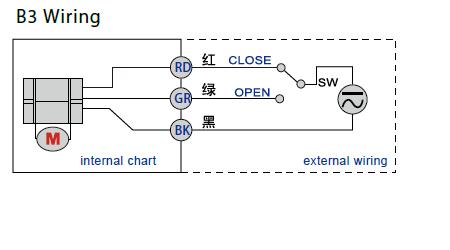
The only thing I'm unsure about is the 3-way valve wiring. I thought you needed SPDT relay support for those. Do you plan on running them from the 8 port relay board in the schematic?

S-
 
The only thing I'm unsure about is the 3-way valve wiring. I thought you needed SPDT relay support for those. Do you plan on running them from the 8 port relay board in the schematic?

S-

I was planning on controling the valves directly by the outputs of the brewtroller. There would be 3 wires for the valves. One would be DC+ all the time (purple wire in my diagram in post 1), one would be DC- (grey wire) and the third would be a DC+ trigger (blue) wire that would come straight from the brewtroller and move the ball valve to its secondary position.

BUT I think you might be right. I found the wiring schematic for these valves and I think I might have this setup incorrectly.

Here it is below. Let me know if you agree (I think you're right)... And any ideas on how to get around this? I guess I could just get more relay boards in there but I'd rather try to utilize the DX1's outputs directly from the board.

b3wiringKLDvalves.jpg
 
If you haven't purchased your relay boards yet, you could get the 8 relay SPDT board and wire your 3 way valves to that board. Your pumps could only use one side of the relay. I am ready to start building now, but I have the BT4.0 with the 16 relay SPDT board. I think this DX1 is much cleaner and a more streamlined system.

S-
 
So I've made some necessary changes and here's what I've come up with:
-10g wire changed to 6 gauge
-Upgraded SSR's to 50amps
-Removed circuit breakers after main inlet relay. I figure there is no need for a huge circuit breaker here since I'll have a 50amp circuit breaker in my main house panel
- Removed incorrect neutral lines from heating elements
- Instead of using the 12 output lines directly from the Brewtroller DX1 to the valves, the output lines now will power brew stage LEDs. (The LEDs will show you which stage in the brewing process you are as you can see from my front panel layout attachment in original post). 2 DX1 output lines still control the SSRs
- 2 8 port relay boards will control the valves and the 2 pumps and 2 extra outlets.
- Added E-Stop button before power key switch. Does this look like the right location for it in the system?

How does this look now? Any more recommendations?

controlpanelwiring3_0.png


Thank you!
Nate
 
Looks like I may need more than one 120VAC->12VDC power supply (the one supplied by OSCSYS is 5Amps)?
I was doing some calculations:
5 PID modules - 1amp each according to the website
3 RGBIO3 boards - 500mA each according to the webisite
I2C LCD controller - 100mA
LCD display module - unknown
Encoder module - unknown
Temperature probes - unknown
12 ball valves - 4Watts each. at 12VDC -> potentially 4amps total

This look right? Will I need 3 (maybe even 4) of these? Also makes me wonder if I'm going to be going over 50 amps total in the system if I have both of these heating elements going.

Nate
 
Did you end up using the DIN mount SSR's? I'm getting ready to cut holes for external heatsinks and ran across this. If you did use the DIN mount SSR's with the internal heat sink did you install a fan to pull air through?
 
Did you end up using the DIN mount SSR's? I'm getting ready to cut holes for external heatsinks and ran across this. If you did use the DIN mount SSR's with the internal heat sink did you install a fan to pull air through?

Yes, I used the DIN mounted SSRs with built in heat sinks from the brewtroller guys. I also have found a DIN mounted fan that I plan on putting in the control box. Although I finally have it all wired, I haven't fired up the system yet as I'm waiting for my electrician to install the outlet, so I'm not sure how hot the SSRs get.

Before buying DIN mounted SSRs, make sure you measure them. They take up quite a bit of room front to back (maybe 4"?, I can't remember), so make sure you have enough depth in your box.

Nate
 
Thanks gnatp2. I think I'm going to pull the trigger on the DIN mount SSRs. Do you mind sharing where you picked up the DIN mount fan?
 
I'm a newb at this, but looking at your wiring diagram, on the hot2 bus -> 120V to 12V, shouldn't you have the lower gauge wire to the circuit breaker/fuse?
 
Nate:

I am in the process of building a 60a Brewtroller based control panel and came across your thread. I have a few questions.

What values do you plan on displaying on the AUX1 and AUX2 PID displays?

How did you terminate the switches and LEDs on the RGBIO boards? What switches are you using? How difficult is the RGBIO board to work with? I know that OSCSYS still lists it as being in beta.

Are you having any heat issues with the DIN mount heat sinks inside of your control panel? Is your control panel vented?

Thanks in advance,

Matt
 
Although I now have my setup put together, I haven't had a chance to program the brewtroller, so mine isn't up and running yet.

For AUX1/2 PID modules, I was planning on either having them as timers (if supported) or for additional temperature monitors (maybe temperature of chiller water as it leaves chiller... or many other options as brewtroller allows for a ton of temperature probes). I personally think timers would be the best but I haven't seen if I can program them that way or not yet.

The RGBIO8 boards aren't the easiest things, but they aren't incredibly complex either. I am just using some DPDT switches from i got from ebay. I think radio shack sells them. Do a search for "DPDT with Center Off Heavy-Duty Toggle Switch Radio Shack". I used those for my larger switches that will control my heating elements and pumps. For the valves, I used the smaller switches that are available in the brewtroller store. The wiring for the RGBIO8 boards is fairly easy. One side of the board is for the inputs, you just wire 3 wires to the board and the 3 wires to your switch. And on the outputs, you just wire the 4 pins to your RGB LEDs. What I found more confusing is how to get the boards to be recognized by the Brewtroller DX1 and you also need to make a few code changes to the software that you upload to your DX1. I was a bit confused on it all, so I had to contact the brewtroller guys in their chatroom to help out. Hopefully the brewtroller guys put a more user friendly instruction manual out there on how they operate.

No heat issues yet as i haven't fired it up. But in addition to the plans I drew up here, I'm adding a 12v DIN mounted fan that should keep air circulating within the panel itself. If I find that it still gets too hot, I'll have to vent it.

I know you didn't ask this, but FWIW, I had planned on going 60 amp like you but decided to go with 50 amp instead. I found that 50 amp parts are WAY easier and cheaper to get, and all I needed to do was go with a 5500W heating element and a 4500W element instead of 2 5500W elements.
 
phlipot89 said:
Is there any updates on this build?
. What info are you looking for? I can't speak for Nate but completed my panel and have brewed on it once. I had to pack it up to move and am in the process of setting up my brew room at my new house.
 
How many power supplies did you use inside the case, he mentioned he may have to use many. Also couldn't this be adapted for 4 elements?
 
How many power supplies did you use inside the case, he mentioned he may have to use many. Also couldn't this be adapted for 4 elements?

One 5 amp DC power supply was plenty sufficient. I have a 5 amp circuit breaker and it has never tripped. It easily handles the loads of the PIDs and valves just fine.

Could definitely be adapted for 4 elements. You would just need to make sure you aren't running all 4 elements at the same time. Running one 4500 and one 5500w is fine for 50 amps. If you plan on boiling more than 12 or 15 gallons at a time, I personally would go with four elements (two for both vessels) to speed up the brew day. Right now I am 4 hours from starting to fill the HLT to flame out. About half my time is heating water/wort.

I have brewed probably 15 or 20 times on the system. I keep making improvements along the way and once I am finally happy with the final setup, I'll try to post a full updated diagram of the wiring and tumbling/valve profile. Feel free to ask any other questions in the meantime.
 
What changes would you make? you put it all in 1 box right? some have mentioned it would be nicer if it was in 2 boxes. 1 240 box for elements and 1 120 box for everything else. any thoughts?
 
What changes would you make? you put it all in 1 box right? some have mentioned it would be nicer if it was in 2 boxes. 1 240 box for elements and 1 120 box for everything else. any thoughts?

1 box worked for me. But 2 might make sense if you are going to go with 4 elements. Either way, make sure you have plenty enough room as it gets annoying to work in tight spaces
 
Also, what are all the switches for? You have 24 of them and 24 lights? I get the 12 valves but that are the others for?

I planned a ridiculous number of on/off/auto switches for everything (valves, pumps, heating elements). But so far I haven't hooked them up and haven't felt like I needed the additional override control. I have all the supplies to hook it up when I want ,but brewtroller does a fairly good job of allowing control within the program so I haven't felt the need.

If you wanted moderate additional control, I would suggest override switches for the heating elements and your pumps.
 
I know this sounds complex and mildly stupid or genius... Ill let you all decide. BUT.. couldn't a person make 3 control panels. 1 for low voltage stuff like control and sensors, 1 50A for the MLT and its elements, and 1 50A for the brew kettle and its elements.... Then you could have a HUGE system that would be continuous....

good, bad, insane?
 
phlipot89 said:
I know this sounds complex and mildly stupid or genius... Ill let you all decide. BUT.. couldn't a person make 3 control panels. 1 for low voltage stuff like control and sensors, 1 50A for the MLT and its elements, and 1 50A for the brew kettle and its elements.... Then you could have a HUGE system that would be continuous.... good, bad, insane?

Sure, but you would probably need a rather large service depending on what all is going on in the house. The low voltage won't draw much current but the other two would. I have a 60a panel that I am installing in my house with a 150a service. I fully realize that if I may trip the main breaker if other appliances are used at the same time. You would have to spend more cash because you will be duplicating panels.
 
One 5 amp DC power supply was plenty sufficient. I have a 5 amp circuit breaker and it has never tripped. It easily handles the loads of the PIDs and valves just fine.

Could definitely be adapted for 4 elements. You would just need to make sure you aren't running all 4 elements at the same time. Running one 4500 and one 5500w is fine for 50 amps. If you plan on boiling more than 12 or 15 gallons at a time, I personally would go with four elements (two for both vessels) to speed up the brew day. Right now I am 4 hours from starting to fill the HLT to flame out. About half my time is heating water/wort.

I have brewed probably 15 or 20 times on the system. I keep making improvements along the way and once I am finally happy with the final setup, I'll try to post a full updated diagram of the wiring and tumbling/valve profile. Feel free to ask any other questions in the meantime.
gnatp2,
Congrats on this project back in the day. I am piecing together a 15 gallon HERMS and building my own controller with Brewtroller Pheonix internals. It looks like your diagram links no longer work. Did you ever make a final diagram. Could you post it or send it to me? What would you change about it now that you have nearly a decade brewing on it?

Thank you,
LL
 
Back
Top