Control Products Dual Relay $60 Shipped on Amazon

Homebrew Talk - Beer, Wine, Mead, & Cider Brewing Discussion Forum

Help Support Homebrew Talk - Beer, Wine, Mead, & Cider Brewing Discussion Forum:

This site may earn a commission from merchant affiliate links, including eBay, Amazon, and others.
I am just getting ready to wire one of these. I noticed in previous posts that the controller relays are rated to 20 Amps. The paperwork that I got with mine says only 8 amps if both relays are running at the same time or 16 Amps if they are not. Anyone know what the story is? It is not a big deal since the heater will not be running the same time as the freezer and neither draws 16 amps, just curious.

The only instance where you'd have both relays on is if for some reason cooling or heating on one relay does not keep the temperature in range and you've set the next cooling or heating relay to kick on behind the other one. Hypothetically possible, but not sure under which practical conditions it would be necessary.

For example, say I have one freezer inside a bigger freezer and both of them are hooked up to the controller, one on each relay. Say my beer is fermenting so uncontrollably it causes a nuclear reaction and the temperature skyrockets. Since I've set the first freezer to kick on at 66 degrees, and the second freezer at 72 degrees, both of them eventually turn on and somehow successfully manage to cool it down. Or they don't.
 
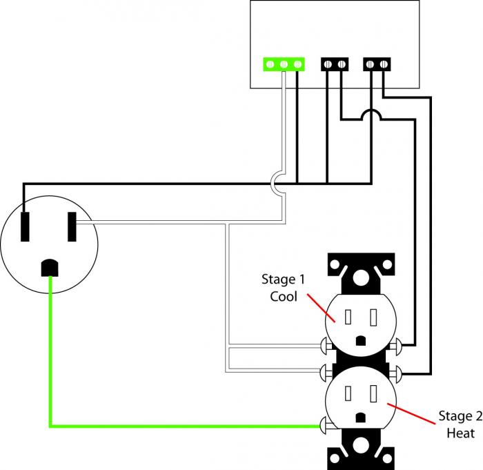
Grabbed a file from another thread/user and made it (hopefully) a little more understandable. Seems to be working for me so far.

IMG_1723.jpg


TC-9102 wiring.jpg
 
Nice drawing! Color coding the two screws gold would make it a little bit more newbie-proof.
 
Just thought I'd add my $0.02 here. If I can do this (with the help of the awesome HBT community!), anyone can!

Parts List:
1x Control Products TC-9102D-HV
2x Cord Grip 0.5"-0.625"x1.65" (Grainger part# 5D725)
2x Locknut (Grainger part# 5XC30)
1x Stainless Steel Wall Plate (Lowe's part# 156713)
2x 15A Common Back/Side Receptacle (outlet) (Lowe's part# 22375)
1x 50' 14/3 Outdoor Cord (Lowe's part# 242130)
1x Pack of Wire Nuts (Lowe's part# 47307)
1x Sleeving, 3/8", Expandable Braided, 10' (Grainger part# 2RMC7)
1x 8"x6"x3" Project Box (RadioShack part# 2701809)
1x Panel Mount Fuse Holder (RadioShack part# 27003640)
1x Pack of 10A Fast Blow Fuses (RadioShack part# 2701015)
~ You will also need a soldering iron, different colors of electric tape, and a multimeter

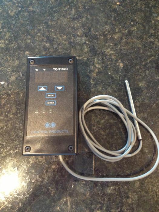
Pic 1: How the controller comes out of the box
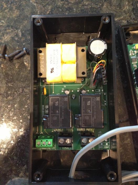
Pic 2: Taking a look inside
Pic 3: Inside; locate the relays and familiarize yourself with them
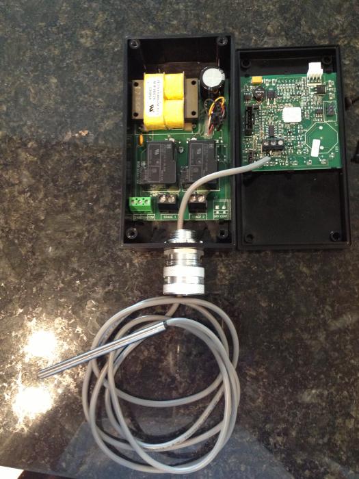
Pic 4: Inside; be careful with the wires on the probe, I'm sure they are delicate
Pic 5: Used a Dremel to enlarge the hole for the wire grip to fit

Ferm Chamber 01.jpg


Ferm Chamber 02.jpg


Ferm Chamber 03.jpg


Ferm Chamber 04.jpg


Ferm Chamber 05.jpg
 
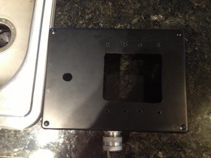
Pic 6: Use the Dremel with a cutting disc to cut a hole for the receptacle(s) you will be using, and a drill with a bit for the fuse holder. They don't have to be pretty, they'll get covered in the end. I used 2 outlets for no great reason, I'll probably add a computer fan (or two). The outlet on the left is for the cooling stage and the one on the right is for the heating stage (which I have not needed to use yet). If I were to do it again, I would cut the holes in the lid, not the box itself...
Pic 7: Drilled guide holes to mount the receptacles. I think if you tried to do it without the pre drilled holes, the plastic project box would crack.
Pic 8: Test fit everything to make sure it fits, and looks good.
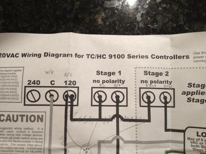
Pic 9: My notes on the included wiring diagram. Since I was going to have 5' between the project box and the controller, I used the colored electric tape to keep track of the wires.
Pic 10: Starting from the left you have the common white wire, black with red tape, black with green tape, black with yellow tape, black with blue tape, and black with white tape.

Ferm Chamber 06.jpg


Ferm Chamber 07.jpg


Ferm Chamber 08.jpg


Ferm Chamber 09.jpg


Ferm Chamber 10.jpg
 
(Not shown) Using the wires from the inside of the electric cord that was purchased, cut half way (25') through the cord. Set the male plug end aside, you will use all 25' of it. With the female end, remove the female end of the plug, and cut the remaining length into 5' lengths. Strip the outer casing, so you can get to the 3 wires inside, and set them aside. With the soldering iron, tin one end of the 5 black lengths of wire, and one white wire. Label the black wires with the colored tape at both ends. Also, use a punch to punch out the hole next to the main hole for the probe (There is also one on the side that you may use if you wish)

Pic 11: After tinning all the wires, insert the tinned end into the appropriate relay point on the controller. Wrap the loose ends together in electric tape to slide them through the braided tubing easier.

(Not shown) Strip about 1' on the male side of the length of electric cord, so you can get to the wires inside. Solder the black wire from the power cord to one end of the fuse holder. Solder another length of black wire to the other end. I had to install the fuse holder, then solder the wires to it.

Inside one wire nut, wire together the black wire from the power cord (fuse holder), the black wire with red tape, the black wire with green tape, and the black wire with blue tape. With the other two black wires from the controller, wire them to the appropriate outlets. My black and yellow goes to the outlet on the left, and the black and white goes to the outlet on the right.

Using the other 5' lengths of wire that came with the black 5' lengths, cut 2 - 1' lengths of white and black wire.

In another nut, wire together the white wire wire from the controller, the white wire from the power cord, and 2 - 1' lengths. Connect one loose end to each of the outlets.

In another wire nut, wire together the green from the power cord, and 2 - 1' lengths. Connect one loose end to each of the outlets.

Pic 12: All wired up inside the project box. Use the multimeter to test all your connections before plugging in.
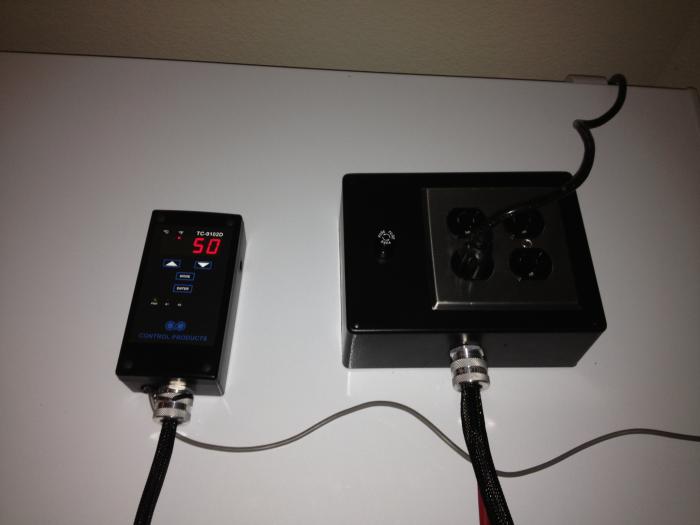
Pic 13: It's working!
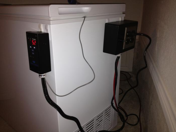
Pic 14: I used 3M Command strips to hang the controller and project box on the outside of the freezer (fermentation chamber)
Pic 15: Been holding a steady temp for 3 weeks now!

I hope this helped and wasn't more confusing!

Ferm Chamber 11.jpg


Ferm Chamber 12.jpg


Ferm Chamber 13.jpg


Ferm Chamber 14.jpg


Ferm Chamber 15.jpg
 
The only instance where you'd have both relays on is if for some reason cooling or heating on one relay does not keep the temperature in range and you've set the next cooling or heating relay to kick on behind the other one. Hypothetically possible, but not sure under which practical conditions it would be necessary.

For example, say I have one freezer inside a bigger freezer and both of them are hooked up to the controller, one on each relay. Say my beer is fermenting so uncontrollably it causes a nuclear reaction and the temperature skyrockets. Since I've set the first freezer to kick on at 66 degrees, and the second freezer at 72 degrees, both of them eventually turn on and somehow successfully manage to cool it down. Or they don't.

I emailed Emerson and got the "official" answer.

"The relays with the unit are 30A relays. UL though has listed this controller to a max rating of 20A through the relay. In the additional wiring diagram, this assumes the user will be jumpering over power to the controller from the power input side of the controller. It is assumed that the user will be using 110V power from a 15A circuit. If you do this, the maximum power you could ever achieve through the relay would be about 12A (80% of the input 15A current – per UL requirements). If you have a dual stage controller, as you do, UL requires us to tell you that the max rating is half the potential output current if wired in this fashion – 6A per side (we allow for up to 8A because of some calculation flexibility). If you are not going to be jumpering power from the power input side like the accessory wiring diagram indicates, you can bring separate power and current up to 20A through the relay contacts. 30A would be possible as well, but it would not conform to the UL specs that the controller was approved to."
 
Back
Top