Lazy Automated Brew System (LABS)

Homebrew Talk - Beer, Wine, Mead, & Cider Brewing Discussion Forum

Help Support Homebrew Talk - Beer, Wine, Mead, & Cider Brewing Discussion Forum:

This site may earn a commission from merchant affiliate links, including eBay, Amazon, and others.

Bixter1

Supporting Member
HBT Supporter
Joined
Aug 7, 2010
Messages
149
Reaction score
0
Location
Philadelphia, PA
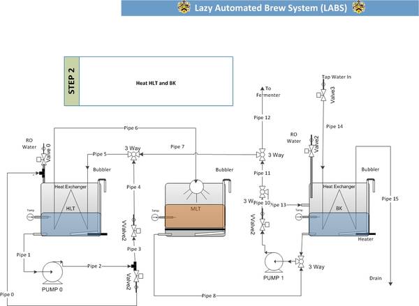
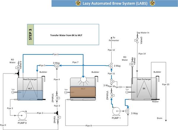
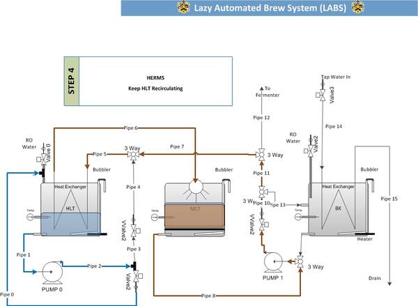
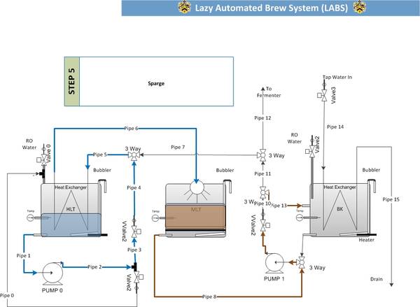
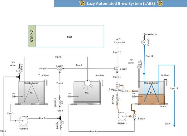
I learned a bunch from my old system and am now redesigning it. What do you all think?

LABS1.jpg

LABS2.jpg

LABS3.jpg

LABS4.jpg

LABS5.jpg

LABS6.jpg

LABS7.jpg

LABS8.jpg
 
Very nice! Have you thought about using your HLT in a ditches arrangement to cool your wort during the pump to fermentation? I know where I live the summertime water temp is way too warm to get to pitch temps.

What is the "bubbler"? Some of my friends from Wisconsin would try to drink from that, thinking it was a water fountain that dispensed beer!
 
Im outside of philly and get really cold water. Im actually going to change the BK coil for a chiller plate so I could always dunk that in ice water if need be. I want to keep cleanup down. I also hate coils in my kettles. The BK one just gets so messy. The HLT will be fine since the outside is water only. The system is all uC controlled and the bubbler is used to measure the volume of water in the kettles. I should change the name of that! This is actually V2 of my original system.
 
This worked great. I needed to add 2 checkvalves and I removed the BK coil for a plate chiller. Much cleaner and very fast cool down.
1426-labs.jpg


My code is working great as well. I keep adding more automation to everything. I do like to do a 2 or 3 temperature infusion mash which I will program in next.
 
Before I brew I run water heated to 180 with iodine through the whole system then out of those pipes. Pipes is misleasding they are high temp silicone tubing. I also leave the output to the fermenter in the BK during the boil. And during the mash I will have water in the BK at a high temp with tubing and parts that I use during the brew cycle . Thats actually a length of tubing with a quick disconnect so I can hook it up to a filter bag so I can get the gunk out after the boil (and steeping if needed), it can also be hooked up to the plate chiller or to another length to go to the fermenter.

After my brew I run PBW @ 180 through the system and then wash with 180 degree water.
 
I use it mostly for measuring and when there is no grain in there. It was like $5-$10 to add it in. I also use it to shut my pumps off when the MLT is empty. The sensor works fine for that since there is a false bottom.

Im using a .netmf C# uC from Fez/GHI.
 
Could you expand upon or link to a description of how the bubbler works? Is it just an empty tube with a pressure sensor on the end?

Awesome looking stuff btw. I look forward to pictures!
 
Sorry I missed this question. Its the same as what the brewtroller folks use. Copper/SS tube going down into the kettle with a constant stream of air to compensate for heat. In between the air pump and the bubbler is a differential air pressure sensor (fancy sounding) which gives a reasonable accurate level. The bubbles and pumping adds some ripple but I find with hardware and software filtering it isnt too bad. +/- 2cups. Could be worse like getting out of my chair and looking at a sight glass. So far my batches have been great so I dont think this is an issue. Also ad the end you are going for FG anyway so you might be boiling longer or adding water to hit your #s and not really relying on the level of the boil.
 
OMG I havent brewed since 11/10. things are still working. Im going to add some new features but this is a great setup. I know i havent been the best posting pictures but life got in the way. Soon to come some awesome code changes and a few tweaks to the layout. For $15 I get gallons of awesome beer so excuse my tardiness.
 
For $15* I get gallons of awesome beer so excuse my tardiness.

(*excluding time and cost spent on building this thing):D


fixed^^
but seriously- this thing is pretty cool. if money was no object i would have done the exact same thing. need pics nao!
 
OMG I havent brewed since 11/10. things are still working. Im going to add some new features but this is a great setup. I know i havent been the best posting pictures but life got in the way. Soon to come some awesome code changes and a few tweaks to the layout. For $15 I get gallons of awesome beer so excuse my tardiness.

A couple questions:

Are you using solenoid valves, or motor operated ball valves?

How many batches have you done on the new system?
 
I had uses solenoid valves and hate them for anything that has wort go through it. I’m going to switch the last one out to ball valves. They are really slow but I can deal with that. I am devising a cheap way to somewhat accurately know where the swing is.

Pics soon! i am so lazy with that!
 
If you are building the app in C# then I might have some useful bits and pieces I have built for the automated system if you are interested. The useful parts might be a scrolling graph, dial gauge, PID loop code, and an alarm monitor with speech synthesized audible annunciation and system shutdown.
 
FWIW here is the code from one of the PID loops in use in the One Touch application

private static double pVWa; // process variable
private static double kPWa; // Proportional
private static double kIWa; // Integral
private static double kDWa; // Derivative
private static double kLWa; // Integral limit to control windup
private static double kGWa; // Integral gain factor for loops with small process variable value range
private static double kCWa; // Time constant for recalculation of PID loop
private static double setpointWa; // Loop setpoint
private static double pGainWa; // internal proportional gain varaible
private static double intGainWa; // internal integral gain variable
private static double difGainWa; // internal differential gain variable
private static double errorWa; // internal setpoint error variable
private static double preverrorWa = 0; // internal error value used for derivative
private static double errorSumWa = 0; // internal error value used for integral calc
private static double rampWa; // internal variable used for ramping output
private static double rampWadf; // internal ramping variable
private static int sRWa; // calculation cycle delay variable


if (l1 < 10)
{
l1++;
}
if (l1 == 1)
{
kPWa = 0;
kIWa = 0;
kDWa = 0;
kLWa = 0;
kGWa = 0;
kCWa = 0;
pGainWa = 0;
intGainWa = 0;
difGainWa = 0;
errorSumWa = 0;
pidOutWa = 0;
}
if (l1 == 2)
{ // set valve to minimum opening in preperation for use
DataObject.boilerFlowValve = ((int)(SettingsObject.boilerValveMinimum * 40.95));
// ramping variable set
rampWadf = SettingsObject.waterSetpoint - .13;
}
if (l1 == 3)
{

if (SettingsObject.waterSetpoint >= .4)
{
// passing stored optimized variables setup for high flow use
// variables set in PID Tune application and stored in MySQL table
// and accessed through SettingsObject variables
kPWa = SettingsObject.water_FlowH_P;
kIWa = SettingsObject.water_FlowH_I;
kDWa = SettingsObject.water_FlowH_D;
kLWa = SettingsObject.water_FlowH_L;
kGWa = SettingsObject.water_FlowH_G;
kCWa = SettingsObject.water_FlowH_C;
}
if (SettingsObject.waterSetpoint <= .3)
{
// passing stored optimized variables setup for low flow use
// variables set in PID Tune application and stored in MySQL table
// and accessed through SettingsObject variables
kPWa = SettingsObject.water_FlowL_P;
kIWa = SettingsObject.water_FlowL_I;
kDWa = SettingsObject.water_FlowL_D;
kLWa = SettingsObject.water_FlowL_L;
kGWa = SettingsObject.water_FlowL_G;
kCWa = SettingsObject.water_FlowL_C;
}
}
// this sets the internal setpoint variable for the loop
// kept outside presets so it can be adjusted on the fly
setpointWa = SettingsObject.waterSetpoint;

// this passes the process variable to the loop calculation
pVWa = DataObject.boilerFlow;

//this increments the scan cycle variable based on the value of kCWa passed to PID Loop
if (sRWa < (int)(kCWa * 10))
{
sRWa++;
}
else
{ // this is the calculation scan test
if (sRWa >= (int)(kCWa * 10))
{
scanWa = true;
}
}
if (scanWa == true)
{
// this is used in other loops for ramping output limit
rampWa = 1;

errorWa = (setpointWa - pVWa);
errorSumWa += ((errorWa * kGWa) * rampWa);
pGainWa = kPWa * errorWa;

if (errorSumWa > (kLWa))
{
errorSumWa = (kLWa);
}
if (errorSumWa < (-kLWa))
{
errorSumWa = (-kLWa);
}

intGainWa = kIWa * errorSumWa;
difGainWa = kDWa * (errorWa - preverrorWa);
preverrorWa = errorWa;
// this is where output value is set
pidOutWa = SettingsObject.boilerValveMinimum + (pGainWa + intGainWa + difGainWa);
scanWa = false;
sRWa = 0;
}
if (pidOutWa > SettingsObject.boilerValveMaximum)
{
//check step to make sure it is within limits, fix if not
pidOutWa = SettingsObject.boilerValveMaximum;
}
if (pidOutWa < SettingsObject.boilerValveMinimum)
{
//check step to make sure it is within limits, fix if not
pidOutWa = SettingsObject.boilerValveMinimum;
}
//set output from 0 - 4096 for Opto22 output , scale to output value needed
DataObject.boilerFlowValve = ((int)(pidOutWa * 40.95));
 
Back
Top